Honeywell MV876B1018 F76S User manual
- Category
- Flat panel accessories
- Type
- User manual
This manual is also suitable for

PRODUCT DATA
62- 3015- 4
® U.S. Registered Trademark
Copyright © 1999 Honeywell Inc. • All Rights Reserved
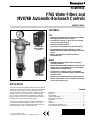
F76S Water Filters and
MV876B Automatic-Backwash Controls
APPLICATION
The F76S is a high flow capacity water filter used at point-of-
entry (POE) to remove sediment and debris from residential or
commercial water systems. Used as a prefilter, the F76S
protects elements of the water system, including specialized
treatment devices such as taste/odor or reverse osmosis
(R/O) or other common fixtures and appliances. The flow,
filtering capacity, and ease of cleaning make the F76S the
ideal filter for the most demanding applications.
The MV876 Automatic-Backwash Control is available as an
accessory. This control is fitted to the drain valve and is
programmed by the user to automatically perform the back-
wash function according to the desired interval.
FEATURES
F76
• Built-in backwash impeller provides efficient cleaning
with supply pressures as low as 22 psi.
• Increased flow capacity on 1/2 in. to 1-1/4 in. models
provides lower pressure drop.
• Robust backwash mechanism.
• No shut-off or disassembly is required for cleaning.
• During backwash, the F76S continues to supply
filtered water without interruption through a secondary
screen.
• Memory ring indicates when the next manual
backwash is due.
MV876
• MV876B1018 bayonet fitting simplifies upgrade to
automatic backwash.
• 16 field-selectable backwash intervals (from every four
minutes to once every three months) on the MV876B
eliminate need for external timer.
• Connections for external control on the MV876B
provide for use in automated systems and differential
pressure control.
• MV876B can be turned manually to initiate backwash.
• Battery (AA) backup to insure completion of backwash
cycle in spite of power loss.
F76S
MV876B1018
(Bayonet fitting
for F76S)
MV876B1000
(for F76A,G)
Contents
Application ........................................................................ 1
Features ........................................................................... 1
Specifications ................................................................... 2
Ordering Information ........................................................ 2
Planning the Installation ................................................... 4
Installation ........................................................................ 5
Wiring ............................................................................... 8
Operation .......................................................................... 8
F76S Replacement Parts List ........................................... 10
F76A,G Replacement Parts List ....................................... 12

F76S WATER FILTERS AND MV876B AUTOMATIC-BACKWASH CONTROLS
62-3015—4 2
ORDERING INFORMATION
When purchasing replacement and modernization products from your TRADELINE® wholesaler or distributor, refer to the
TRADELINE® Catalog or price sheets for complete ordering number.
If you have additional questions, need further information, or would like to comment on our products or services, please write or
phone:
1.
Your local Home and Building Control Sales Office (check white pages of your phone directory).
2.
Home and Building Control Customer Logistics
Honeywell Inc., 1885 Douglas Drive North
Minneapolis, Minnesota 55422-4386 (612) 951-1000
In Canada—Honeywell Limited/Honeywell Limitée, 155 Gordon Baker Road, North York, Ontario M2H 3N7.
International Sales and Service Offices in all principal cities of the world. Manufacturing in Australia, Canada, Finland, France,
Germany, Japan, Mexico, Netherlands, Spain, Taiwan, United Kingdom, U.S.A.
SPECIFICATIONS
F76S:
Models:
Water filters with 100 micron screens and hose connections.
F76S1007: 1/2 in. sweat and NPT threaded tailpieces.
F76S1015: 3/4 in. sweat and NPT threaded tailpieces.
F76S1023: 1 in. sweat and NPT threaded tailpieces.
F76S1031: 1-1/4 in. sweat and NPT threaded tailpieces.
F76S1049: 1-1/2 in. NPT threaded tailpieces.
F76S1056: 2 in. NPT threaded tailpieces.
Dimensions:
See Fig. 1.
Materials of Construction:
Body: Brass.
Screen: Stainless Steel.
Internal Construction: Acetal Copolymer.
Seals: NBR.
Ball Valve: Brass with PTFE Seals.
Sump: Engineered Plastic.
NOTE: Bronze sump available.
Inlet Pressure:
Minimum: 22 psi (with unrestricted backwash discharge).
Maximum:
Plastic Sump: 232 psi.
Bronze Sump: 400 psi.
NOTE: Pressures above 200 psi require an inlet pressure
gauge with a range wider than the standard.
Differential:
Maximum Recommended: 42 psi.
Operating Pressure Drop:
Maximum Recommended: 3 psi
(with clean screen).
Temperature (maximum):
Plastic Sump: 104°F (40°C).
Bronze Sump: 158°F (70°C).
Pipe Sizes (in in.):
1/2, 3/4, 1, 1-1/4, 1-1/2, and 2.
Connections:
Union on inlet and outlet: External NPT
threaded or sweat.
Capacity:
See Table 1.
Screen Sizes:
Shipped with Device: 100 microns.
Available Kits: 20, 50, and 200 microns.
NOTE: 20 microns = 900 mesh (approximate).
50 microns = 350 mesh (approximate).
100 microns = 175 mesh (approximate).
200 microns = 70 mesh (approximate).
MV876 Automatic-Backwash Controls:
Models:
MV876B1000: Valve with 24 Vac motor and timer replaces ball
valve drain port for automatic backwash at preprogrammed
intervals. 24V transformer not included. For use with
F76A,G Filters
only
.
MV876B1018: Bayonet mounted shaft of 24 Vac motor and
timer replaces ball valve manual control for automatic
backwash at preprogrammed intervals. 24V transformer
not included. For use with F76S Filters
only
.
Specifications:
Power: 4 VA.
Current: 170 mA.
Voltage: 24 Vac.
Cycle time: 20 seconds (approximate).
Timer: Variable. See Table 2.
Accessories (for F76S only except where noted):
0900747 Sump O Ring Kit (10 O rings) for 1/2 to 1-1/4 in. F76S.
0900748 Sump O Ring Kit (10 O rings) for 1-1/2 to 2 in. F76S.
0901444 Gasket Package (10 gaskets) for any 1/2 in. and
3/4 in. F76.
0901445 Gasket Package (10 gaskets) for any 1 in. F76.
0901446 Gasket Package (10 gaskets) for any 1-1/4 in. F76.
0901447 Gasket Package (10 gaskets) for any 1-1/2 in. F76.
0901448 Gasket Package (10 gaskets) for any 2 in. F76.
AF11S-1A Screen insert (100 microns) for 1/2 to 1-1/4 in. F76S.
AF11S-112A Screen insert (100 microns) for 1-1/2 to 2 in. F76S.
AF11S-1B Screen insert (20 microns) for 1/2 to 1-1/4 in. F76S.
AF11S-112B Screen insert (20 microns) for 1-1/2 to 2 in. F76S.
AF11S-1C Screen insert (50 microns) for 1/2 to 1-1/4 in. F76S.

F76S WATER FILTERS AND MV876B AUTOMATIC-BACKWASH CONTROLS
3 62-3015—4
Accessories (continued):
AF11S-112C Screen insert (50 microns) for 1-1/2 to 2 in. F76S.
AF11S-1D Screen insert (200 microns) for 1/2 to 1-1/4 in. F76S.
AF11S-112D Screen insert (200 microns) for 1-1/2 to 2 in. F76S.
KF11S-1A Clear Plastic Filter Sump Kit for 1/2 to 1-1/4 in. F76S.
KF11S-112A Clear Plastic Filter Sump Kit for 1-1/2 to 2 in. F76S.
FT09RS-1A Bronze Filter Sump Kit for 1/2 to 1-1/4 in. F76S.
FT09RS-112A Bronze Filter Sump Kit for 1-1/2 to 2 in. F76S.
KH11S-1A Ball Valve Assembly for 1/2 to 2 in. F76S.
M76K-200 Pressure Gauge, 200 psi maximum.
M76K-400 Pressure Gauge, 400 psi maximum.
U76S5007 Sweat Tailpiece for any 1/2 in. F76.
U76S5015 Sweat Tailpiece for any 3/4 in. F76.
U76S5023 Sweat Tailpiece for any 1 in. F76.
U76S5031 Sweat Tailpiece for any 1-1/4 in. F76.
U76S5039 Sweat Tailpiece for any 1-1/2 in. F76.
U76S5047 Sweat Tailpiece for any 2 in. F76.
U76T1004 Threaded Tailpiece for any 1/2 in. F76.
U76T1014 Threaded Tailpiece for any 3/4 in. F76.
U76T1022 Threaded Tailpiece for any 1 in. F76.
U76T1030 Threaded Tailpiece for any 1-1/4 in. F76.
U76T1038 Threaded Tailpiece for any 1-1/2 in. F76.
U76T1046 Threaded Tailpiece for any 2 in. F76.
ZR10K-1 Sump Wrench for any 1 in. or 1-1/4 in. F76.
ZR10K-112 Sump Wrench for any 1-1/2 in. or 2 in. F76.
ZR10K-12 Sump Wrench for 1/2 in. and 3/4 in. F76A,G.
ZR10K-34 Sump Wrench for 1/2 in. and 3/4 in. F76S.
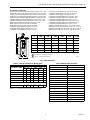
Fig. 1. F76S Dimensions.
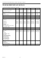
Table 1. Capacity in Gallons Per Minute (gpm).
NOTE: C
v
is equal to capacity at 1 psi pressure drop.
Table 2. MV876B Timer Selections.
1/2 INCH 6-11/16 (170) 4-5/16 (110) 3-13/16 (97) 17-11/16 (449) 13-13/16 (350) 6.4 (2.9)
3/4 INCH 7 (178) 4-5/16 (110) 3-13/16 (97) 17-11/16 (449) 13-13/16 (350) 6.4 (2.9)
1 INCH 8-1/4 (209) 5-1/8 (130) 3-13/16 (97) 17-7/8 (453) 13-13/16 (350) 6.8 (3.1)
1-1/4 INCH 8-3/4 (222) 5-1/8 (130) 3-13/16 (97) 17-7/8 (453) 13-13/16 (350) 7.3 (3.3)
1-1/2 INCH 9-11/16 (246) 5-15/16 (150) 4-3/4 (119) 20-15/16 (532) 16-7/16 (417) 8.8 (4.0)
2 IINCH 10-1/2 (267) 5-15/16 (150) 4-3/4 (119) 20-15/16 (532) 16-7/16 (417) 10.6 (4.8)
SIZE
L
l
DH h
1 DIMENSIONS IN INCHES AND (MILLIMETERS).
2 WEIGHT IN POUNDS AND (KILOGRAMS).
100
150
200
50
0
Honeywell
Braukmann
H
h
D
l
L
M18084
1
1 1 1 1
2
WEIGHT
Pressure Drop
(psi) Across Filter
Pipe Size (in.)
1/2 3/4 1 1-1/4 1-1/2 2
1 8 11 18 20 26 30
2 12162528 36 42
3 14193135 44 51
4 16223640 51 59
5 18254045 57 66
15 32 43 70 78 99 114
Flow Volume for 15 sec backwash at 60 psi inlet
— 3.2 3.2 4.0 4.0 4.7 4.7
Program Value Backwash Interval
1 4 minutes
2 8 minutes
3 16 minutes
4 32 minutes
5 1 hour
6 2 hours
7 4 hours
8 8 hours
9 17 hours
10 34 hours
11 3 days
12 6 days
13 11 days
14 23 days
15 45 days
16 3 months

F76S WATER FILTERS AND MV876B AUTOMATIC-BACKWASH CONTROLS
62-3015—44
PLANNING THE INSTALLATION
The F76S should be sized based on the required flow rate and
the resulting pressure drop across the filter. As a guideline for
most applications, the F76S should be sized to avoid pressure
drops exceeding 3 psi.
EXAMPLE:What size F76S is required to provide a flow
rate of 30 gpm? Reading across Table 1 at
3 psi pressure drop, a 1 in. filter can provide 31
gpm without exceeding 3 psi pressure drop.
An increased pressure drop across the filter results when
higher velocities are maintained to increase the capacity
through any given size filter. Severe pressure drops will be
encountered as capacity approaches that of the pipe size. To
ensure the backwash cycle operates properly and cleaning
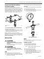
action is not reduced, follow all recommendations in Fig. 2.
Refer to Fig. 2a for an ideal installation.
NOTE: All filter installations are different. The size, type, and
amount of dirt and debris and the flow rate must
always be considered when choosing a screen and
deciding to install multiple F76 Water Filters in parallel.
Fig. 2. Installation recommendations.
100
150
50
0
200
Honeywell
Braukmann
M16488
Fig. 2a. Ideal F76S installation. A funnel
mounted directly under the backwash
port is the best installation layout.
Fig. 2b. Ensure the inlet pipe is not
downsized. Do not use 1/4 or 3/8 inch
tubing on 1/2 or 3/4 inch models.
Fig. 2c. Ensure the backwash outlet
pipe is not downsized, long, or
crimped. Instead, install a short
oversized pipe on the backwash outlet.
Do not use a low capacity solenoid
valve to automate the backwash cycle.
100
150
50
0
200
Honeywell
Braukmann
M16489
100
150
50
0
200
Honeywell
Braukma
nn
M16490
100
150
50
0
200
Honeywell
Braukmann
M16491
100
150
50
0
200
Honeywell
Braukmann
M16492
M16478
100
150
50
0
200
Honeywell
Braukmann
Fig. 2d. Ensure the backwash outlet is
not raised above the F76S. If the
backwash outlet must be raised above
the F76S, increase inlet pressure 5 psi
for every 10 feet that it is raised.
Fig. 2e. Ensure the F76S is not used
with an undersized pump. An
undersized pump may not provide
proper pressure or flow.
Fig. 2f. Ensure the F76S is not
installed in a bypass across a pump.

F76S WATER FILTERS AND MV876B AUTOMATIC-BACKWASH CONTROLS
5 62-3015—4
Commercial and Industrial Installations
(1-1/2 and 2 in. models)
Commercial and industrial installations have high flow
requirements. For proper operation, limit flow across the F76S
screen. For example, a two-inch pipe may have a 120 gpm flow
at 12 fps linear velocity across a clean screen. High linear
velocity impacts dirt deeply into the screen, making it difficult to
backwash and causing the screen to plug up quickly. In these
situations, install multiple F76 filters in parallel. See Fig. 3.
Fig. 3. Parallel installation of three F76S Water Filters.
Advantages of parallel installation:
• Increased cleaning capacity. Backwash interval is reduced.
• Elimination of system downtime. Can backwash one F76S
while the others maintain required flow.
Another consideration in commercial and industrial
installations is the backwash interval. Because of the high flow
requirements, screens need cleaning on a regular basis. An
MV876 Automatic-Backwash Control can be installed to back-
wash the F76S automatically.
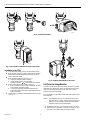
INSTALLATION
CAUTION
Equipment Damage Hazard.
Excessive pressure or temperature can damage
the device.
Ensure water temperature and pressure are below
maximum ratings specified.
CAUTION
Equipment Damage Hazard.
Excessive heating can damage internal parts.
Before sweating, separate the tailpieces and nuts from
the filter body.
F76S
When installing an F76S, use the following procedure:
1.
Shut off water supply by closing the water supply valve.
2.
Install the F76S in the water line with the arrow pointing
in the direction of water flow.
3.
Install pressure gauge in the F76S center port (see Fig. 4).
IMPORTANT
When using an MV876, stop here and install the MV876.
4.
Ensure the F76S air vent is open.
5.
Slowly open the water supply valve.
6.
Once the F76S sump fills with water, close the air vent
and fully open the water supply valve.
Fig. 4. Installing the F76S.
MV876
When adding an MV876 to an existing F76, the procedure can
vary depending on the F76 model.
Installation on an F76S
1.
Open the backwash outlet ball valve.
2.
Remove the backwash outlet handle.
3.
Install the MV876. See Fig. 5 and 6.
NOTE: When you rotate the MV876, it closes the
backwash outlet ball valve.
4.
Ensure the F76S air vent is open.
5.
Slowly open the water supply valve.
6.
Once the F76S sump fills with water, close the air vent
and fully open the water supply valve.
7.
Program the desired backwash interval by pushing the
program button until the desired interval number
appears in the display.
100
150
50
0
200
Honeywell
Braukmann
INLET
PIPE
M17360
100
150
50
0
200
Honeywell
Braukmann
ISOLATION VALVE.
1
1
1
1
1
100
150
50
0
200
Honeywell
Braukmann
100
150
50
0
200
Honeywell
Braukmann
M16480

F76S WATER FILTERS AND MV876B AUTOMATIC-BACKWASH CONTROLS
62-3015—46
Fig. 5. Installing the MV876.
Fig. 6. Final position of MV876 and F76S components.
Installation on an F76A
1.
Close the water supply valve to shut off water supply.
2.
Drain all water from the F76A by opening both a fixture
downstream, and the backwash outlet; loosen the air
vent on top of the F76A.
3.
Remove the backwash outlet (see Fig. 7):
a. Grip the F76A fixture with a wrench.
b. Using another wrench, turn the outlet
counterclockwise (viewed from the bottom).
4.
Connect the MV876 to the F76A (see Fig. 7):
a. Ensure a plastic washer is placed between the filter
sump and the backwash outlet.
b. Connect the externally threaded portion of the
MV876 backwash outlet to the internally threaded
F76A connection.
5.
Connect the hose fitting to the MV876 backwash outlet
(see Fig. 7).
Fig. 7. Installing the MV876B on the F76A.
Set Pressure Gauge Needles
The black needle on the pressure gauge measures the F76S
outlet pressure. When the F76S is running with clean screens,
there is a small pressure drop across the F76S (3 psi at
maximum recommended flow).
The red needle is a stationary needle that helps monitor back-
wash interval.
NOTE: The following assumes a constant inlet pressure. If
inlet pressure is variable, another gauge on the inlet
piping, or the air vent will provide more information
regarding actual pressure differential.
1.
Backwash F76S once to ensure the screens are clean.
2.
With the F76S in operation, rotate the clear gauge cover
to set the red needle to match the black needle.
M16481
MV876B
M16483
MV876B
M17357

F76S WATER FILTERS AND MV876B AUTOMATIC-BACKWASH CONTROLS
7 62-3015—4
As the F76S operates, screens become plugged. Backwash
the F76S when the black needle measures about five psi
lower than the red needle. However, each installation is
different. Residential applications can require backwash only
once a week, or once every few weeks. Industrial applications
can require backwash several times a day. To determine the
backwash interval, see Determining Backwash Interval in the
Operation section.
NOTE: For residential applications, backwash the F76S
once a week regardless of need is an excellent
guideline to follow to ensure F76S peak operating
efficiency.
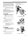
Fitting Batteries and Fuses
The batteries (not included) provide power to the MV876 in
the event of a power loss. This is desirable especially when
power loss occurs during the reverse rinsing cycle. To provide
this, the MV876 requires four AA alkaline batteries. Install
these batteries in the cover of the MV876:
CAUTION
Electrical Shock or Equipment Damage Hazard.
Can shock individuals or short equipment
circuitry.
Disconnect power supply before installation.
1.
Unscrew the four housing screws and set them aside.
(see Fig. 8).
IMPORTANT
Ensure that the connecting cable is protected from
damage while the MV876 cover is loose.
2.
Remove the MV876 cover (see Fig. 8).
3.
Insert four AA alkaline batteries (see Fig. 9).
4.
Replace the cover.
5.
Replace and tighten the four housing screws.
NOTES:
1. To avoid unnecessary battery drainage, connect
the MV876 to power as soon as possible after
inserting new batteries.
2. To ensure the availability of battery power, replace
the batteries after a power loss.
If the 800 mA fuse blows, replace it:
CAUTION
Electrical Shock or Equipment Damage Hazard.
Can shock individuals or short equipment circuitry.
Disconnect power supply before installation.
1.
Unscrew the four housing screws and set them aside.
(see Fig. 8).
IMPORTANT
Ensure that the connecting cable is protected from
damage while the MV876 cover is loose.
2.
Remove the MV876 cover (see Fig. 8).
3.
Remove and discard the old fuse (see Fig. 10).
4.
Insert a new 800 mA fuse (see Fig. 10).
5.
Replace the cover.
6.
Replace and tighten the four housing screws.
7.
Reconnect the power supply.
Fig. 8. Removing the MV876 cover.
Fig. 9. Installing batteries in the MV876.
Fig. 10. Replacing the MV876 fuse.
MV876B
M17352
M17353
MV876B
M17351

F76S WATER FILTERS AND MV876B AUTOMATIC-BACKWASH CONTROLS
62-3015—48
WIRING
CAUTION
Electrical Shock or Equipment Damage Hazard.
Can shock individuals or short equipment circuitry.
Disconnect power supply before installation.
IMPORTANT
All wiring must comply with applicable codes and
ordinances.
MV876
1.
Mount the AT140A1034 Transformer and wire as shown
in Fig. 11.
2.
Ensure the F76 air vent is open.
3.
Slowly open the water supply valve.
4.
Once the F76 sump fills with water, close the air vent
and fully open the supply valve.
5.
Reconnect power to the system. When the system is
powered, the MV876 will run through one backwash
cycle (approximately 20 seconds).
6.
Set MV876 backwash interval to the desired setting.
See the Operation section.
7.
Check MV876 operation by interrupting primary power
to the transformer. When power is switched back on, the
MV876 will backwash the F76 once.
Fig. 11. Wiring diagram for F76 with MV876.
OPERATION
The F76S Water Filter removes sediment and debris from the
water using an upper and lower screen. During normal
operation, no water passes through the upper screen. Water
is filtered as it flows through the lower screen. (See Fig. 12a.)
With continued operation, the lower screen becomes
obstructed, reducing efficiency and creating a pressure drop
across the F76S. Backwash the F76S periodically. Suggested
interval is either once per week (residential applications) or
when the black needle measures about five psi lower than the
red needle.
To backwash the F76S manually, open the backwash outlet
on the F76S bottom. This forces the entire filter insert down-
wards. Water flow to the lower screen outer side is blocked.
The upper filter removes sediment and debris from the water.
While the upper screen filters the water. Some of the water
passing through the upper screen is directed through the
impeller to backwash the lower screen (from inside to out-
side). Remaining filtered water meets the needs downstream.
Water jets from the rapidly spinning impeller enhance the
reversed water flow. The reverse flow removes trapped
sediment and debris from the lower filter. This sediment drains
out the backwash outlet. Cleaning the lower screen requires
approximately 20 seconds. See Fig. 12b.
The F76S requires no maintenance if backwashed at the
proper interval.
Determining Backwash Interval
All F76S applications are different and require backwashing at
different intervals. Backwash interval is directly proportional to:
— The level and type of sediment in the local water supply.
— Water usage.
EXAMPLE:In northern states, water usage is higher in
summer months than in winter months due to
lawn watering in the summer. Therefore, the
F76S should be backwashed more often in
summer months than in winter months.
By accurately determining a proper backwash interval, the
F76S will operate at a higher efficiency.
To determine the F76S backwash interval:
1.
Backwash the system once to ensure the lower screen
is clean.
2.
The black pressure gauge needle measures outlet pressure.
With clean screens, inlet pressure equals outlet pressure
because of negligible pressure drop across the F76S.
3.
Rotate the clear gauge cover to set the red needle to
match the black needle.
4.
Record the date and time.
5.
Monitor the F76S closely. Over time, the screens
become obstructed and outlet pressure drops.
NOTE: The F76S requires a backwash when the black
needle measures about five psi lower than the
red needle. Installations do vary and can
require a backwash at different times.
6.
Record date and time again. Residential applications
can require an F76S backwash only once every few
weeks to once per week. Industrial applications can
require an F76S backwash several times a day.
7.
Backwash the F76S regularly at the determined interval.
A backwash can be done manually or automatically.
a. Manual Backwash: Open the backwash outlet for
approximately 30 seconds.
NOTE: The amount of time required varies among
installations. However, 30 seconds is the
standard guideline to clean the lower screen.
b. Automatic Backwash: Install an MV876 Automatic-
Backwash Valve and select the backwash interval.
See the Operation section.
L1
(HOT)
L2
1
POWER SUPPLY. PROVIDE DISCONNECT MEANS AND OVERLOAD
PROTECTION AS REQUIRED.
1
M16484
MV876

F76S WATER FILTERS AND MV876B AUTOMATIC-BACKWASH CONTROLS
9 62-3015—4
Fig. 12. Water flow through the F76S.
SCREEN
BACKWASH
IMPELLER
a. F76S DURING NORMAL FLOW b. F76S DURING BACKWASH CYCLE
DEBRIS AND
SEDIMENT
M17362
ENLARGED
CROSS SECTION
ENLARGED
CROSS SECTION

F76S WATER FILTERS AND MV876B AUTOMATIC-BACKWASH CONTROLS
62-3015—410
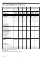
F76S REPLACEMENT PARTS LIST (SEE FIG. 13)
PARTS AND ACCESSORIES FOR NEW STYLE F76S FILTERS:
N/A = Part number not available at time of printing.
a
Sold in packs of ten.
Description 1/2 inch 3/4 inch 1 inch 1-1/4 inch 1-1/2 inch 2 inch
(A) Pressure Gauge (new style F76S only)
Standard Pressure (230 psi) M76K-200 M76K-200 M76K-200 M76K-200 M76K-200 M76K-200
High Pressure (400 psi) M76K-400 M76K-400 M76K-400 M76K-400 M76K-400 M76K-400
(B) Tailpieces (same for new and old style)
Sweat U76S5007 U76S5015 U76S5023 U76S5031 U76S5039 U76S5047
Threaded (shown) U76T1004 U76T1014 U76T1022 U76T1030 U76T1038 U76T1046
(C) Union Nuts N/A N/A N/A N/A N/A N/A
(D) Tailpiece Gaskets (sold in packs of 10) 0901444 0901444 0901445 0901446 0901447 0901448
(E) Guide Barrel N/A N/A N/A N/A N/A N/A
Screen Insert Complete (new style only)
20 Micron AF11S-1B AF11S-1B AF11S-1B AF11S-1B AF11S-112B AF11S-112B
50 Micron AF11S-1C AF11S-1C AF11S-1C AF11S-1C AF11S-112C AF11S-112C
100 Micron AF11S-1A AF11S-1A AF11S-1A AF11S-1A AF11S-112A AF11S-112A
200 Micron AF11S-1D AF11S-1D AF11S-1D AF11S-1D AF11S-112D AF11S-112D
Includes:
(F) Barrel O Ring
(G) Impeller and Screen Assembly
(J) Chamber O Ring
(H) Base Spring N/A N/A N/A N/A N/A N/A
(J) Chamber O Ring (sold in packs of 10) 0900747 0900747 0900747 0900747 0900748 0900748
Filter Sump Kits (new style only)
Clear Plastic KF11S-1A KF11S-1A KF11S-1A KF11S-1A KF11S-112A KF11S-112A
Bronze FT09RS-1A FT09RS-1A FT09RS-1A FT09RS-1A FT09RS-112A FT09RS-112A
Includes:
(J) Chamber O-Ring
(K) Sump
(L) Ball Valve O-Ring
(M) Integrated Ball Valve
(N) Memory Ring
(P) Ball Valve Bowl
(Q) Ball Valve Knob
(R) Joint Ring Seal
(S) Drain Connector
Ball Valve Assembly (new style only)
Includes:
(M) Ball Valve
(L) Ball Valve O-Ring
KH11S-1A KH11S-1A KH11S-1A KH11S-1A KH11S-1A KH11S-1A
Sump Wrench ZR10K-34 ZR10K-34 ZR10K-1 ZR10K-1 ZR10K-112 ZR10K-112

F76S WATER FILTERS AND MV876B AUTOMATIC-BACKWASH CONTROLS
11 62-3015—4
Fig. 13. F76S exploded view. Parts are keyed to F76S Replacement Parts List.
100
150
50
0
200
Honeywell
Braukmann
A
C
E
B
D
C
B
D
F
G
Q
K
L
M
H
J
S
R
P
N
T
M18073
OR

F76S WATER FILTERS AND MV876B AUTOMATIC-BACKWASH CONTROLS
62-3015—412
F76A,G REPLACEMENT PARTS LIST (SEE FIG. 14)
N/A = Part number not available at time of printing.
a
Sold in packs of ten.
b
PF76C1023 does not include drain tap and red handle and screw.
Description 1/2 inch 3/4 inch 1 inch 1-1/4 inch 1-1/2 inch 2 inch
(A) Pressure Gauge
F76A & F76B 0901537 0901537 0901537 0901537 0901537 0901537
F76G & F76H 5267400 5267400 5267400 5267400 5267400 5267400
(B) Tailpieces (for new and old style)
Sweat U76S5007 U76S5015 U76S5023 U76S5031 U76S5039 U76S5047
Threaded (shown) U76T1004 U76T1014 U76T1022 U76T1030 U76T1038 U76T1046
(C) Union Nuts N/A N/A N/A N/A N/A N/A
(D) Tailpiece Gaskets
a
0901444 0901444 0901445 0901446 0901447 0901448
(E) Ring (plastic) N/A N/A N/A N/A N/A N/A
Screen Kit
20 Micron QF76Q2007 QF76Q2007 QF76Q2015 QF76Q2015 QF76Q2023 QF76Q2023
50 Micron QF76R2030 QF76R2030 QF76R2038 QF76R2038 QF76R2046 QF76R2046
100 Micron QF76S2051 QF76S2051 QF76S2059 QF76S2059 QF76S2067 QF76S2067
200 Micron QF76T2074 QF76T2074 QF76T2082 QF76T2082 QF76T2090 QF76T2090
Includes:
(F) Upper Screen
(H) Barrel O Ring
(L) Lower Screen
Internal Seal Kit
Includes: (H) Barrel O Ring
(K) Screen Seal
(Q) Chamber O Ring
(S) Joint Ring Seal
N/A N/A N/A N/A N/A N/A
Filter Insert Kit
(F) Upper Screen
(G) Upper Guide Barrel
(H) Barrel O Ring
(J) Lower Guide Barrel
(K) Screen Seal
(L) Lower Screen
(M) Impeller
(N) Lower Screen Support
(P) Conical Base Spring
(Q) Chamber O Ring
QF76G2053 QF76G2053 QF76G2061 QF76G2061 QF76G2069 QF76G2069
Filter Sump Kits
Clear Plastic PF76C1007 PF76C1007 PF76C1015 PF76C1015
PF76C1023
b
PF76C1023
b
Bronze 202913 202913 202914 202914 202915 202915
Includes:
(Q) Chamber O-Ring
(R) Sump
(S) Joint Ring Seal
(T) Drain Tap (Backwash Outlet)
b
(U) Red Handle and Screw
b
(U) Red Handle and Screw 251550 251550 251550 251550 251550 251550
Sump Wrench ZR10K-12 ZR10K-12 ZR10K-1 ZR10K-1 ZR10K-112 ZR10K-112

F76S WATER FILTERS AND MV876B AUTOMATIC-BACKWASH CONTROLS
13 62-3015—4
Fig. 14. F76A,G exploded view. Parts are keyed to F76A,G Replacement Parts List.
100
150
50
0
200
Honeywell
Braukmann
A
C
E
T
B
D
C
B
D
F
G
H
J
K
L
M
N
P
Q
R
S
U
M746

62-3015—414

15 62-3015—4

www.honeywell.com
62-3015—4 B.B. Rev. 10-99 www.honeywell.ca/braukmann/
Home and Building Control Home and Building Control
Honeywell Inc. Honeywell Limited-Honeywell Limitée
Honeywell Plaza 155 Gordon Baker Road
P.O. Box 524 North York, Ontario
Minneapolis, MN 55408-0524 M2H 3N7
Printed in U.S.A. on recycled
paper containing at least 10%
post-consumer paper fibers.
-
 1
1
-
 2
2
-
 3
3
-
 4
4
-
 5
5
-
 6
6
-
 7
7
-
 8
8
-
 9
9
-
 10
10
-
 11
11
-
 12
12
-
 13
13
-
 14
14
-
 15
15
-
 16
16


Honeywell MV876B1018 F76S User manual
- Category
- Flat panel accessories
- Type
- User manual
- This manual is also suitable for
Ask a question and I''ll find the answer in the document
Finding information in a document is now easier with AI
Related papers
-
Honeywell C6097A User manual
-
-
-
-
Honeywell D15P Owner's manual
-
Honeywell RV277 Owner's manual
-
-
-
Honeywell T410B1004 Installation guide
-
Other documents
-
Antunes 9700913 Installation Instructions Manual
-
 Tekleen LPF4LP User manual
-
Rittal Perforex LC 3015 Owner's manual
-
Grunbeck GENO® backwash filter MXA Operating instructions
-
Moen 930-003 NPT, 930-004 Solder Smart Water Network Installation guide
-
 Baker Hydro HRF Series Owner's manual
-
US Water Green Wave Fusion User manual
-
Hydrotech 89BM-150 Operating instructions
-
 US Water Systems 385-GWU-1500 Owner's manual
-


