© 2020 OJ Electronics A/S
Outdoor sensor ETF, fig. 2 + 4:
For use in conjunction with gutter sensor ETOR.
Can also be used separately for the detection
of temperature alone. The sensor should be
mounted on the wall under the eaves on the
north side of the building.
Sensor cables
ETOG and ETOR are supplied with 10 m cable,
which can be extended up to approx. 200 m
using standard installation cable: 6x1.5 mm²
for ETOG and 4x1.5 mm² for ETOR. The ETF
cable can be up to approx. 50 m in length.
Sensor cables must be installed in accordance
with current regulations. They must never be
installed parallel to power cables as electrical
interference may distort the sensor signal.
Thermostat installation
The thermostat should be DIN-rail mounted in
an approved panel.
Connect supply voltage to terminals 1 and 2.
Electrical installation must be performed in
accordance with applicable local regulations.
Setup
ETR2 can be set up for ice and snow melting
on outdoor areas in conjunction with ETOG
sensors or in gutters/downpipes in conjunction
with ETOR and ETF sensors.
• Electric heating control with ETOG
(fig. 5 + 7):
Connect 1 ETOG sensor to terminals 8-14.
Connect heating cable to output relay
according to fig. 7.
• Electric heating control with ETOR + ETF
(fig. 6 + 7):
Connect 1 ETOR sensor to terminals 10-14.
Note that the pink and grey wires must not be
connected.
Connect 1 ETF sensor to terminals 8 and 9.
Connect heating cable to output relay
according to fig. 7.
How to program the sensitivity:
1. Turn off the power to the ETR2.
2. Connect a wire between terminals 8 and 9
3. Connect a wire between terminals 10 and 11
4. Turn the TIME SET knob to max. (constantly
on).
5. Turn the TEMP SET knob to max. (10).
6. Turn on the power. The LED for ON will flash.
a. The LEDs for TEMP, MOIST and RELAY
will light constantly, indicating the factory
setting for sensitivity level.
7. Program the sensitivity level by turning the
TIME SET knob from 1-5 (1=min., 2=low,
3=normal/factory setting, 4=high, 5=max.).
a. The combination of LEDs will indicate the
programmed sensitivity (see matrix below).
8. Turn off the power and select the required
settings for temperature (TEMP SET) and
after-run time (TIME SET).
9. Remove the wires connecting terminals 8 and
9 and terminals 10 and 11.
10.
Install the temperature sensor and moisture
sensor as normal.
57653F 06/20 (BCH)
TECHNICAL DATA
Thermostat ETR2-1550:
Supply voltage ..........230 V AC ±10 %, 50-60 Hz
Output relay (NO) ..........................................16 A
On/off differential .......................................0.3 °C
Temperature Setting for Startup ............0/+10 °C
Run-on time ..........................................0-5 hours
Ambient temperature ......................... -10/+50 °C
Ambient air humidity .............................10-95 %
Enclosure rating ...........................IP 20 / Nema 1
Power consumption .....................................3 VA
Weight ...................................................... 200 g
Dimensions H/W/D 86/52/59 mm
Ground sensor type ETOG-55:
Designed to be embedded in outdoor areas.
Detection ....................Moisture and temperature
Mounting ........................................Outdoor area
Enclosure rating ...........................................IP 68
Ambient temperature ......................... -50/+70 °C
Dimensions ....................................H32, Ø60 mm
Embedded ground sensor - ETOG-56/ETOK-1:
Designed to be embedded in outdoor surfaces.
Detection....................Moisture and temperature
Mounting...................................Outdoor surface
Housing.......................................................IP 68
Ambient temperature......................... -50/+70 °C
Dimensions, sensor H/Ø)....................32/60 mm
Dimensions, tube (H/Ø) ...................78/63.5 mm
Gutter sensor type ETOR-55:
Designed to be mounted in gutter or downpipe.
Is used together with outdoor sensor type ETF.
Detection ...............................................Moisture
Mounting ..............................Gutter or downpipe
Enclosure rating ...........................................IP 68
Ambient temperature ......................... -50/+70 °C
Dimensions H/W/D .......................105/30/13 mm
Outdoor sensor type ETF-744/99:
Detection .........................................Temperature
Mounting ...................................................... Wall
Ambient temperature ......................... -50/+70 °C
Dimensions H/W/D .........................86/45/35 mm
NOTE: The snow and ice melting system
is deactivated in the event of sensor
failure - regardless of sensor type.
SENSOR INSTALLATION
Ground sensor ETOG, fig. 1 + 3:
For installation in outdoor surfaces where ice and
snow are a regular problem. The sensor must be
embedded horizontally with its top flush with the
surrounding surface.
The sensor cable must be installed in accordance
with current regulations.
NOTE: We strongly recommend the use of cable
pipes in order to protect the sensor cable. Detailed
installation instructions are supplied with the
sensor.
With ETOG-55, use the accompanying installation
plate.
With ETOG-56, use the ETOK-1 mounting kit.
NOTE: Remove the installation plate from
ETOG-55 before first start-up.
Gutter sensor ETOR, fig. 2 + 4:
For installation in a gutter or downpipe on the
sunny side of the building. It is important to
ensure that the sensor contact elements face
against the flow of melt water. Be aware that
the pink and grey wire must not be installed.
Detailed installation instructions are supplied
with the sensor.
English
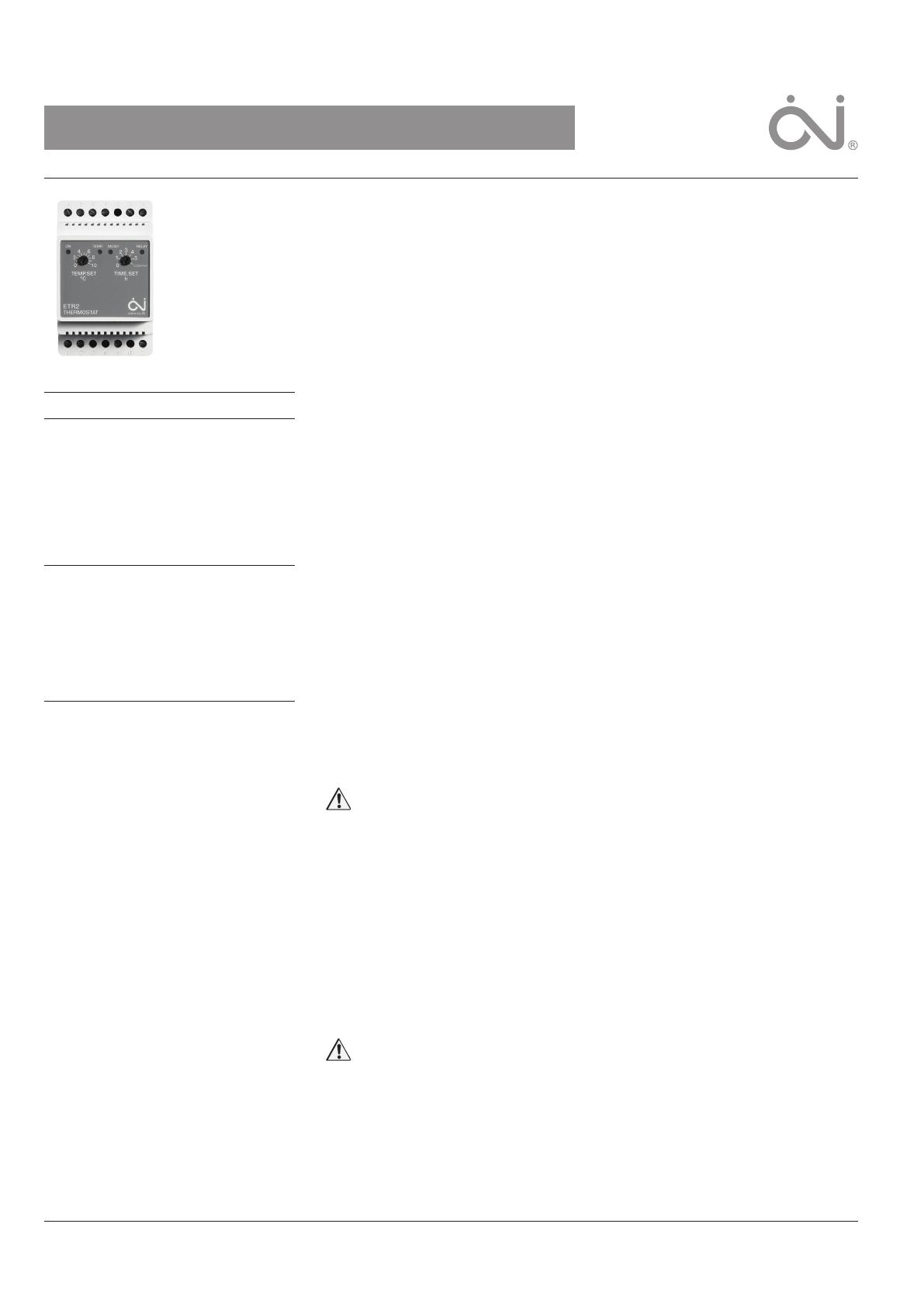
Type ETR2 is an electronic thermostat for
economical ice and snow melting on outdoor
areas and in gutters. Ice forms due to a
combination of low temperature and moisture.
ETR2 detects temperature and moisture and
the snow melting system will usually only be
activated if snow or ice is present. ETR2 is
suitable for controlling electric heating cables.
Product program
ETR2-1550 Thermostat.
ETOG-55 Ground sensor for detecting
temperature and moisture.
ETOR-55 Gutter sensor for detecting moisture.
ETOG-56/
ETOK-1 Embedded ground sensor for
detecting temperature and moisture.
ETF-744/99 Outdoor sensor for detecting
temperature.
CE MARKING
OJ Electronics A/S hereby declares that
the product is manufactured in accordance
with Council Directive 89/336/EEC on
electromagnetic compatibility (and subsequent
amendments) and Council Directive 2006/95/
EEC on electrical equipment designed for use
within certain voltage limits.
Applied standards
EN 61000-6-3, EN 61000-6-2, EN 60730-1 and
EN 60730-2-9.
The product may only be used if the complete
installation complies with current directives.
The product carries a manufacturer’s warranty if
installed in accordance with these instructions
and current regulations.
If the product has been damaged in any way,
e.g. during transport, it must be inspected and
checked by authorised personnel before being
connected to the power supply.
WARNING – Important safety instructions.
Always disconnect the power supply before
performing installation or maintenance work on
this control unit or any of the components con-
nected to it. This control unit and the compo-
nents connected to it should only be installed
by qualified electricians. Electrical installation
must be performed in accordance with applica-
ble local regulations.
INSTRUCTIONS
OJ Microline
®
Type ETR2
• English
• Deutsch
• Français
• Русский
• Polski
• Italiano
• Česky


