Installation Requirements
Water Supp!y,R#quirements
• All installations must meet local plumbing code requirements.
• The water shutoff should be located in the base cabinet on
either side of the refrigerator or some other easily accessible
area. The right-hand side is recommended.
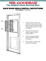
NOTE: If the water shut off valve is in the back walt behind the
refrigerator, it must be at an angle so that the water line is not
kinked when the refrigerator is pushed into its final position.
\
Possible water
line locations
t
1 "
(2.5 cm)
(15.2 cm) (15.2 cm)
• If the water shutoff valve is not in the cabinets, the plumbing
for the water line can come through the floor. A ½" (1.3 cm)
hole for plumbing should be drilled at least 6" (15.2 cm) from
the right or left hand side cabinet or panel. On the floor, the
hole should be no more than 1" (2.5 cm) away from the back
wall. See Connect Water Supply.
• Your refrigerator dealer has a kit available with a ¼" (6.4 mm)
saddle-type shutoff valve. Before purchasing, make sure a
saddle-type valve complies with your local plumbing codes.
• Do not use a piercing-type or 3/16"(4.8 mm) saddle valve which
reduces water flow and clogs more easily.
• Install the water supply line only in areas where the household
temperatures will remain above freezing.
Water Pressure
A cold water supply with water pressure between 30 and 120 psi
(207 and 827 kPa) is required to operate the water dispenser and
ice maker. If you have questions about your water pressure, call a
licensed, qualified plumber.
Reverse Osmosis Water Supply
IMPORTANT: The pressure of the water supply coming out of
a reverse osmosis system going to the water inlet valve of the
refrigerator needs to be between 30 and 120 psi (207 and 827
kPa). If a reverse osmosis water filtration system is connected
to your cold water supply, the water pressure to the reverse
osmosis system needs to be a minimum of 40 to 60 psi (276 to
414 kPa).
If the water pressure to the reverse osmosis system is less than
40 to 60 psi (276 to 414 kPa):
• Check to see whether the sediment filter in the reverse
osmosis system is blocked. Replace the filter if necessary.
• Allow the storage tank on the reverse osmosis system to refill
after heavy usage.
• If your refrigerator has a water filter cartridge, it may further
reduce the water pressure when used in conjunction with a
reverse osmosis system. Remove the water filter cartridge.
If you have questions about your water pressure, call a licensed,
qualified plumber.
Radius
Be sure there is adequate ceiling height to stand the refrigerator
upright when it is moved into place.
• The dolly wheel height must be added to the tipping radius
when a dolly is used.
• If needed, the tipping radius can be reduced. See Reduce
Tipping Radius.
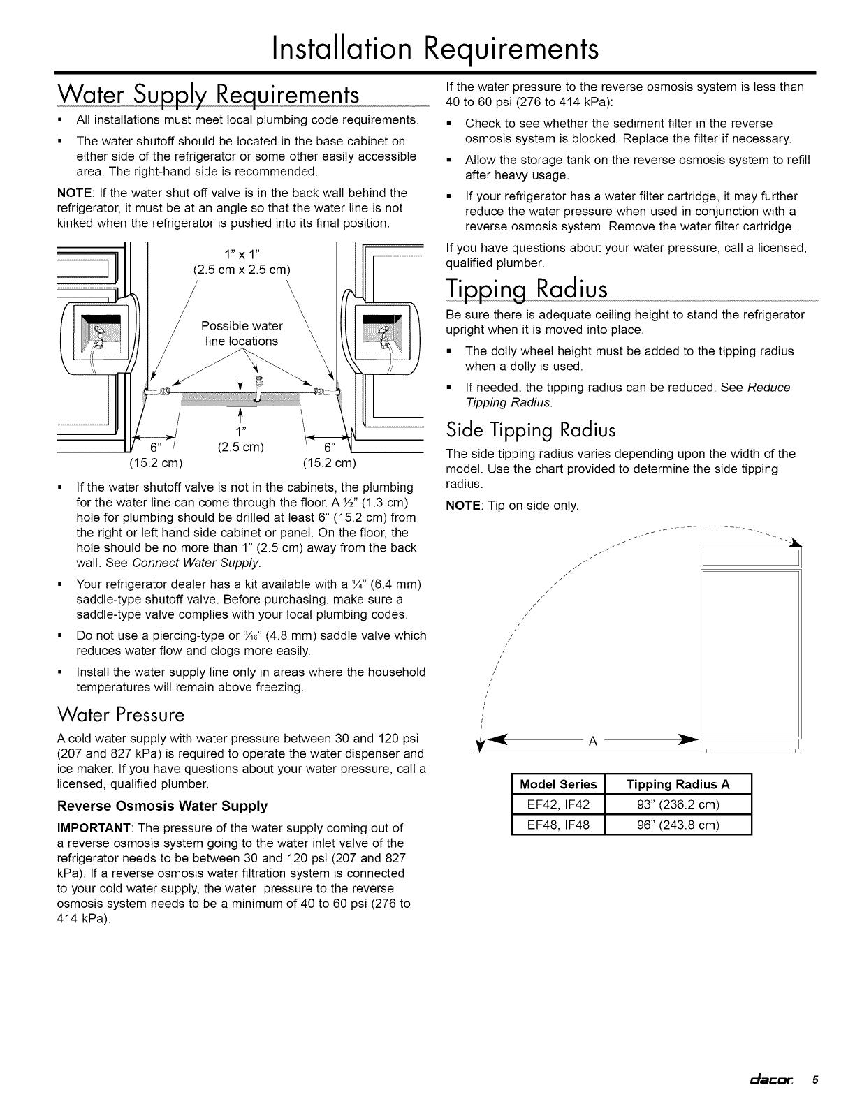
Side Tipping Radius
The side tipping radius varies depending upon the width of the
model. Use the chart provided to determine the side tipping
radius.
NOTE: Tip on side only.
//
//////_///// _
ii ii
Model Series Tipping Radius A
EF42, IF42 93" (236.2 cm)
EF48, IF48 96" (243.8 cm)
_:_acar 5