Page is loading ...

PRO-GRIND
SHARPENING SYSTEM
Version 1.0
Turn o Power Ear Protection
Sharp
CAUTION
Eye Protection
Respiratory
Protection
Disconnect
tool from
power source
before per-
forming any
adjustments.
Always wear
proper eye
protection
when working
with machinery
and tools.
Always wear
proper ear
protection when
working with
machinery.
Always wear
proper respiratory
protection when
working near
airborne dust
particles.
Use caution when
handling sharp objects
(saw blades, router
bits, turning tools and
so on). Use protective
gloves whenever
possible.
Please read and fully understand
any and all safety materials that
came with your power tools or
machinery before operation. Always
follow all safety guidelines set in
place by the power tool or machine
manufacturer.
Safety First

J
K
1
1
1
1
2
2
2
1
3
1
Locking Knob Female
Milled Platform Arm
Solid Platform Arm
A
B
C
D
E
F
G
H
I
Long PVC Bushing-BK
No.
Part Description Qty
1
1
2
AA
BB
CC
M6 x 100mm Bolt
Tool Rest Mount
Tool Rest
3/16" x 1-1/4" Bolt
Knurled Knob
Tool Holder Top
Tool Holder Bottom
Platform
L
1
4
1/4" x 3/8" Screw-BK
M6 x 90mm Bolt
No.
Part Description
Qty
1
#10 x 5/8" Wood Screw
1
1
4
Base
Quad Angle Setting Gauge
Magnetic Micro Bevel Block
2 Sided Setup Block #1
Setup Block Post
2 Sided Setup Block #2
1
1
2
1
1
1
V
M
N
O
P
Q
R
S
T
U
PVC Bushing BK
Platform Arm Attachment
Platform Base
Locking Knob Male
No.
Part Description
Qty
No.
Part Description
Qty
1
Locking Knob Female
4
1
1
Multi-Grind Mounting Bar
1
EE
FF
GG
HH
II
Glide Setup Blocks
4
JJ
Multi-Grind Jig
#10 x 5/8" Wood Screw
Base
A B C D E F G H I
J
R S T U
V
GG
II
FF
EE
AA BB CC
HH
K L M N O P QI
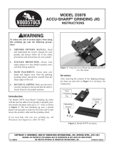
Platform & Accessories Exploded View Multi-Grind & Accessories Exploded View
Please Note:
Some parts in the Multi-Grind view are
identical to parts in the Platform view. We
have separated these parts for easier
identication.
Please Note:
See last page for instructions on how to use the Yellow
Glide Blocks (JJ) before mouting the jig to wooden base
JJ
Part Identication
Grinder Preparation
Lay out the parts and pieces to your new Pro-Grind sharpening system on a clean work surface. Review the drawings below and
make sure you have all the parts and pieces as shown below before beginning with the setup process. Some basic assembly of the
parts and accessories may be required before setting up the ProGrind System.
For optimal performance, we recommend that your grinder and the Pro-Grind sharpening system be mounted on the same surface.
Typically this is done by securing the grinder to a 3/4” piece of plywood that is slightly larger than the grinder. This ensures that the
Pro-Grind system and the grinder will always be aligned.
21
Make a straight line
mark directly under
the center of the
grinding wheel as
shown in this image.
Repeat this process
for the other side of
the grinder.
Secure the grinder to a piece of plywood. Leave room on the front side for
the Pro-Grind system and square it to the plywood. In this example we used
a 3/8” bolt with a t-nut, washer and lock washer on each side of the grinder.
Please Note that it may be necessary to add a "riser" block to gain
clearance for your grinder wheels as shown in gure 1a.
1a

Attach & Secure Pro-Grind Bases
General Use
When attaching and securing the two Pro-Grind bases (Q or EE) to the plywood base, be sure to keep the Pro-Grind bases running
parallel to the grinding wheels. This is achieved by lining up the Pro-Grind bases with the lines marked in step 1.
The Pro-Grind sharpening system allows you to perform three basic sharpening processes or
methods: The Platform, Multi-Grind and Tool Rest methods allow you to have the exibility
to sharpen many dierent types of turning tools without a whole lot of planning or
math. We have done the math and legwork for you to make your tool sharpening
process much easier.
1 2
Using the bottom corner of the base (Q or EE) as a
guide, align the base with the mark we made in step
1 with the provided screws (P & FF) secure the bases.
Note: to use the optional Glide Blocks for setup, please
see the last page in these instructions.
Repeat this process for the other side in the op-
posite direction. Once secured, double check the
alignment of the bases to the grinding wheels.
Base Bottom Corner
Platform
Multi-Grind Tool Rest
Ideal for skews and at
edge tools
Ideal for gouges and other
curved tools
Ideal spindle
roughing gouges

Platform Method
Using the platform gives you complete control over at edge turning tools like skews, parting tools and scrapers. Your tool ts
neatly into the tool holder and can then slide back and forth in through the platform slot. The Quad Angle Setting Gauge (included)
gives you the perfect angle settings for the four various tools that can be sharpened using this method.
2
1 1
2
Place your tool to be sharpened into the Tool Holder / Slot Guide. Square
the tool to the sliding assembly and secure the tool into the Tool Hold-
er with the brass knobs. Place your tool with the Tool Holder and Slot
Guide into the platform slot. Slightly loosen the brass knobs on the Tool
Holder and slide your tool up toward the grinding wheel until it touches
the wheel and secure the tool holder with the brass knobs. Make any
necessary adjustments to the platform and secure the platform. Turn the
grinder on and slide the tool side to side across the grinding wheel.
With the Quad Angle Setting Gauge, set the angle of the platform by
identifying your tool on the gauge. Place the gauge on the platform and
adjust the platform until the two points on the gauge touch the wheel.
Secure the platform and sharpen your tool using a side to side motion.
With the Quad Angle Setting Gauge, set the angle of the plat-
form by identifying your tool on the gauge. Place the gauge on
the platform and adjust the platform until the two points on the
gauge touch the wheel. Secure the platform.
Accessories Used for this Method
Platform Only
Platform with Tool Holder
Platform Assembly
Tool Holder /
Slot Guide
All are included
Quad Angle
Setting Gauge
Choose your tool to sharpen
Set the correct platform angle and sharpen
Use of the Tool Holder / Slot Guide
Set the correct platform angle
Skew
Scraper
Parting Tool

Multi-Grind Method
Accessories Used for this Method
The Multi-Grind method helps you achieve a sharp keen edge on rounded edge tools like gouges. The rolling motion along with the
ProGrind setup process gives you the ability to sharpen your gouges with ease and total accuracy without doing any math. We have
done all the "legwork" for you, now it's time to sharpen those tools.
Multi-Grind Jig
Multi-Grind Bar
All are included
2 Sided
Setup Block #1
2 Sided
Setup Block #2
Magnetic Micro Bevel
Setup Block
Side 1
Side 1
Side 2
Please note:
In this system there are two setup blocks. Each block has dierent
settings printed on both sides
Side 2
Fingernail Grind on Spindle Gouge
A spindle gouge (denoted by it’s much shallower ute)
with a ngernail grind enables a turner to turn beads and
coves with much steeper sides and more pronounced an-
gles between elements in spindle work. One must maintain
a rounded tip while pulling the wings back. This congura-
tion avoids catching the edge of the wings when rolling a
bead or scooping out a cove.
Standard Grind on Bowl Gouge
The standard grind is used by most tool manufacturers for
bowl gouges regardless of diameter of the tool. This is a
general use type of grind that is best used on dry wood for
both inside and outside of bowls, plates and platters. This
grind is easy to use for most skill levels.
Short Grind on Bowl Gouge
The short grind is a special type of grind that is useful for
nishing the bottom of bowls with tall sides, such as cala-
bash or semi-hollow forms. This type of grind is best used
with narrow openings which prevent using long grinds or
standard grinds on the very bottom of the inside. It is also
known as a "Bottom Feed Grind" by many in the woodturn-
ing world.
Long Grind on Bowl Gouge
This is generally the most useful all around bowl gouge
grind and is the preferred grind for green wood. It is also
suitable for dry wood. Very large cuts in green wood are
a breeze with this grind. Excellent for shear scraping both
inside and outside of bowls, plates and platters. This type of
grind is similar to the Ellsworth and the Irish or Celtic grind.
4 Basic Types of Grinds
Before starting on the Multi-Grind method, it is a good idea to know the 4 basic grind types used in this method. The following grinds are useful for dier-
ent turning applications. The following describes three common grinds for bowls, plates and platters and one for spindle work such as nials, pepper mills
turned lidded boxes and many other spindle projects. Each of these grinds is achieved using the guidelines scribed on the sides of your setup blocks.

Spindle Gouge
When selecting the proper setup block, you need
to base your choice o of the tool you are sharp-
ening. In this example we are going to sharpen a
bowl gouge. This means we will select the setup
block marked "Bowl Gouge" and in this case we
will choose to do a "Standard Grind" so this is the
setup block we will use.
Insert the setup
block into the open-
ing on the top of the Multi-Grind
Jig. Make sure the block is up against
the opening, and then secure the block
with the brass knob.
Refer to the setup block (Setup Block #1 - Side 1) to setup the Multi-
Grind Jig position. Set the Multi-Grind Jig to position #1 as shown on the
setup block. Secure the position with the locking knob.
Choose your tool to sharpen
Select the corresponding setup block
Insert Setup Block into Multi-Grind Jig
Brass
Knob
Setup
Block
#1
Position
Bowl Gouge
1
2
3
Remove the setup block from the Multi-Grind Jig and insert your tool in its
place. Butt the Multi-Grind Jig up against the end of the Multi-Grind Bar on
the 2" side. To set the correct "projection" of your tool with the Multi-Grind
Jig we will use the end of the Multi-Grind Mounting Bar which has a built-in
gauge for this purpose. We are using the 2" side in reference to the setup
block. With the Multi-Grind Jig rmly up against the end of the Multi-Grind
Mounting Bar, slide your tool through until it touches the back. Secure tool
with brass knob.
Set your tool and Multi-
Grind Jig into the pocket
and using a "rolling" motion,
grind your turning tool to
the desired sharpness.
Shop Note:
Typically, the 2" projection is the most commonly used projection depth. 1-3/4"
can be used to create a more "blunt" tool edge depending on your preference.
Rest the Multi-Grind tip
into the pocket arm
assembly. Adjust
the Multi-Grind
Mounting Bar un-
til both points of
the setup block
touch the wheel
at the same time
as shown. Secure
the Mounting Bar
with cam lock handle.
Adjust the Multi-Grind Mounting Bar
Set Freehand Guide for Tool Projection
Start to sharpen
Both points
touching wheel
Tool against
back
2"
Projection
Adjust in or out until
both points on setup
block touch the wheel
4
5
6

5/8" Setting
1" Setting
3/4" Setting
Many woodturners like to grind o the heel on bowl gouges to achieve cleaner cuts. This is especially true when
turning the interior of bowls. The Magnetic Microbevel Setup Block oers 4 dierent settings to suit your needs.
An embedded magnet keeps the block in place while in use.
Once your gouge is sharpened to your liking, remove the Multi-Grind
Jig and your tool from the Multi-Grind Mounting Bar. Place the Magnetic
Microbevel Setup Block into the Multi-Grind Mounting Bar pocket with
the desired grind depth to the bottom. In this example we are using a 1/2"
depth setting as shown. Place the Multi-Grind Jig back into the Multi-Grind
Mounting Bar pocket with the tip against the bottom of the setup block.
Grind your tool in the same fashion as in step 6.
Below are the dierent Microbevel Setup Block settings and approximate
angles. Green highlight signies setting position in the pocket.
Microbevel Edge
Microbevel
front
Microbevel
back
1/2" Setting
Microbevel Edge (Use of Microbevel is optional)

Tool Rest Method
Using the Tool Rest oers you the best possible way to achieve a precise edge to your bevels without taking of too much material on your
tool. After all, we need our tools to last a long time, so why would you want to take o to much at a time? The tool rest xes this issue with a
few simple steps. This method is primarily designed to be used with a Spindle Roughing Gouge.
Please Note:
The Tool Rest method
is primarily designed to
be used with a Spin-
dle Roughing Gouge
tool. This tool has an
even bevel edge which
makes it perfect for
this type of sharpening
process.
Remove the Multi-
Grind Bar from the
base. Slide the Tool
Rest assembly onto
the Multi-Grind Bar.
Attach the Tool Rest Assembly
2
Slide the Multi-Grind Bar and Tool Rest back into the
base. Set your tool into the pocket and adjust the
Multi-Grind Bar so your tool sits at the correct angle.
Lock the Multi-Grind Bar in place. Slide the Tool Rest
towards the grinder so that it sits approximately 2"
from the grinding wheel and secure.
Adjust the Tool Rest and Multi-Grind Bar
3
Take a dollar bill and place it on the tool rest. Raise the tool rest and
dollar bill up until it touches your tool. Secure the tool rest. Remove
the dollar bill. Sharpen your tool. Continue sharpening your tool
until no more material is being removed. Once you notice that
no more material is being removed, you are nished sharpening
your tool. If you want to take of a little more material, you can fold
the dollar bill in half and repeat this step to take o twice as much
material if so desired.
Raise the Tool Rest
4
Choose your tool to sharpen
1
Accessories Used for this Method
All are included
Multi-Grind Bar
Tool Rest
Shop Note:
The dollar bill is approximately .004" in thickness. This provides a perfect
oset in thickness for material removal. The tool rest provides the perfect
stopping point so you don't "over sharpen" or remove too much material.

Now included with the Pro Grind Sharpening System, the Glide Blocks make the ProG-
rind bars slide easier and also make the bars more stable when being adjusted. Refer to
“Attach & Secure Pro-Grind Bases Step 1” of these instructions and mount the blocks to
the top of bases (Q or EE) with longer screws (Shown in the image above). Repeat this
process on the back side of the base. Once the Glide Blocks are in place, you may need
to adjust the blocks for proper alignment. The Center or bottom of the V is your align-
ment guide.
Glide Setup Blocks - Optional Mounting Sytem (included).

Standard Bowl Gouge Sharpening Notes
Short Grind Sharpening Notes
Long Grind Sharpening Notes
Fingernail Sharpening Notes

Standard Bowl Gouge Sharpening Notes
Short Grind Sharpening Notes
Long Grind Sharpening Notes
Fingernail Sharpening Notes

Standard Bowl Gouge Sharpening Notes
Short Grind Sharpening Notes
Long Grind Sharpening Notes
Fingernail Sharpening Notes
/