TESTa n DRaIn
®
MODEL 2511A VALVE
OPERATING INSTRUCTIONS
A. TO TEST:
1. Turn valve handle counterclockwise from “Off” to
“Test”. The handle will stop automatically.
2. After test is completed, return handle to “Off”.
B. TO DRAIN:
1. Turn valve handle counterclockwise from “Off” to
“Test”. The handle will stop automatically.
2. Depress “Push” button and turn handle to
“Drain”.
3. When system is empty, return handle clockwise
to “Off” position.
AGF MANUFACTURING
100 Quaker Lane
Malvern, PA 19355
Telephone: 610-240-4900
Fax: 610-240-4906
www.testandrain.com
LIMITED WARRANTY: AGF Manufacturing, Inc. warrants each product against defects in
material and workmanship for a period of one year from the date of original shipment.
In the event of such defects within the warranty period, the Company will, at its option,
replace or recondition the product without charge. This shall constitute the exclusive rem-
edy for breach of warranty, and the Company shall not be responsible fro any incidental
or consequential damages, including, without limitation, damages or other costs result-
ing from labor charges, delays, vandalism, negligence, fouling caused by foreign mate-
rial, damage from adverse water conditions, chemicals or any other circumstances over
which the Company has no control. This warranty shall be invalidated by any abuse, mis-
use, misapplication or improper installation of product. THE COMPANY MAKES NO OTHER
WARRANTIES EXPRESS OR IMPLIED EXCEPT AS PROVIDED IN THIS LIMITED WARRANTY.
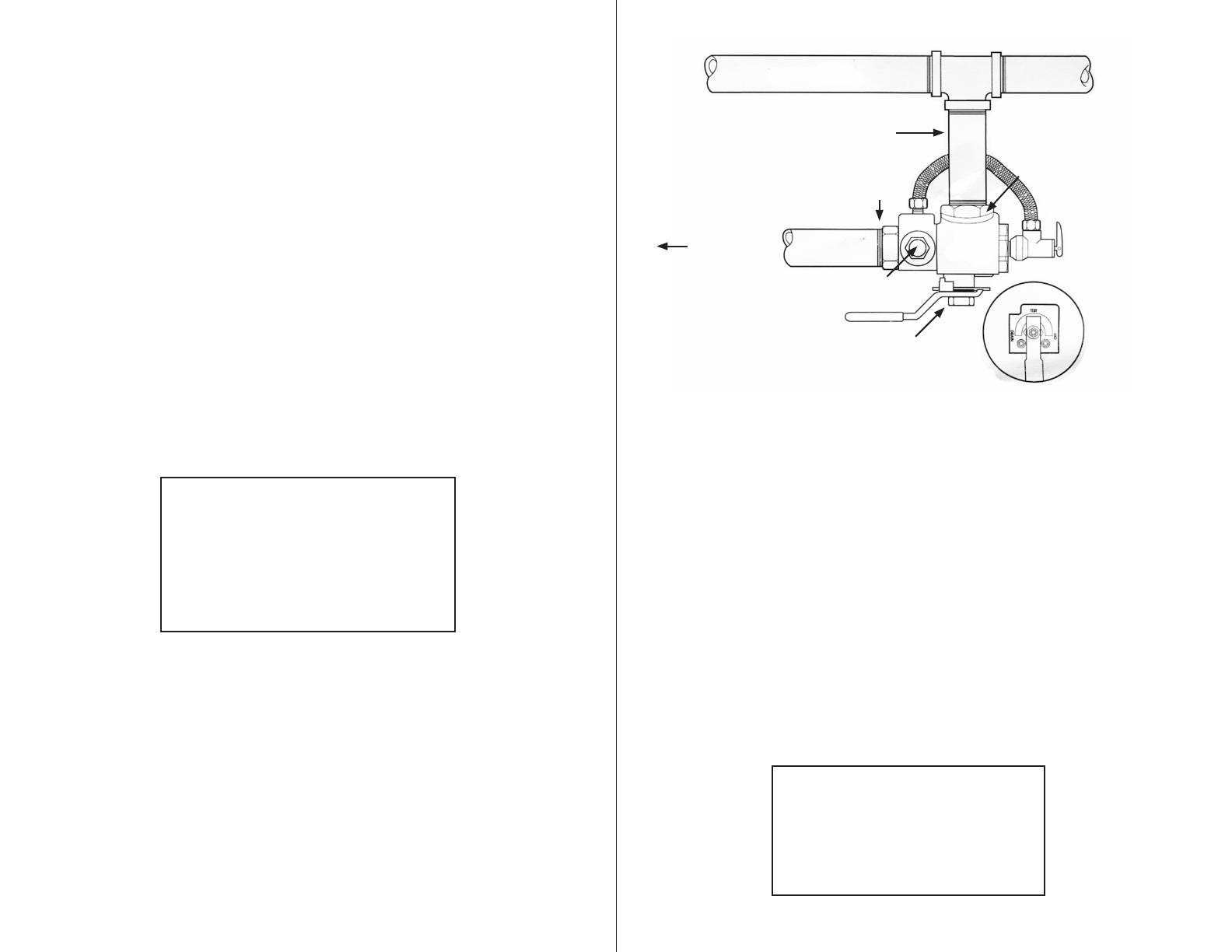
InSTaLLaTIOn InSTRUCTIOnS FOR TESTa n DRaIn
®
1"
anD 1¼" MODEL 2511 VALVE
1. Check the indicating plate for the correct orifice size.
2. Thread the pipe nipple into the inlet of the TESTa n DRaIn.
3. Thread the pipe nipple and the TESTa n DRaIn into the outlet on the feed main.
4. Thread the piping from the outlet of TESTa n DRaIn to an acceptable drain fixture
or active express drain as required.
5. After performing hydrostatic pressure test, remove brass end adaptor plug and
install M7000 pressure relief valve kit (kit included).
For M2511T: Install/tighten ½" x 1½" Nipple, ½" x ½" x ¼" Tee and M7000 Pes-
sure Relief Valve. Install/tighten ½" x 1" Nipple, M7600 3-Way Valve, ¼" Plug,
M7500 Pressure Gauge.
6. Turn the handle on the TESTa n DRaIn to the “OFF” Position.
7. Remove red plug from bypass drain hole under valve body.
8. Install ½" x Barb elbows – one in bypass drain hole and one in outlet of M7000.
9. Install nylobraid tube with clamps between barb elbows. Squeeze clamps with
plyers to seal.
10. Check for leaks by flushing M7000, open M7600 3-Way Valve to read system
pressure.
Feed Main
Nipple
Outlet
To Drain
Site Glass
TESTa n DRaIn
Inlet
CALIFORNIA PROPOSITION 65 WARNING
WARNING: This product contains chemicals
known to the State of California to cause cancer
and birth defects or other reproductive harm.
(Installer: California law requires that this warning
be given to the consumer.)
For more information: www.wattsind.com/prop65


