Safety
Further Information
For further information about our products, please visit www.baumer.com
For technical issues, please contact our technical support:
© Baumer Optronic GmbH · Badstrasse 30 · DE-01454 Radeberg, Germany
Technical data has been fully checked, but accuracy of printed matter is not guaranteed.
The information in this document is subject to change without notice.
Printed in Germany 10/20. v18 11164110
Safety Precautions
Notice
See the User's Guide for the
complete safety instructions!
Caution
Observe precautions for
handling electrostatically
sensitive devices!
▪ Protect the sensor from dirt and
moisture.
▪ Do not allow the camera to become
contaminated with foreign objects.
Environmental Requirements
Storage temp. -10 °C ... +70 °C
Operating temp. see Heat Trans-
mission
Humidity 10 % ... 90 %
Non-condensing
Quick Start Guide
VEXG cameras (Gigabit Ethernet)
System Requirements
Single-camera system
Recommended
Multi-camera system
Recommended
CPU
Intel
®
Core
™
i5-2520M
CPU @ 2.50 GHz, Cores: 4
Intel
®
Core
™
i7-3770
CPU @ 3.40 GHz, Cores: 8
RAM 4 GB 8 GB
Operating
system
(OS)
Microsoft
®
Windows
®
7 (32 / 64 bit systems)
Microsoft
®
Windows
®
8 (32 / 64 bit systems)
Microsoft
®
Windows
®
10 (32 / 64 bit systems)
Product Specication
VEXG cameras – Integrating essential basic functionalities
▪ up to 10 Megapixel
▪ up to 217 fps
▪ 29 × 29 mm housing with all-sided M3 mount
▪ Global shutter architecture for minimized motion blur
▪ Rolling shutter sensors with Global Reset for cost effective applications
▪ Integrating essential basic functionalities
▪ GigE Vision
TM
standard compliant
Notice
Further technical details are available in the respective data sheets.
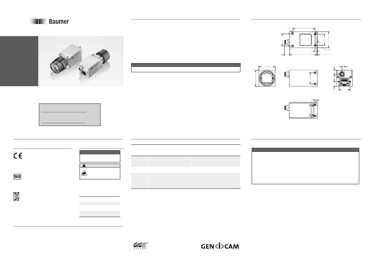
Dimensions
29
29
20
20
4,45
7,2
8,7
20
3
28,7
20
22
40
CS-mount
1,55 ±0,3548,98,9
3
8 x M3 x 4
2 x M3 x 4
ø
1,3±0,35 (VEXG-52 / VEXG-100)
Installation
Lens mount
Notice
Ensure the sensor and lens are not contaminated with dust and airborne
particles when mounting the support or the lens to the device!
The following points are very important:
▪ Install the camera in an environment that is as dust free as possible!
▪ Keep the dust cover (bag) on the camera for as long as possible!
▪ Hold the camera with the sensor downwards if the sensor is uncovered.
▪ Avoid contact with any of the camera‘s optical surfaces!
Download latest camera software:
www.baumer.com/vision/software
Download latest technical documentation:
www.baumer.com/cameras/docs
Conformity
We declare, under our sole responsibility, that the
described Baumer VEXG cameras conform with the
directives of the CE.
All VEXG cameras comply with the recommendation
of the European Union concerning RoHS Rules.
Several of the described Baumer VEXG cameras
conform with the directives of the Korean Conformity.
Please refer for the User’s guide or technical
documentation.

