Page is loading ...

MANUAL FOR INSTALLATION AND USER
MANUAL
v.001 January 2016

2
GB
Via E. Majorana , 49 48022 Lugo (RA) ITALY
“CE” DECLARATION OF CONFORMITY
in compliance with EC Machine Directive 2006/42/EC
It is hereby declared that the air conditioner specified below has been designed and built in compliance with
essential safety and health requisites as per the European Directive on Machine Safety.
This declaration is rendered null and void in the event of incorrect assembly, improper use or modifications
made to the machine without our written approval.
Machine: AIR CONDITIONER
Model: DUALCLIMA 12400 H
Serial n° .........................................
Reference directive:
Machine Directive 2006/42/CE
Low Voltage Directive 2006/95/CE
Electromagnetic compatibility 2004/108/EC
Applied harmonised standards, especially: EN55014-1 ; EN55014-2 ; EN61000-3-2 ; EN61000-3-3 ;
EN62233 ; IEC/EN 60335-1 ; IEC/EN 60335-2-40 ; 2009/19/CE ; DIN EN 378-2
DATE ......25/01/2016.........
C.E.O.

3
GB
CONTENTS
1 INTRODUCTION ........................................................................................................................ 4
1.1 Purpose and field of application of this manual ................................................................. 4
1.2 Key to symbols and definitions .......................................................................................... 4
1.3 General information .......................................................................................................... 4
2 IDENTIFYING THE AIR CONDITIONER .................................................................................... 5
2.1 Components (fig. 1) .......................................................................................................... 5
2.2 ID label ............................................................................................................................. 5
2.3 Technical specifications .................................................................................................... 6
3 TRANSPORT, HANDLING, STORAGE....................................................................................... 6
3.1 Storage ............................................................................................................................. 6
3.2 Weight .............................................................................................................................. 6
3.3 Handling ........................................................................................................................... 6
4 INSTALLATION .......................................................................................................................... 6
4.1 Preliminary information ..................................................................................................... 6
4.2 Installation ........................................................................................................................ 7
4.2.1 Using the existing ventilation port .................................................................................. 7
4.2.2 Opening a new hole....................................................................................................... 8
4.2.3 Power lead .................................................................................................................... 8
4.3 Positioning the air conditioner ........................................................................................... 9
4.4 Connecting the power lead ............................................................................................... 9
4.5 Installing the diffuser ......................................................................................................... 9
5 INSTRUCTIONS FOR USE ...................................................................................................... 10
5.1 Introduction ..................................................................................................................... 10
5.2 Preliminary checks .......................................................................................................... 11
5.3 Useful tips ....................................................................................................................... 11
5.4 Installing batteries in the Remote Control ........................................................................ 12
5.5 Information on Remote Control use ................................................................................ 12
5.6 Remote control key definitions/ functions ........................................................................ 12
5.7 Remote control display (fig. 19) ...................................................................................... 13
5.8 Setting system time on remote control ............................................................................ 13
5.9 Automatic operation mode .............................................................................................. 13
5.10 Cold operation mode ................................................................................................... 14
5.11 Heating operation mode .............................................................................................. 14
5.12 Diffuser Display ........................................................................................................... 14
5.13 Timer setting ............................................................................................................... 14
5.14 Operation without remote control ................................................................................. 15
5.15 Air flow diverter ........................................................................................................... 15
5.16 Cleaning the filters ....................................................................................................... 15
6 SAFETY REGULATIONS ......................................................................................................... 16
7 TROUBLESHOOTING .............................................................................................................. 16
8 DISPOSAL ............................................................................................................................... 17
9 MAINTENANCE ....................................................................................................................... 17
9.1 Routine maintenance ...................................................................................................... 17
GENERAL TERMS OF WARRANTY ........................................................................................... 18
WIRING DIAGRAM ...................................................................................................................... 19
SPARE PARTS LIST .................................................................................................................... 20

4
GB
1 INTRODUCTION
Always consult this
manual carefully before carrying out any
work on the conditioner.
1.1 Purpose and field of application of
this manual
This manual has been drawn up by the
manufacturer in order to provide all the
information / instructions needed for proper,
safe use and maintenance of the air
conditioner.
The manual is an important part of the air
conditioner: it must be stored safely and kept
in good condition throughout the working life
of the machine and protected from
deterioration. It must accompany the air
conditioner if re-installed on a new vehicle or
sold.
The information contained in this manual is
intended for air conditioner installers and all
those involved in its use and maintenance.
The manual defines the purpose for which
the conditioner has been built and contains
all the information required for its safe,
correct use.
Constant observance of the information it
contains will ensure user safety, low running
costs and a longer air conditioner life.
To make consultation easy the manual is
divided into sections, each of which deals
with a specific topic. To find information
quickly refer to the table of contents.
Information of particular importance is
highlighted in bold type and accompanied by
information/warning symbols (see following
key).
You are strongly advised to read the entire
manual and the reference documents: this is
the best way to ensure long-lasting
performance, reliability and prevention of
injury or damage.
Note: the information contained in this
publication was correct at the time of going to
press. Information may be modified without
prior notice.
1.2 Key to symbols and definitions
Indicates risk of serious
injury or death and that the utmost care must
be taken.
Situation that might arise
during the working life of a product, system or
plant which could cause harm, injury,
damage to property or environment or result
in additional expenses.
Indicates that it is
necessary to proceed with due care and
attention to prevent serious damage to
material goods or resources such as the
product itself.
Indicates important
information
Drawings are illustrative only. You may find
that the illustrations differ from the machine in
your possession: this does not in any way
affect the validity of the general / safety
information given in the manual.
As part of its product development and
upgrade policy, the manufacturer reserves
the right to make modifications without prior
notice.
1.3 General information
The DUALCLIMA 12400 H air conditioner
has been designed for installation on vehicle
roofs. It runs on a 230 Vac 50 Hz sinusoidal
power supply.
Power supply voltage
must never drop below
210 Vac and frequency must be stable at
50 Hz.
Using the air conditioner at voltages other
than those indicated could compromise its
efficiency and damage the unit.

5
GB
2 IDENTIFYING THE AIR
CONDITIONER
2.1 Components (fig. 1)
1 Ventilation grilles
2 Upper cover
3 Machine body
4 Technical specifications label
5 Diffuser coupling frame
6 Diffuser
7 Removable ambient air intake filters
8 Adjustable air outflow vents
9 Courtesy lights
10 Diffuser display
11 Remote Control
2.2 ID label
1 Model
2 Serial number
3 Type of electrical power
4 Cooling capacity
5 Heating capacity
6 Type and quantity of coolant gas
7 GWP refrigerant gas
8 Air flow rate
9 Absorbed power, cooling
10 Absorbed power, heating
11 Protection rating
12 Machine weight
The identification plate illustrated is an
example only.
Only the data shown on the actual
conditioner identification plate is valid.
Fig. 1
9
9
8
4
8
7
11
3
1
1
2
5
7
9
10
6
2
4
8
9
1
6
5
3
7
10
11
12

6
GB
2.3 Technical specifications
DUALCLIMA 12400 H
Power supply
230 V 50 Hz
Consumption
6,7 Ampere
Peak current
27 A (0,15 sec.)
Absorbed power, cooling
1520 Watt
Absorbed power, heating
1600 Watt
Cooling capacity
10500 Btu/h
Heating capacity
10900 Btu/h
Type and quantity of coolant gas
R 407c … 650 gr.
N° of fan speeds
3
Air flow rate
480 m
3
/h
Waterproof rating
IP X4
Generator required
2200 W
Diffuser dimensions (H x L x W)
5,4x60x52 cm
Monobloc dimensions (H x L x W)
23,9x98x65 cm
Weight
39 kg
Some of the
technical characteristics in this table may
vary.
Only the data shown on the actual
conditioner identification plate is valid.
3 TRANSPORT, HANDLING,
STORAGE
3.1 Storage
During transport the air conditioner is
protected by its cardboard packaging.
The conditioner must be stored indoors in a
horizontal position in a dry, ventilated area.
The type of packaging allows up to 5 (five)
conditioners to be stacked on top of each
other.
Do not turn the package
upside-down. The right way up is
indicated by the symbol on the packaging
( ↑↑).
Stacking more than five
packaged air conditioners can damage the
conditioners themselves and put
personnel at risk of injury.
3.2 Weight
Weight DUALCLIMA 12400 H, packaging
excluded: 39 kg
3.3 Handling
Packaged air conditioners can be moved
using standard means of lifting and transport.
Always observe safety
and accident prevention
regulations when lifting and transporting.
Use only lifting and transport gear of a
load bearing capacity greater than the
weight to be lifted.
4 INSTALLATION
4.1 Preliminary information
Before installing the
conditioner you must read these
instructions thoroughly to prevent errors.
Incorrect installation can
irreparably damage the air conditioner
and compromise user safety.
European Machine Directive 2006/42/EC
states that the manufacturer cannot be held
liable for poor air conditioner performance
and/or safety should the air conditioner fail to
be installed in observance of the information
provided in this manual. Moreover, the
manufacturer cannot be held liable for any
resulting injury or damage.
Installation must only be
carried out by qualified, specially trained
personnel.

7
GB
4.2 Installation
Before installing the unit
all the following electrical connections on
the vehicle must be disconnected.
• Positive battery lead.
• Generator (where applicable).
• Outdoor power socket.
Failure to observe the
above can lead to power discharges.
Before climbing on top
of the vehicle check that the roof is
designed to be walked on. Check with the
vehicle fitter. If it is not, a scaffolding-like
framework will be required.
To ensure proper air conditioner installation it
is essential that you first check whether the
roof is able to support its weight; if it is not the
roof must be reinforced. Select a fairly flat,
horizontal, central area of the roof and check
that there are no obstacles in the interior
which might obstruct diffuser attachment (fig.
1 ref. 6) or the outflow of cool air from the
adjustable vents (fig. 1 ref. 8).
The air conditioner may be installed in one of
two different ways:
• by using a ventilation aperture already on
the vehicle (ventilation port)
• by opening a new hole.
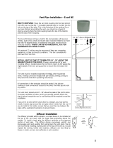
4.2.1 Using the existing ventilation port
This solution is practical as long as the port
size is 395 x 395 mm (fig. 2).
Proceed by removing the screws that fix the
port to the roof and then removing the port
itself.
Scrape off all the sealing material left around
the rim of the opening (fig. 3 ref. 1) and putty
screw holes and joints with silicon or other
products available from specialised shops
(fig. 3 ref. 2).

8
GB
All waste materials (glue,
silicon, seals) must be placed in special
containers and taken to official waste
disposal centres.
4.2.2 Opening a new hole
Choose a central area of the roof between
two side members and trace the outline of a
395 mm square with a felt-tip pen (fig.2) and
(fig. 4 ref. 1).
Cut the new opening in the roof carefully with
a saw: be careful not to cut any electrical
wires (fig. 4 ref. 2).
Fix a reinforcement frame around the
opening (fig. 5).
Use protective gloves and
goggles before using electrical tools or
handsaws.
4.2.3 Power lead
To power the air conditioner it is necessary to
lay a 3-pole lead (phase-neutral-earth): each
wire must have a minimum cross-section
of 2.5 mm
2
. At one end the lead must be
connected to a thermomagnetic switch
inside the electrical distribution board of the
vehicle; the other end must reach the
aperture on the roof, protruding from the hole
on the reinforcement frame by about 50 cm:
this additional length makes it easier to
connect up to the air conditioner (fig. 6).
Before making any
electrical connections always make sure
the power is disconnected inside the
distribution board and that the wire ends
are not live.
6
5
4
1
2

9
GB
It is compulsory for the air conditioner to be
powered via a separate line protected by a 10
A thermomagnetic switch.
To ensure good
insulation under all possible conditions
electrical wiring must be properly
sheathed.
4.3 Positioning the air conditioner
Before installation, check
that the cylindrical section seal on the air
conditioner base is still correctly
positioned inside its special frame seat
(Fig. 7 ref. 1).
Before positioning the air conditioner on the
vehicle roof it is necessary to lay a sufficient
amount of slow-drying sealant around the rim
of the aperture.
Bring the air conditioner onto the roof (fig. 7
ref. 2) and, without scraping it, position it
over the 395 x 395 mm opening previously
lined with sealant. Correct alignment of the
air conditioner on the roof will provide a view
- from inside the camper - of the 4 threaded
fixing seats.
The arrow in fig. 7 indicates direction of
forward drive.
The framed perimeter
support seal must be aligned with the
edge of the hole (fig 7 ref. 1).
Working from inside the vehicle, shift the air
conditioner until the four fixing threads are
aligned with the square 395 x 395 mm
opening of the hole on the roof.
Ensure that the cylindrical seal at the bottom
of the air conditioner is correctly installed in
its seat.
4.4 Connecting the power lead
Connect the 230 Vac power lead to the one
on the just-installed conditioner (fig. 9).
Observe the wire colours:
blue wire: neutral
brown wire: phase
yellow-green wire: earth ( )
Check that the power lead is not
excessively long as it could obstruct the
intake grilles.
4.5 Installing the diffuser
Remove the two air intake filters from the
diffuser by applying pressure towards the
outside (Fig. 10)
Plug the small cable coming from the diffuser
display into the special connector coming

10
GB
from the air conditioner electronic board (Fig.
12).
Position the diffuser horizontally and,
according to your camper roof thickness,
place two or more overlapping coupling
frames (Fig. 14, ref. 1) over the inlet vent
profile (Fig 14, ref. 2). The frames have an
adhesive side to enable the bottom one to
stick to the diffuser and the top ones to stick
to the underlying ones. The frames are
designed to connect the diffuser inlet vent to
the air conditioner outlet.
By using the 4 supplied M6 screws, fix the
diffuser to the bottom of the air conditioner,
locking it to the roof of the camper (Fig. 16).
The screws must be tightened to a torque of
2 N m, i.e. 0.2 Kgm. It is advisable to use a
torque wrench.
Incorrect tightening can
damage the support base of the air
conditioner, compromise the seal and
cause loud noise inside the vehicle when
the conditioner is in operation.
Reassemble the two intake filters that had
been previously removed from the diffuser.
The filters must be pressure-fitted into their
seats.
5 INSTRUCTIONS FOR USE
5.1 Introduction
The manufacturer cannot
be held liable for damage caused by
improper use of the air conditioner.
The DUALCLIMA 12400H air conditioner
consists of nine main parts:
• compressor, which circulates the coolant
gas through the system.
• condenser, which cools the coolant by
changing it from a gaseous to a liquid
state.

11
GB
• evaporator, which, cooled by the change
of state of the coolant, cools the air
passing through it.
• fans, which move the air so that it passes
through the condenser and evaporator
• solenoid valve, which switches gas
circulation and so provides a cooling or
heating function
• remote control to program the desired
function
• receiver, situated in the diffuser, which
receives the remote control signals
• electronic board, which receives the
signals from the receiver and transforms
them into commands for the various
electrical components of the air
conditioner.
The DUALCLIMA 12400H provides cold air
during the summer months and hot air in
winter.
If the vehicle has been left in the sun for
some time it is good practice to open
windows and doors before starting the
conditioner so as to release the build up of
heat in the interior; once indoor temperature
matches outdoor temperature close the
windows and doors and start the air
conditioner. Subsequently, only open doors
and windows when necessary.
5.2 Preliminary checks
Before switching on the air conditioner for the
very first time:
• Check that condensate drainage holes
are unobstructed.
• Check that power voltage and frequency
are as indicated in the previous section.
• Check that air flow through relative ducts
and vents is unobstructed. To ensure
maximum efficiency always keep external
ventilation grilles clear.
When the equipment is
started for the first time with the remote
control, the fan and compressor will also
start within a few seconds. After a power-
off, upon the next power-on the
compressor will only start after at least 3
minutes from the power-off.
5.3 Useful tips
• Enhance the thermal insulation of the
camper by eliminating any fissures and
covering glass surfaces with heat-
reflecting curtains.
• Avoid frequent opening/closing of
windows unless necessary.
• Select a suitable temperature and airflow
rate.
• Adjust the outflow vents to maximise
comfort.
• Never close both adjustable vents when
the conditioner is running.
• Wait at least 2 minutes between switching
off and switching on so as not to damage
the compressor.
• Clean the diffuser filters periodically;
wash them with a detergent solution and
dry them thoroughly before refitting them.
• Do not obstruct airflow inlets/outlets with
fabric, paper or anything else.
• Do not spray water inside the air
conditioner.
• Remove the remote control battery if you
do not intend to use the conditioner for a
long period.
• Periodically check that the condensate
drain holes are not obstructed.
• Periodically check that external intakes
grilles are clean so as to maintain
maximum air conditioner efficiency.
• Clean the air conditioner with detergent
solutions only; never use petrol or
solvents.
• If the vehicle is garaged for the winter
disconnect the air conditioner from the
power socket.

12
GB
5.4 Installing batteries in the Remote
Control
1. Remove the cover
by sliding it in the
direction indicated
by the arrow.
2. Insert two new 1.5
V AAA batteries:
observe polarity (+
and -).
3. Replace the cover.
5.5 Information on Remote Control use
• Point the remote control towards the
internal unit of the conditioner.
• There must be no obstructions between
the remote control and the internal unit.
• Do not drop or throw the remote control.
• Do not expose the remote control to direct
sunlight or leave it near heating systems
or other sources of heat.
• Use two AAA batteries.
• If you do not intend to use the remote
control for some time, remove the
batteries.
• When the control reception sound signal
is no longer audible in the indoor unit, or
when the transmission symbol on the
display screen is no longer clearly visible,
the batteries need replacing.
• If the remote control unit resets when a
key is pressed, battery power is too low:
the batteries need replacing.
5.6 Remote control key definitions/
functions
1 - Secondary keys access flap
2 - Display (see Fig. 19)
3 - On/Off control to start/stop the air
conditioner.
4 - +TEMP and -TEMP to set the required
temperature between 16 and 31 °C.
18
1
2
3
5
4
8
6
7
10
11
9
12

13
GB
5 - LIGHT key, it enables the courtesy lights
on the diffuser to be turned on and off
6 – FAN enables to select one of three
available speed settings, or it can be left to
the conditioner to select the most suitable
setting.
7 - MODE enables to select the Automatic,
Cold or Hot operation mode.
8 - TIMER enables to activate the timer
function and set the air conditioner start and
stop times
9 - +HOUR and –HOUR to set the remote
control time and timer function start and stop
times.
10 - SET to access the remote control time
adjustment mode or validate the timer
function start and stop times.
11 - CLEAR deletes the timer function
programming.
12 - RESET to control a remote control total
reset (hidden button to press with a small
sharp object).
5.7 Remote control display (fig. 19)
1. Automatic mode
2. Cold operation mode
3. Hot operation mode
4. Function not supported
5. Data transmission indicator
6. Timer: start time (only visible if the timer
has been activated)
7. Timer: stop time (only visible if the timer
has been activated)
8. System time
9. Courtesy light on indicator
10. Set temperature
11. Function not supported
12. Set ventilation speed indicator (if the
AUTO message is displayed, speed is
automatically managed by the air
conditioner)
5.8 Setting system time on remote
control
After inserting the batteries, set the system
time on your remote control:
• Press and hold down the SET key on
your remote control until the system time
digits start flashing
• By using the +HOUR and –HOUR keys,
set your system time
• Press the SET key once again
5.9 Automatic operation mode
1) Press the On/Off key
2) Press the MODE key repeatedly until the
display shows the Automatic mode
symbol
3) Set your required temperature with the
keys +TEMP and –TEMP
4) Press the FAN key several times until
you reach your required ventilation
setting.
19
1
2
5
7
6
8
9
10
11
3
4
12

14
GB
5.10 Cold operation mode
1) Press the On/Off key
2) Press the MODE key repeatedly until
the display shows the COLD mode
symbol.
3) Set your required temperature with the
keys +TEMP and -TEMP.
4) Press the FAN key several times until
you reach your required ventilation
setting.
5.11 Heating operation mode
1) Press the On/Off key
2) Press the MODE key several times until
the display shows the HOT mode symbol.
3) Set your required temperature with the
keys +TEMP and -TEMP.
4) Press the FAN key several times until you
reach your required ventilation setting.
In Heating mode the air
conditioner is effective with outside
temperatures down to -2°C, while below
this value, delivery efficiency is
considerably reduced.
If the air conditioner
is turned off during the heating mode,
the fan will remain in operation for a
few minutes in order to dissipate the
heat accumulated inside the air
conditioner, before stopping
automatically.
5.12 Diffuser Display
The diffuser has a display which also
incorporates the remote control IR receiver.
When the red Power light (Fig. 20 ref. A) is lit
on the display the air conditioner is powered
off 230 Vac line power.
When the green Run light (Fig. 20 ref. B) is
lit, the air conditioner is working in Cold
mode; if the red Run light is lit, the air
conditioner is working in Heating mode.
The two figures (Fig. 20 ref. C) normally refer
to the ambient temperature measured by the
air conditioner inside the camper.
During the required temperature setting
procedure with the remote control, the display
unit will show the currently selected
temperature; after approximately 30 seconds
from the end of the selection procedure, the
display will show the camper indoor
temperature again.
5.13 Timer setting
• Press the TIMER key on the remote
control: the start time ON indicator is
activated
• By using the +HOUR and –HOUR keys,
set the start time
• Press the TIMER key once again: the stop
time OFF indicator is activated
• By using the +HOUR and –HOUR keys,
set the stop time
• Press the TIMER key once again
• After completing the setting operations,
press the SET key
To delete timer programming press the
CLEAR key
The start and stop
times are programmable in 10 minutes'
steps.

15
GB
5.14 Operation without remote control
If the remote control is lost or not working, it
is still possible to use the air conditioner by
pressing with a sharp object the small Reset
key hidden inside the slot between the AUTO
and TEST labels next to the display (Fig. 22
ref. D).
By pressing the key, the air conditioner is
started in the automatic mode, automatic fan
mode, temperature setting 24 °C.
5.15 Air flow diverter
A flap door is provided on the diffuser. Below
it is a control knob (Fig. 24, ref. A) which can
be loosened to adjust the direction of the air
flow out of the front and rear vents.
5.16 Cleaning the filters
To ensure top efficiency for the conditioner,
regularly clean both diffuser filters. Whenever
removing any dust build-up is insufficient,
wash the filters with a mild detergent solution,
then allow them to dry completely before
placing them back in the diffuser.

16
GB
6 SAFETY REGULATIONS
• Always use properly earthed power
sockets with differential safety switches.
• Never use the air conditioner near
flammable liquids.
• Do not use the air conditioner for
purposes other than those stated by the
manufacturer.
• Do not modify or tamper with any parts of
the air conditioner.
• Use only original spare parts.
• Maintenance and repairs must only be
carried out by specialised personnel.
• Installation must be carried out by
qualified personnel.
• Keep children/animals away from the air
conditioner unit.
• Do not insert hands/fingers in ventilation
grilles/vents.
• Do not insert objects into ventilation
intakes.
• If the air conditioner receives any hard
knocks have it checked by specialised
personnel before using it again.
• In the event of fire never open the upper
cover of the conditioner: use homologated
fire extinguishers.
• Do not attempt to put out a fire with water.
7 TROUBLESHOOTING
In the majority of cases poor air conditioner
performance is caused by incorrect use as
opposed to actual malfunctions. For example:
• The unit is too small for the volume of air
you wish to condition.
• The vehicle is poorly insulated.
• The doors are opened too frequently.
• There are too many people inside the
vehicle.
• Power supply voltage is less than 230 V.
The following is a list of the most common
problems with corresponding causes and
solutions.
In the event of air
conditioner malfunctioning, before carrying
out any conditioner servicing check::
• the power supply is never less than 205
V.
• that intake vents are unobstructed.
• that air outflow vents are open.
1) The air conditioner does not start:
• check that the remote control batteries
are charged properly.
• Check that the system is electrically live
by connecting another household
appliance or using a voltmeter
2) Air outflow is insufficient:
• check that the directional vents are open
enough
• check that the diffuser filters are clean
enough
3) Air conditioning (cooling) is not
working:
• check that temperature setting is lower
than actual in-camper temperature.
4) Heating is not working:
• check that temperature setting is higher
than actual in-camper temperature.
5) Air conditioner efficiency is poor
• if the air conditioner is working
inefficiently it is necessary to clean the air
filter, condenser and evaporator using
specific detergents. It is always advisable
to clean the air conditioner when it has
remained idle for a long period.
• if, after cleaning the exchangers, the air
conditioner still fails to return to its initial
level of efficiency, then the coolant gas
load must be checked.

17
GB
8 DISPOSAL
Always contact specialised workshops when
it is necessary to dismantle and dispose of
the air conditioner.
Waste materials must
not be dispersed into the environment:
always take them to authorised waste
collection centres
9 MAINTENANCE
9.1 Routine maintenance
All tasks requiring removal of air conditioner
covers must – as with installation - be carried
out by expert personnel
Before carrying out any
work on the air conditioner it is essential
that you disconnect the 230 V power
supply and wait for all its component
parts to cool down.
• Remove the external cover and spray a
suitable detergent onto the heat
exchangers (evaporator and condenser)
and then rinse to remove impurities.
Check that the condensate drain holes
are unobstructed.
• Check that the seals are in good condition
and there is no infiltration of water into the
vehicle.
• All traces of oxidation must be removed
and metallic parts coated with a suitable
paint.
• Check that wiring insulation is in good
condition and eliminate any traces of
moisture.
• Check that all screws are properly
tightened.

18
GB
GENERAL TERMS OF WARRANTY
TELAIR guarantees its products against any construction material and/or
manufacturing faults and defects.
The right to warranty cover for new products is valid for a period of 24
months fr
om the time of handing over to the end user, or for a maximum of
1000 operating hours, whichever limit is reached first. In all cases the
warranty period shall end no later than 26 months (28 months if delivered
outside of Europe) after ex factory delivery.
For electric and hydraulic components, pipes, belts, sealing elements,
injection nozzles, clutches, drives, the warranty term is 12 months from the
time of handing over to the end user, or a maximum of 1000 operating
hours, whichever limit is reached fi
rst. In all cases the warranty period
shall end no later than 14 months (16 months if delivered outside of
Europe) after ex factory delivery.
In any case, the costs of lubricants and consumables shall be charged.
Any transport expenses shall have to be covered by the purchaser; the same
applies to any expenses connected with inspections requested by the customer
and accepted by TELAIR.
The manufacturer’s warranty shall only be valid if:
• the customer has carried out all routine maintenance according to the
recommended schedule and has promptly visited the nearest after-sale centre
if required.
• the customer can produce a document showing the date of sale (invoice or
receipt).
Such document will have to be kept with care and be intact when produced to
the TELAIR After-Sales centre on requesting service.
In any case, the purchaser shall not be entitled to:
• terminate the contract;
• claim damages to persons or property;
• ask that the warranty be extended in the event of product defects or
malfunctioning.

19
GB
WIRING DIAGRAM

20
GB
SPARE PARTS LIST
/