Page is loading ...

E-M-HG2-S-XL-V3.0
Rotronic AG
Bassersdorf, Switzerland
Document code
Unit
HygroGen2: Humidity and Temperature Generator
with AutoCal, MBW External Reference, Remote Screen
Share, RemoteAPI and Range Extension options.
Instruction Manual
Instruction Manual for Software
Version 3.0
Document Type
Document title
© 2009-2018; Rotronic AG E-M-HG2-S-XL-V3.0
Instruction Manual
HG2-S and HG2-XL

E-M-HG2-S-XL-V3.0
Rotronic AG
Bassersdorf, Switzerland
Document code
Unit
HygroGen2: Standard Supply Package
Advisory Notice
Document Type
Document title
© 2009-2018; Rotronic AG E-M-HG2-S-XL-V3.0
Contents of the Standard Supply Package HG2-S:
• HG2-S HygroGen2 generator
• HG2-DES Desiccant cell filled with molecular sieve (pre-installed)
• IEC mains cable
• HG2-FILL Water fill syringe (with tube)
• HC2-S-S HC2-S control probe (pre-installed) with calibration certificate
1
• Sample Loop connector cover plugs
• This Manual
• Chamber door (according to customer's order)
2
• HW4 software ID number
• USB memory stick including saved test data and user manual
Contents of the Standard Supply Package HG2-XL:
• HG2-XL HygroGen2 generator with integrated door
• 2 x HG2-DES Desiccant cells filled with molecular sieve (pre-installed)
• IEC mains cable
• HG2-FILL Water fill syringe (with tube)
• HC2-S-S HC2-S control probe (pre-installed) with calibration certificate
1
• Sample Loop connector cover plugs
• This Manual
• HW4 software ID number
• USB memory stick including saved test data and user manual
1
The calibration certificate included will vary according to the country of supply.
2
In some countries, the chamber door is delivered with the HygroGen2. Due to the diversity of chamber doors
and bungs, these are normally ordered separately and may be delivered in separate packaging.

E-M-HG2-S-XL-V3.0
Rotronic AG
Bassersdorf, Switzerland
Document code
Unit
HygroGen2: Table of Contents
Table of Contents
Document Type
Document title
© 2017; Rotronic AG E-M-HG2-S-XL-V3.0
1 Scope of Document 6
1.1 Introducing the HygroGen2 6
1.2 Temperature and Humidity References 6
1.3 Optional Enhanced Features: AutoCal, External Reference,
Range Extensions and Remote Control 7
2 Setting up the HygroGen2 9
2.1 Physical Location 9
2.2 Electrical Supply 9
i. Power Isolation 9
ii. Earthing 9
iii. Earth Leakage Current 9
iv. Overcurrent Protection 9
v. Voltage Rating 9
vi. Mains Filtration 10
vii. Conductive Pollution 10
2.3 HygroGen2 Assembly 11
HG2-S 11
i. HygroGen2-S Doors 12
ii. Desiccant Cell 12
iii. External Sample Loop 12
iv. HC2-S Control Probe 12
HygroGen2-XL 13
i. HygroGen2-XL Door 14
ii. HygroGen2-XL Shelves 14
iii. HygroGen2-XL Cable Management 15
iv. Desiccant Cells 15
v. External Sample Loop 16
vi. HC2-S Control Probe 16
2.4 Water Reservoir 17
i. To fill the HygroGen2: 17
ii. To empty the HygroGen2: 18
iii. Ultra-violet sterilisation lamp 18
3 HygroGen2 - Basic Operation 19
3.1 Switching On 19
3.2 Upgrading HygroGen2 Firmware 20
Updating HygroGen2 firmware from earlier version 1.x or 2.x 20
Updating HygroGen2 firmware from earlier version 3.x 20
Updating HW4 version 24
3.3 Configuration Mode Settings 27
Network Settings 27
Date and Time Settings 29
International Keyboard 29
External Monitor 29
Touch Screen Calibration 30
3.4 HygroGen2 Touchscreen Interface 31
Controller Home Screen 31
i. Navigation (items 1, 10 & 14) 31

E-M-HG2-S-XL-V3.0
Rotronic AG
Bassersdorf, Switzerland
Document code
Unit
HygroGen2: Table of Contents
Table of Contents
Document Type
Document title
© 2017; Rotronic AG E-M-HG2-S-XL-V3.0
ii. Temperature and Humidity Set-Points (items 3 & 7) 32
iii. Temperature and Humidity Control (items 5 & 9) 32
Trend Screen 33
i. Trace selection (item 4) 33
ii. Trend Axes (items 2 & 3) 33
Programmer Screen 34
i. Program Selection (items 1 & 2) 34
ii. Step Selection (item 3) 34
iii. Run/Stop (item 4) 34
iv. Edit Program (item 5) 35
Edit Program Screen 35
i. Select a Program to Edit 35
ii. Edit a Program Name 35
iii. Edit a Step 35
iv. Insert or Delete a Step (items 6 & 7) 36
v. Ramp or Soak (item 2) 36
vi. Timing Tolerances (items 10 & 11) 36
vii. Temperature only Program (item 12) 36
viii. Programmer Screen 36
Settings Screen 37
i. Activation of Enhanced Features 37
ii. HygroGen Information 38
iii. Remote Support 38
iv. Connections to Network File Servers 40
4 HygroGen2 Enhanced Features 41
4.1 AutoCal 43
Top Level Menu and Programmer Function 43
AutoCal Reference 43
AutoCal Screen 43
AutoCal Program Edit 44
Tolerance and Sample Size 45
AutoCal Operation and Best Practices 45
Customising the PDF Calibration Certificate 47
Reference Information 48
4.2 External MBW/RH Systems Calibration Reference (AutoCal+) 49
Connecting and Configuring MBW/RHS External Reference 50
Measurement Type and Corrections 53
Corrections 54
Calibration Info 55
Advanced (Command Line interface) 55
Best Practices and Precautions 55
i. Dew/Frost control 56
ii. Mirror Cleaning 56
iii. Decontamination of HygroGen2 chamber 56
iv. Super Cooled Water: Dew or Frost Films. Force Frost Threshold 56
v. Extremes of Temperature and Humidity 57
4.3 Remote Control 57

E-M-HG2-S-XL-V3.0
Rotronic AG
Bassersdorf, Switzerland
Document code
Unit
HygroGen2: Table of Contents
Table of Contents
Document Type
Document title
© 2017; Rotronic AG E-M-HG2-S-XL-V3.0
Remote Screen Share 57
RemoteAPI 60
4.4 Range Extensions 64
5 General Operational Considerations 65
Water in the Chamber 65
Below Ambient Temperature Operation 65
Above Ambient Temperature Operation 66
Probe Insertion Depth 66
Protective Filters 67
Low Water Level Alarm 67
Water Level Indicator Calibration 67
5.2 Switching off the HygroGen2 68
Shut Down 69
Transit 69
5.3 Preparing the Unit for Transit or Storage 70
6 HW4 Embedded 71
6.1 HW4 Set Up and Getting Started 71
6.2 HW4 Installation and Registration 72
6.3 HW4 Support 72
6.4 Data Logging in HW4 73
Test Instrument Data 73
Control HC2-S 74
7 External PC Peripherals 75
7.1 USB Keyboard and Mouse 75
International Keyboard Layouts 75
7.2 External Monitor 76
8 Servicing and Maintenance 77
8.1 Control HC2-S Calibration 77
Removing Control HC2-S HG2-S 77
Removing Control HC2-S HG2-XL 77
8.2 Desiccant 78
Changing Desiccant 79
Choice of Desiccant 80
8.3 HygroGen2 Cleaning 81
External surfaces 81
Air Inlet Filters – HG2-S 81
Air Inlet Filters – HG2-XL 81
Chamber 82
Purging internal pipes 82
8.4 Annual Servicing of HygroGen2 82
A1: Calibration Reference Options 83
A1.1 Internal RH Probe Reference 83
A1.2 External RH Probe Reference 84
A1.3 Chilled Mirror Reference 84
A2: Temperature Control 87
A3: Validation – Requirements and Accessories 88

E-M-HG2-S-XL-V3.0
Rotronic AG
Bassersdorf, Switzerland
Document code
Unit
HygroGen2: Table of Contents
Table of Contents
Document Type
Document title
© 2017; Rotronic AG E-M-HG2-S-XL-V3.0
B2: HygroGen2 / Screen Messages 90
B3: HygroGen2-S Specification 91
B4: HygroGen2-XL Specification 92
B5: HygroGen2 Order Codes: 93
C1: HygroGen2 Warranty Statement 96
C2: Manufacturer & Service Centre Contact Information 97
D1: HygroGen2 Uncertainty Framework - Internal RH Probe 98
D2: HygroGen2 Uncertainty Framework - External RH Probe 99
D3: HygroGen2 Uncertainty Framework - Chilled Mirror Reference 100
D4: Dew Point Uncertainty Analysis 101

E-M-HG2-S-XL-V3.0
Rotronic AG
Bassersdorf, Switzerland
Document code
Unit
HygroGen2: Humidity and Temperature Generator
with AutoCal, MBW External Reference, Remote Screen
Share, RemoteAPI and Range Extension options.
Instruction Manual
Instruction Manual for Software
Version 3.0
Document Type
Page
6 of 102
Document title
© 2017; Rotronic AG E-M-HG2-S-XL-V3.0
1 Scope of Document
This instruction manual refers to both HygroGen2 models: HG2-S and HG2-XL, running
software version 3.0. To determine the software version that your instrument is running, please
refer to the Settings Screen as shown in section 3.4.5. For version 1.x.x, the software revision
number is displayed by pressing the “HG Info” button; for version 2.0, select “Info” from the
“Service” drop-down menu; for version 2.1 and later, select “HygroGen2 Info” from the
“Support” drop-down menu. Equivalent manuals are available on www.rotronic.com for
HygroGen2 instruments running software versions 1.x. and 2.x.
For instructions on how to upgrade to version 3.0 please see Section 3.2.
1.1 Introducing the HygroGen2
The HygroGen2 is a generator of controlled relative humidity and temperature environments,
primarily for use in calibrating humidity instrumentation, but is also well suited to the
calibration of temperature instrumentation, particularly those used for the measurement of
temperature in air.
It is a completely self-contained, portable unit requiring no external resources except mains
power. This allows technicians to perform calibrations in the laboratory, workshop or on-site.
The HygroGen2 is available in the standard HG2-S version - with 2 litre chamber – and, as of
2016, a larger HG2-XL - with 20 litre chamber.
The HygroGen2 uses a mixed flow method for generating the %rh required by the user. A
desiccant cell provides a source of low humidity and a piezoelectric humidifier generates high
humidity. A Peltier element is used for heating and cooling the chamber. Measurement and
control is provided by a combination of a ROTRONIC HC2-S probe, an embedded Platinum
Resistance Thermometer (PRT) and a multi-loop controller. Set-points are entered using the
touchscreen front panel display.
1.2 Temperature and Humidity References
The HygroGen2 creates stable temperature and humidity conditions uniformly within its test
chamber. Instruments under test (IUTs) are inserted through the chamber door, or placed
directly inside, and compared to a reference to calibrate and monitor their performance so that
any appropriate adjustments can be made.

E-M-HG2-S-XL-V3.0
Rotronic AG
Bassersdorf, Switzerland
Document code
Unit
HygroGen2: Humidity and Temperature Generator
with AutoCal, MBW External Reference, Remote Screen
Share, RemoteAPI and Range Extension options.
Instruction Manual
Instruction Manual for Software
Version 3.0
Document Type
Page
7 of 102
Document title
© 2017; Rotronic AG E-M-HG2-S-XL-V3.0
There are three main relative humidity (RH) calibration reference types that can be used with
the HygroGen2. Each has its own advantages and disadvantages, so the reference chosen
should be determined by the uncertainty of measurement required.
• Internal control RH probe reference
• External RH probe reference
• Chilled Mirror Hygrometer reference
Corresponding temperature references integrated in the above may be used or additional
external temperature references employed (for example, platinum resistance thermometers
(PRTs)).
It is vital to consider the comparison of temperatures measured by the reference, the
HygroGen2 and IUTs. Because RH is significantly dependent on temperature, temperature
measurement should be optimised to get meaningful RH results.
For more details, please see A1: Calibration Reference Options and Appendices D1 to D4 on
Uncertainty.
1.3 Optional Enhanced Features: AutoCal, External Reference, Range
Extensions and Remote Control
With the introduction of software version 2.0, the HygroGen2 comes with optional Enhanced
Feature upgrades: AutoCal and RH/Temperature Range Extensions. Version 2.1 has more
additions to the Enhanced Features range: AutoCal+ and Remote Control. Further
enhancements are in development and will be released in subsequent versions.
All Enhanced Features are activated by the application of a licence key, available via your
ROTRONIC dealer, and can be added to any HygroGen2. Older units with serial numbers prior
to HG2-VCT-1280 may require a service in order to enable network features required for
Remote Control.
Low Temperature and Humidity Range Extensions extend the limits of points that can be
set on the instrument, creating chamber conditions down to -5 °C and from 2 %rh up to
99 %rh.
AutoCal allows you to pre-program a series of set-points and times, and record the
instrument‘s progression through them in a PDF Calibration Certificate which is written to an
external USB disk drive. Any values recorded on ROTRONIC HC2-S probes attached to the
HygroGen2 via USB adaptors are recorded in the certificate. Probes can be set to automatically
adjust to match the HygroGen2 reference probe at predetermined values.

E-M-HG2-S-XL-V3.0
Rotronic AG
Bassersdorf, Switzerland
Document code
Unit
HygroGen2: Humidity and Temperature Generator
with AutoCal, MBW External Reference, Remote Screen
Share, RemoteAPI and Range Extension options.
Instruction Manual
Instruction Manual for Software
Version 3.0
Document Type
Page
8 of 102
Document title
© 2017; Rotronic AG E-M-HG2-S-XL-V3.0
Remote Screen Share (Formerly Remote Control) gives the ability to remotely control the
HygroGen2 over a network using the open source VNC protocol.
RemoteAPI gives the ability to remotely control and interrogate the HygroGen2 using a series
of text based commands over a network; users can write their own software to log and control
the HygroGen2.
MBW External Reference (formerly AutoCal+) extends the functionality of AutoCal and
RemoteAPI, by integrating MBW/RHS chilled mirror hygrometers (supplied separately) as the
external reference.

E-M-HG2-S-XL-V3.0
Rotronic AG
Bassersdorf, Switzerland
Document code
Unit
HygroGen2: Humidity and Temperature Generator
with AutoCal, MBW External Reference, Remote Screen
Share, RemoteAPI and Range Extension options.
Instruction Manual
Instruction Manual for Software
Version 3.0
Document Type
Page
9 of 102
Document title
© 2017; Rotronic AG E-M-HG2-S-XL-V3.0
2 Setting up the HygroGen2
2.1 Physical Location
To ensure correct operation please ensure that:
1. The unit is level and stable;
2. There is at least 15 mm clearance underneath and at least 100 mm at the back of the unit to enable
adequate air flow;
3. There is adequate access to the electrical mains connection at the rear of the unit.
Note: The feet on the rear panel are for standing the unit for service purposes and to ensure a
sufficient air gap behind the unit. The unit will not operate in the vertical position.
2.2 Electrical Supply
i. Power Isolation
The unit is supplied with a mains cord set. The unit should be disconnected from the electrical
supply before the unit is moved, cleaned or has water added or removed.
ii. Earthing
This unit must be earthed. Provision for the safety earth is made through the electrical mains
connection (see Figure 2(8) below) to which all parts of the unit requiring earthing are
internally connected. An earthed electrical supply is required.
iii. Earth Leakage Current
Due to RF filtering, there is an earth leakage current, within the limits specified in EN 61010-
1:2001. This may affect mains power circuits protected by Residual Current Device (RCD) or
Ground Fault Detector (GFD) type circuit breakers (particularly if used in multiples or with
other equipment with an earth leakage current on the same supply circuit).
iv. Overcurrent Protection
To protect the internal circuitry against excess currents, the mains supply to the unit must be
connected with the mains cord set provided with the unit and to an appropriate mains supply.
v. Voltage Rating
The unit is designed to work within the limits of a 110-230 VAC 50-60 Hz mains supply with
voltage fluctuations up to ± 10% of the nominal voltage. The unit is rated impulse-withstand
(overvoltage) category II of IEC 60364-4-443. Where occasional voltage transients over 2.5 kV
are expected or measured, it may be necessary that the power installation to the unit includes a
transient limiting device.

E-M-HG2-S-XL-V3.0
Rotronic AG
Bassersdorf, Switzerland
Document code
Unit
HygroGen2: Humidity and Temperature Generator
with AutoCal, MBW External Reference, Remote Screen
Share, RemoteAPI and Range Extension options.
Instruction Manual
Instruction Manual for Software
Version 3.0
Document Type
Page
10 of 102
Document title
© 2017; Rotronic AG E-M-HG2-S-XL-V3.0
vi. Mains Filtration
If there is risk of power spikes or breaks, it is recommended that an Uninterruptable Power
Supply (UPS) is used to provide continued power and mains filtration. This should be rated
according to the HygroGen2 power specifications (see Appendix B3) and the time required to
run/shut down during power outage.
vii. Conductive Pollution
The unit is rated Pollution Degree 2 and must not be operated in environments where
conductive pollutants (for example, carbon) may enter the unit. This includes excessive
moisture ingress.

E-M-HG2-S-XL-V3.0
Rotronic AG
Bassersdorf, Switzerland
Document code
Unit
HygroGen2: Humidity and Temperature Generator
with AutoCal, MBW External Reference, Remote Screen
Share, RemoteAPI and Range Extension options.
Instruction Manual
Instruction Manual for Software
Version 3.0
Document Type
Page
11 of 102
Document title
© 2017; Rotronic AG E-M-HG2-S-XL-V3.0
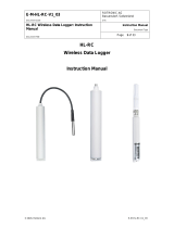
2.3 HygroGen2 Assembly
HG2-S
1) Power switch
2) USB ports (7) (8
3) Touch screen controller
4) Water port
5) Desiccant cell
6) Chamber door
7) Probe aperture bung
8) Handle
1) Sample loop return
2) Sample loop outlet
3) USB ports (2)
4) DVI monitor interface
5) Ethernet socket
6) Type label
7) Fan outlet
8) Electrical mains connection
9) Power switch
Figure 1: Front of HygroGen2-S
Figure 2: Rear of HygroGen2-S

E-M-HG2-S-XL-V3.0
Rotronic AG
Bassersdorf, Switzerland
Document code
Unit
HygroGen2: Humidity and Temperature Generator
with AutoCal, MBW External Reference, Remote Screen
Share, RemoteAPI and Range Extension options.
Instruction Manual
Instruction Manual for Software
Version 3.0
Document Type
Page
12 of 102
Document title
© 2017; Rotronic AG E-M-HG2-S-XL-V3.0
i. HygroGen2-S Doors
The HygroGen2-S does not come supplied with a door. There are various standard and
customized versions available, depending on the intended use for the instrument, the use of an
external reference (see Appendix A1.2) and the instruments under test. Figure 1(6) above
shows the 15 mm 5-port version (part code: HG2-D-11111). Other options are listed in
Appendix B4.
To access the HygroGen2 chamber, remove the door. Grip firmly and twist the door anti-
clockwise. In the event that this proves difficult, cool the chamber first. Occasional instrument
application of silicone grease around the door “O” ring seal will ease movement.
Replacement can be in any position and requires only a gentle clockwise twist.
Before using your HygroGen2, make sure that the door is secured and that all probe apertures
not in use are sealed with a bung (see Figure 2(7) above) or an appropriate alternative seal.
ii. Desiccant Cell
The unit should be supplied with the desiccant cell in place (see Figure 1(5) above). For further
details and best practice for desiccant handling, please see section 8.2.
iii. External Sample Loop
Unless an external sampling system is to be used
(see “External Sample Loop Operation” in Appendix A1.3),
ensure the sample loop caps (Figure 2(1) and (2) above) are firmly secured.
iv. HC2-S Control Probe
The HygroGen2 chamber conditions are monitored and controlled by a ROTRONIC HC2-S
HC2-S-S RH and temperature probe. Depending on the circumstances and whether external
references are being used (see Appendix A1.2 External RH Probe Reference), this probe may
need to be removed for regular calibration.
See Section 8.1.1 for details on removing the control HC2-S probe.
Note: For speed of response, this probe must be employed without a protective filter.

E-M-HG2-S-XL-V3.0
Rotronic AG
Bassersdorf, Switzerland
Document code
Unit
HygroGen2: Humidity and Temperature Generator
with AutoCal, MBW External Reference, Remote Screen
Share, RemoteAPI and Range Extension options.
Instruction Manual
Instruction Manual for Software
Version 3.0
Document Type
Page
13 of 102
Document title
© 2017; Rotronic AG E-M-HG2-S-XL-V3.0
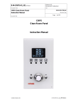
HygroGen2-XL
1) Power switch
2) USB ports (7) (7)
3) Touch screen controller
4) Water port
5) Desiccant cell
6) Chamber door
7) Probe aperture bung
8) Chamber door handle
1) Sample loop return
2) Sample loop outlet
3) USB ports (2)
4) DVI monitor interface
5) Ethernet socket
6) Type label
7) Fan inlets and filter covers
8) Electrical mains connection
9) Power switch
Figure 3: Front of HygroGen2-XL
Figure 4: Rear of HygroGen2-XL

E-M-HG2-S-XL-V3.0
Rotronic AG
Bassersdorf, Switzerland
Document code
Unit
HygroGen2: Humidity and Temperature Generator
with AutoCal, MBW External Reference, Remote Screen
Share, RemoteAPI and Range Extension options.
Instruction Manual
Instruction Manual for Software
Version 3.0
Document Type
Page
14 of 102
Document title
© 2017; Rotronic AG E-M-HG2-S-XL-V3.0
i. HygroGen2-XL Door
The HygroGen2-XL is supplied with a door, though customised versions are available. At the
time of preparing this manual, the standard configuration has 8 x 30 mm ports; there is also a
19 x 30 mm port version available.
Before using your HygroGen2, make sure that the door is secured and that all probe apertures
not in use are sealed with a bung or an appropriate alternative seal.
ii. HygroGen2-XL Shelves
The HygroGen2-XL has three removable shelves, which secure into clips at the back of the
chamber and rest on lugs at the front. Secure each shelf into the clips at the back and lower the
front of the shelf into place.
Figure 5: HygroGen2-XL with 19 x 30mm ports
Figure 6: HygroGen2-XL shelving system

E-M-HG2-S-XL-V3.0
Rotronic AG
Bassersdorf, Switzerland
Document code
Unit
HygroGen2: Humidity and Temperature Generator
with AutoCal, MBW External Reference, Remote Screen
Share, RemoteAPI and Range Extension options.
Instruction Manual
Instruction Manual for Software
Version 3.0
Document Type
Page
15 of 102
Document title
© 2017; Rotronic AG E-M-HG2-S-XL-V3.0
iii. HygroGen2-XL Cable Management
For devices placed wholly inside the chamber, it is recommended to secure cables to the
shelves using cable-ties and run the cables through a spare port in the door. The port can be
sealed using either a cable-gland bung, e.g. HG2-B8-L or some other appropriate
sealing/insulation.
iv. Desiccant Cells
The HygroGen2-XL is supplied with two desiccant cells in place (Figure 3(5) above). The
instrument will use the top desiccant cell by default and automatically switch over to using the
bottom one, should the top one need recharging. The instrument will display “Desiccant Low”
and the desiccant cell can removed and recharged. Should it be left, and the bottom one
become equally run down, the instrument will continuously switch between the two cells; the
drying function will be impaired until at least one is recharged. The desiccant cell currently in
use is displayed on the Settings screen on the desiccant level indicator.
Please note the desiccant indicator will only give a meaningful reading after it has been running
for more than -15% power for more than a minute through a particular cell. For further details
and best practice for desiccant handling, please see section 8.2.
Figure 7: HygroGen2-XL cable management through chamber door

E-M-HG2-S-XL-V3.0
Rotronic AG
Bassersdorf, Switzerland
Document code
Unit
HygroGen2: Humidity and Temperature Generator
with AutoCal, MBW External Reference, Remote Screen
Share, RemoteAPI and Range Extension options.
Instruction Manual
Instruction Manual for Software
Version 3.0
Document Type
Page
16 of 102
Document title
© 2017; Rotronic AG E-M-HG2-S-XL-V3.0
v. External Sample Loop
Unless an external sampling system is to be used (see “External Sample Loop Operation” in
Appendix A1.3), ensure the sample loop caps (Figure 2(1) and (2) above) are firmly secured.
vi. HC2-S Control Probe
The HygroGen2 chamber conditions are monitored and controlled by a ROTRONIC HC2-S
HC2-S-S RH and temperature probe. Depending on the circumstances and whether external
references are being used (see Appendix A1.2 External RH Probe Reference), this probe may
need to be removed for regular calibration.
See Section 8.1.2 for details on removing the control HC2-S.
Note: For speed of response, this probe must be employed without protective filters.

E-M-HG2-S-XL-V3.0
Rotronic AG
Bassersdorf, Switzerland
Document code
Unit
HygroGen2: Humidity and Temperature Generator
with AutoCal, MBW External Reference, Remote Screen
Share, RemoteAPI and Range Extension options.
Instruction Manual
Instruction Manual for Software
Version 3.0
Document Type
Page
17 of 102
Document title
© 2017; Rotronic AG E-M-HG2-S-XL-V3.0
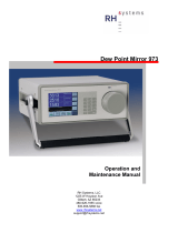
2.4 Water Reservoir
The HygroGen2 requires 50-80 ml of demineralised water in the internal reservoir.
Either reverse osmosis (RO) or de-ionised water is recommended. It is NOT recommended to
use distilled water as this readily absorbs atmospheric CO
2
to form carbonic acid which can
corrode components within the humidifier.
Insufficient water will deactivate the humidification system. As long as extreme care is taken
not to overfill the water reservoir, the HygroGen2 may be filled and emptied either with the
unit powered up or shut down.
i. To fill the HygroGen2:
a. Insert the tube of the dosing syringe, with the plunger fully depressed, 10 mm into the water
port and extract any residual water by drawing out the plunger.
b. Depress the collar on the water port (Figure 1(4) above) and remove the dosing syringe tube.
Wipe up any spilt water with an absorbent cloth immediately.
c. Fill the dosing syringe with 80 ml of demineralised water. Insert the end of the dosing syringe
tube firmly back into the water port and discharge the syringe steadily. (If water leaks during
this operation the filler tube is not correctly inserted in the water port.)
d. Depress the collar on the water port to remove the dosing syringe tube. Wipe up any spilt
water with an absorbent cloth immediately.
e. A water level indicator is shown in the Settings Screen (see section 3.4.5).
Caution: Do not overfill the HygroGen2
Overfilling of the unit will result in poor humidification and, in extreme cases, water may be
pumped into the chamber. If the HygroGen2 is overfilled, the humidifier should be fully
emptied and then refilled with 50-80 ml of water (as described above). If there is water present
in the chamber of the HygroGen2, this should be removed using an absorbent cloth. Ensure the
Figure 8: How to fill and empty the Water Reservoir

E-M-HG2-S-XL-V3.0
Rotronic AG
Bassersdorf, Switzerland
Document code
Unit
HygroGen2: Humidity and Temperature Generator
with AutoCal, MBW External Reference, Remote Screen
Share, RemoteAPI and Range Extension options.
Instruction Manual
Instruction Manual for Software
Version 3.0
Document Type
Page
18 of 102
Document title
© 2017; Rotronic AG E-M-HG2-S-XL-V3.0
HygroGen2 is switched off and the mains power unplugged before manually drying the
chamber.
ii. To empty the HygroGen2:
a. Insert the tube of the dosing syringe, with the plunger fully depressed, 10 mm into the water
port and extract any water by drawing out the plunger.
b. Depress the collar on the water port to remove the dosing syringe tube. Wipe up any spilt
water with an absorbent cloth immediately.
c. Water discharged from the HygroGen2 may be stored safely and reused at a later date.
Note: The HygroGen2 should always be emptied if it is being shipped or stored (see
section 5.3 Preparing the Unit for Transit or Storage). This will prevent ingress of water
into the chamber should the unit be inverted and prevent possible frost damage.
iii. Ultra-violet sterilisation lamp
As a precaution against any microbial and algae water contamination, HygroGen2 incorporates
an Ultra Violet (UV) sterilisation lamp within the water reservoir. No user intervention is
required - HygroGen2 auto-cycles the process.
Under no circumstance should the water reservoir be opened by non-qualified personnel.
Direct exposure to UV lamps can cause burns or blindness.

E-M-HG2-S-XL-V3.0
Rotronic AG
Bassersdorf, Switzerland
Document code
Unit
HygroGen2: Humidity and Temperature Generator
with AutoCal, MBW External Reference, Remote Screen
Share, RemoteAPI and Range Extension options.
Instruction Manual
Instruction Manual for Software
Version 3.0
Document Type
Page
19 of 102
Document title
© 2017; Rotronic AG E-M-HG2-S-XL-V3.0
3 HygroGen2 - Basic Operation
This applies to all HygroGen2 models. For details on the operation of optional Enhanced
Features, see section 4.
3.1 Switching On
a. Ensure the electrical mains supply is correctly plugged in and switched on.
b. Switch the unit on by pressing the Power Switch (see Figure 1(1) above) once.
c. The fans within the unit will switch on giving an immediate audible indication the unit is
powered.
d. The controller will power up and display the controller home screen (as shown in Figure 12).
On power up:
• The temperature and humidity set-points default to the last set values.
• The temperature and humidity control defaults to the last set condition.
If the “Low Water Level” alarm is displayed, then the unit should be filled as described in
section 2.4. Humidification is disabled until water is filled.
/