GNA
™
10 JOG LEVER ADAPTER
INSTALLATION
INSTRUCTIONS
Important Safety Information
WARNING
See the Important Safety and Product Information guide in the
product box for product warnings and other important
information.
You are responsible for the safe and prudent operation of your
vessel. The autopilot is a tool that enhances your capability to
operate your boat. It does not relieve you of the responsibility of
safely operating your boat. Avoid navigational hazards and
never leave the helm unattended.
Always be prepared to promptly regain manual control of your
boat.
Learn to operate the autopilot on calm and hazard-free open
water.
Use caution when operating the autopilot near hazards in the
water, such as docks, pilings, and other boats.
CAUTION
When in use, beware the risk of entrapment or pinching from
moving parts.
Failure to install and maintain this equipment in accordance with
these instructions could result in damage or injury.
NOTICE
To avoid damage to your boat, the autopilot system should be
installed by a qualified marine installer. Specific knowledge of
marine steering and electrical systems is required for proper
installation.
Tools and Supplies Needed
• Wire cutters/strippers
• Waterproof wire connectors (wire nuts) or heat-shrink tubing
and a heat gun
• Cable ties
• Jog lever or switch to connect to the system
Compatible and Recommended Jog Levers and Other
Devices
This device has been tested and confirmed to be compatible
with the jog lever models listed below, and complete wiring and
configuration details for these models are provided in these
instructions. Jog levers from other manufacturers may work with
this device when connected and configured using these
instructions, but compatibility cannot be guaranteed.
• Jastram
™
JO100-1 and JO300-1
• Kobelt
™
7170
• Simrad
™
S35
When selecting a switch to use with this device, consider these
guidelines.
• A single-pole, single-throw (SPST) switch, either latching or
momentary, can be used to trigger actions.
• A switch rated for IEC IP67 is recommended to best
withstand installation and use in a marine environment.
When selecting an indicator light to use with this device,
consider these guidelines.
• Although both incandescent and LED indicator lights are
compatible, an LED indicator is recommended because LED
indicator lights last longer and require less power to operate.
• The output signals from this device when using wiring
harness A as directed are regulated to 22 mA max. You can
use most LED indicator lights without installing a current
limiter.
• An indicator light rated for IEC IP67 is recommended to best
withstand installation and use in a marine environment.
Installing the Adapter
You can use this adapter to connect an external device to the
autopilot system, such as a jog lever, a normally open
momentary or latching switch, or an indicator light.
NOTE: You can install only one jog lever per GNA 10 adapter. If
you have multiple jog levers, you must install a separate adapter
for each jog lever.
1
Mount the external device according to the instructions
provided with the device.
2
Connect the bare wires from the external device to the GNA
10 adapter (Wiring Connections, page 1).
3
Repeat the previous two steps for additional external devices,
if necessary.
4
Connect the GNA 10 adapter to the same NMEA 2000
®
network as the autopilot system (NMEA 2000 Connection
Considerations, page 2).
5
Configure the behavior of the connected devices in the
software (Configuring the Adapter on a Chartplotter,
page 2).
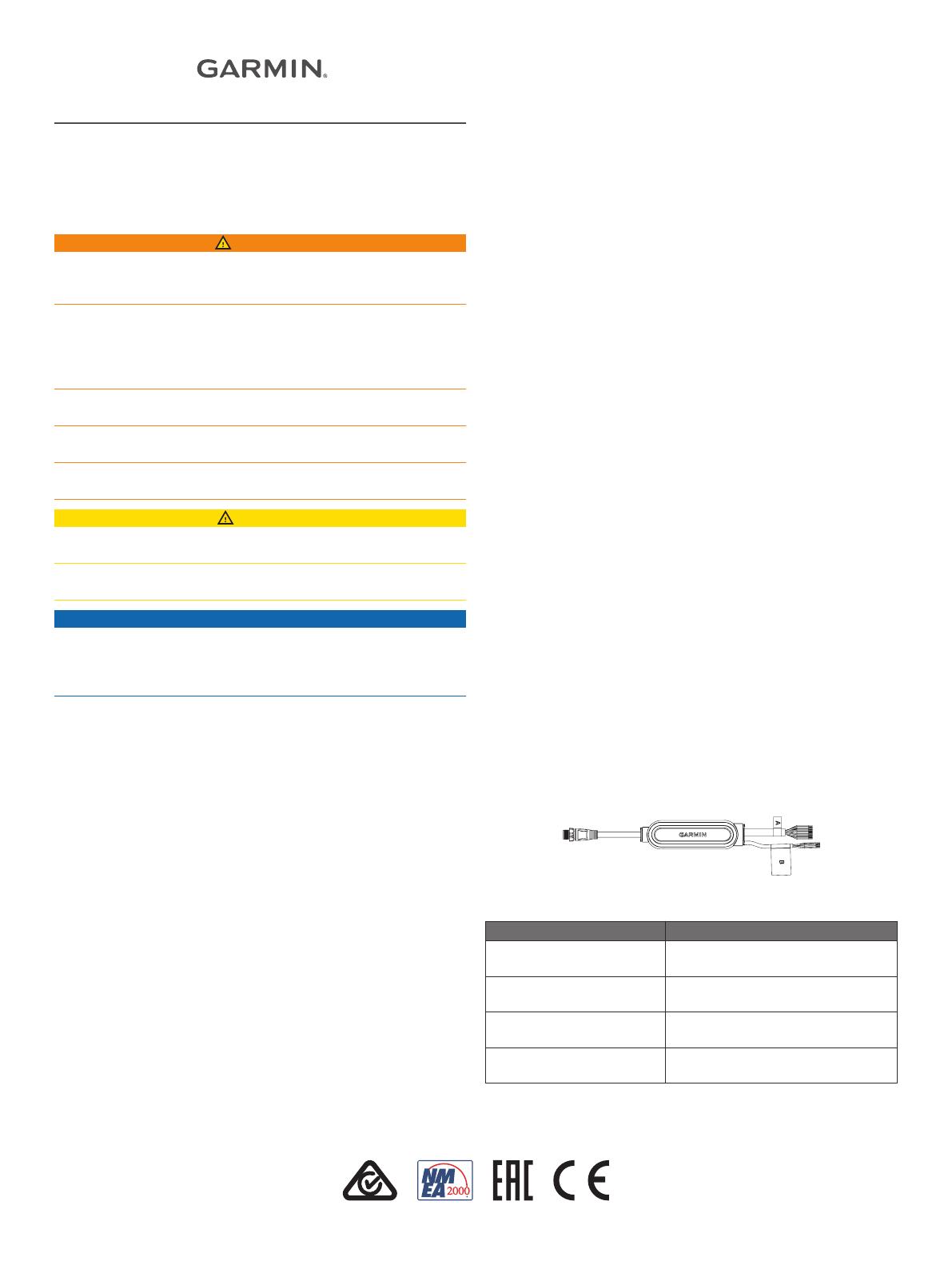
Wiring Connections
You should connect your device or devices using the harness
with the A label only. The harness with the B label is reserved
for future use.
The wires are organized in pairs, and each input and output
channel has both a positive (+) and negative (-) wire. You should
always connect your device using both wires in the pair.
If you need to extend these wires, you should use 24 AWG
(0.2 mm
2
) wire.
You should use solder and heat-shrink tubing when connecting
your device to these wires.
Wiring Harness A
Function Wire Colors
Input 1 Brown (+)
Black (-)
Input 2 Yellow (+)
Black (-)
Input 3 Blue (+)
Black (-)
Output 5 Green (+)
Violet (-)
GUID-0C1D7FD1-94FE-4820-A2B9-F4708CEEB67C v1December 2020


