
2000
Kickspace Heater Series
INSTALLATION
OPERATING
MAINTENANCE
QUIET-ONE
Models:
KS 2004, KS 2006
KS 2008, KS 2010
Please read these instructions thoroughly before beginning your installation!
Smith’s Quiet-One 2000 Series kickspace heaters are designed for installation in a forced hot water (hydronic) heating system. They may
also be used with conventional gas, oil, electric, or solar powered water heaters.
IMPORTANT: BEFORE INSTALLING ANY HEATING TERMINAL UNIT TO A DOMESTIC WATER
HEATER, CONSULT THE LOCAL PLUMBING CODES.
When installing a kickspace heater, an accurate heat loss calculation of the space is required. Match unit selection with BTUH output at
system water temperature and flow rate. See the capacity chart below for output at various water temperatures and flow rates.
NOTE: All kickspace heaters include a low limit aquastat which shuts off power to the fan when water temperature falls to 110
o
F. Power
is restored when water temperature rises to 130
o
F. When installing units with low temperature systems (radiant or water heater), it may
be necessary to change the aquastat to a special (90
o
/110
o
F) low temperature unit (part #S10046).
UNIT INSPECTION
Before starting the installation, carefully remove the kickspace heater from its box. Inspect for any damage caused in handling. The box
should include:
(1) Kickspace unit
(2) Molded grille endcaps (KS 2004 only)
(2) Mounting screws
(2) Screw covers
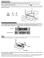
LOCATING THE KICKSPACE HEATER
Quiet-One 2000 Series kickspace units are designed for installation under kitchen cabinets, bathroom vanities, built-in shelves or benches,
and stairways. An available recessed wall mounting kit enables vertical installation with a flush mounted grille. Consideration should be
given in regards to perishable goods stored in the cabinet above the unit.
Environmental Products
Flow Rate
Pressure
GPM Drop (ft) 130 140 150 160 170 180 190 200 210
1 .06 2095 2410 2700 3000 3350 3650 3860 4000 4105
KS 2004 3 .422 2240 2650 3000 3350 3765 4350 4350 4530 4635
5 1.026 2350 2755 3140 3530 3940 4590 4590 4810 4935
1 .12 3410 4050 4655 5265 5860 6700 6700 7110 7270
KS 2006 3 1.19 3735 4395 5060 5735 6330 7120 7120 7530 7790
5 2.6 3860 4540 5225 5910 6560 7415 7415 7800 8010
1 .12 4300 5000 5765 6500 7370 8400 8400 8735 8920
KS 2008 3 1.19 4580 5380 6195 7050 7930 9010 9010 9445 9740
5 2.6 4760 5625 6450 7290 8200 9360 9360 9785 10020
1 .41 5530 6350 7150 7975 8780 9975 9975 10330 10520
KS 2010 3 2.78 5880 6710 7740 8710 9625 11060 11060 11530 11740
5 3.92 6070 7030 8000 9030 10025 11525 11525 11995 12180
Entering Water Temperature (in degrees F) - BTU/hrs.
Unit
•All capacities are rated by RTS with the kickspace installed under a cabinet and all capacities include the heat effect factor.
•For low speed ratings use: .85 for the KS2004, .75 for the KS2006, .70 for the KS2008 and .65 for the KS2010.
•Heat throw: KS2004 = 10’ @ 50 CFM; KS2006 = 10’ @ 75 CFM; KS2008 = 10’ at 90 CFM; KS2010 = 10’ @ 125 CFM.

PREPARING THE SITE
Once the location has been selected, it will be necessary to cut a 15” X 15” opening in the bottom shelf of the cupboard. This piece
should be saved for replacement after installation, and may be hinged to ease access to the unit.
NOTE: WHEN USING THE QUICK FIT HOSE KIT ACCESSORY ITEM, THIS STEP IS NOT REQUIRED. REFER TO
SEPARATE SHEET FOR INSTRUCTIONS.
The front kickboard must be cut to the A and B dimension listed for each unit. The box that your kickspace heater came in has a handy
template to ensure accurate cuts. Holes must be drilled in the floor or back wall of the cabinet to allow for supply and return piping (1/2”)
and electrical connection.
A B
KS 2004 14” 3 1/2”
KS 2006 18 1/2” 3 1/2”
KS 2008 18 1/2” 3 1/2”
KS 2010 22 1/8” 3 13/16”
INSTALLING THE KICKSPACE HEATER
Place the molded grille endcaps on either side of the grille (KS 2004 only). Slide the kickspace unit backwards into the opening in the
kickboard until the endcaps and grille are flush with the finished surface of the kickboard. Secure the unit with screws provided through
holes in the endcaps (or grille), and place screw covers over the screws. Check to ensure that unit is both secure and level.
NOTE: UNLIKE COMPETITIVE MODELS, IT IS NOT NECESSARY TO SCREW THE QUIET-ONE UNITS TO THE FLOOR.
KS 2004
KS 2006, 2008, 2010
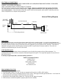
PIPING
Water supply and return connections are 1/2” copper tube. The water supply is the bottom tube and must be soldered first. After
soldering the return connection (top tube), check that both connections are leak free.
NOTE: ISOLATION VALVES ARE RECOMMENDED ON BOTH SUPPLY AND RETURN PIPING TO ALLOW FOR SERVICE
AND BALANCING IF NECESSARY.
When filling the kickspace unit with system water, it will be necessary to remove the air from it. A built in bleeder air vent is accessible
through the front of the unit by removing the rubber grommet. This vent may be operated with a screwdriver through the grille. Be
careful as some water may be bled along with air. See diagrams for recommended piping arrangements.

Piping Diagrams
Two Pipe
Reverse Return
One Pipe Series Loop
(Note: Monoflofittings
may be required)
Water Heater
As A Source

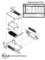
Replacement Parts
Part Description Replacement Part Number
KS 2004 KS2006 KS 2008 KS 2010
1 Coil S10007 S10123 S10123 S10126
2 + Grille S10008 S10130 S10130 S10131
3 * Fan motor S10009 S10124 S10125 S10127
4 * Outboard bearing S10010 S10010 S10010 S10010
5 * Blower wheel S10011 S10011 S10011 S10128
6** Aquastat S10012 S10012 S10012 S10012
7 Rocker switch S10013 S10013 S10013 S10013
+ Grille parts for the KS 2004 are the end caps only.
* Available as a complete unit (KS 2004-10229; KS 2006-10230; KS 2008-10231;
KS 2010-10232).
** Available as a kit (Part #S10028 - 110
o
F-130
o
F)
(Part #S10046 - 90
o
F -110
o
F)
Environmental Products

OPERATION
Before replacing the access cover in the cabinet bottom, ensure that the unit is operating properly. Activate the system thermostat and
place speed switch on the front of the kickspace unit on MIN. Because of the low limit aquastat, it may take several minutes before the fan
is activated. When the fan does come on, ensure that the switchis operational by moving position to OFF, then MAX. Best results are
obtained by leaving the switch in the MIN position and reserving MAX for quick heat up or extreme conditions. If the unit is not
operating, see troubleshooting tips at the end of this manual.
UNIT MAINTENANCE
The Quiet-One 2000 Series kickspace heaters are designed for years of trouble free operation with very little maintenance. It is
recommended however that the unit be vacuumed occasionally through the front grille. This is especially important in areas with lots of
dust, pet hair and dirt.
If servicing is required beyond this, contact the installing contractor or
Smith’s Environmental Products
Customer Service
1875 Dewey Ave.
Benton Harbor, MI 49023
(269) 925-8818
www.smiths-env.com
TROUBLESHOOTING TIPS
If the kickspace heater fan does not operate:
1. Verify that supply voltage is 120 VAC, all wires are connected, and fan switch is in MIN or MAX position.
2. Verify that hot water is going to and through the unit at 130
o
F or above. Both supply and return pipes should be hot. An air bound coil
will prevent the fan from operating. Bleed air from the coil if necessary.
3. By pass the low limit aquastat using a jumper wire. If the fan now runs, replace the aquastat.
4. If the fan does not run while the aquastat is jumped, replace the motor assembly.
ELECTRICAL CONNECTIONS
ALL ELECTRICAL CONNECTIONS MUST COMPLY WITH LOCAL AND/OR NATIONAL REGULATIONS. IF IN DOUBT,
CONSULT A QUALIFIED ELECTRICIAN.
Smith’s Environmental Products’ kickspace heaters are UL approved.
Remove the electrical junction box cover through the screw provided. There are two knockouts in the back and side of the junction
box. Select the most convenient and bring wiring through it. Supply conductors should be 14 AWG and protected by a 15 AMP
over current protector. Connect line input to black lead, neutral to white lead, and ground to pillar marked G inside the junction box.
Refer to diagram below for complete wiring instructions.
120V-60HZ
ph A.C. supply
Ground
Pillar
G
white
white
low limit thermostat
black
Field wiring enclosure
yellow
control switch
boost
normal
off
red
fan motor
Internal Wiring Diagram
-
 1
1
-
 2
2
-
 3
3
-
 4
4
-
 5
5


Vent-Rite Valve KS 2006 Installation guide
- Type
- Installation guide
Ask a question and I''ll find the answer in the document
Finding information in a document is now easier with AI
Other documents
-
 Quiet-One KS2010 User guide
-
 Quiet-One KS2006 Specification
-
 Myson Kickspace 500 Installation, Operating, Maintenance And After Sales Manual
-
 EverCool HPFA-10025EA BUFFALO Datasheet
-
Myson Kickspace 800 User manual
-
-
 ITT-Bell & Gossett 108119 Installation guide
-
 Myson Kickspace 500 Owner's manual
-
Myson Kickspace 600 User manual
-


