Mutec MC-1.1+ AES Splitter-Konverter User manual
- Category
- Video line amplifiers
- Type
- User manual
This manual is also suitable for

AES3 – AES3id – S/P-DIF
DIGITAL AUDIO FORMAT CONVERTER


WARRANTY REGULATIONS
§1 Warranty
MUTEC GmbH warrants the flawless performance of this product to the original buyer for a period of two (2) years from the date of purchase. If any failure occurs within
the specified warranty period that is caused by defects in material and/or workmanship, MUTEC GmbH shall either repair or replace the product free of charge within 90
days. The purchaser is not entitled to claim an inspection of the device free of charge during the warranty period. If the warranty claim proves to be justified, the product
will be returned freight prepaid by MUTEC GmbH within Germany. Outside Germany, the product will be returned with the additional international freight charges payable
by the customer. Warranty claims other than those indicated above are expressly excluded.
§2 Warranty transferability
This warranty is extended exclusively to the original buyer who bought the product from a MUTEC GmbH specialized dealer or distributor, and is not transferable to anyone
who may subsequently purchase this product. No other person (retail dealer, distributor, etc.) shall be entitled to give any warranty promise on behalf of MUTEC GmbH.
§3 Waranty regulations
The return of the completed registration card, or online registration on one of the websites specified below, is a condition of warranty. Failing to register the device before
returning it for repair will void the extended warranty.
The serial number on the returned device must match the one stated on the registration card or entered during online registration. Otherwise, the device will be
returned to the sender at the sender’s expense.
Any returned device must be accompanied by a detailed error description and a copy of the original sales receipt issued by a MUTEC dealer or distributor.
The device must be returned free of shipping expenses and in the original package, if possible; otherwise, the sender has to provide comparably protective packaging.
The sender is fully responsible for any damage or loss of the product when shipping it to MUTEC GmbH.
§4 Limitation of warranty
Damages caused by the following conditions are not covered by this warranty:
Damages caused by every kind of normal wear and tear (e.g. displays, LEDs, potentiometers, faders, switches, buttons, connecting elements, printed labels, cover
glasses, cover prints, and similar parts).
Functional failure of the product caused by improper installation (please observe CMOS components handling instructions!), neglect or misuse of
the product, e.g. failure to operate the unit in compliance with the instructions given in the user or service manuals.
Damage caused by any form of external mechanical impact or modification.
Damage caused by the user’s failure to connect and operate the unit in compliance with local safety regulations.
Damage caused by force majeure (fire, explosion, flood, lightning, war, vandalism, etc.).
Consequential damages or defects in products from other manufacturers as well as any costs resulting from a loss of production.
Repairs carried out by personnel which is not authorized from MUTEC GmbH will void the warranty.
Adaptations and modifications to the device made with regard to
national, technical, or safety regulations in a country or of the customer do not constitute a warranty claim and should be set with MUTEC GmbH in advance.
§5 Repairs
To obtain warranty service, the buyer must call or write to MUTEC GmbH before returning the unit. All inquiries must be accompanied by a description of the problem and
the original buyer’s invoice. Devices shipped to MUTEC GmbH for repair without prior notice will be returned to the sender at the sender’s expense.
In case of a functional
failure please contact:
MUTEC Gesellschaft fuer Systementwicklung und Komponentenvertrieb mbH
Siekeweg 6/8 • 12309 Berlin • Germany • Fon 030-746880-0 • Fax 030-746880-99 • Tecsuppor[email protected] • www.MUTEC-net.de
MUTEC GmbH assumes no liability for any incorrect information given in this manual. Please note that
all software/hardware product names are registered trademarks of their respective owners. No part of
this manual may be reproduced, copied or converted to a machine-readable form or electronical media
without a written permission of MUTEC GmbH. We reserve the right to change or improve our products
without notice.
©
MUTEC GmbH 2012
SAFETY INSTRUCTIONS
General instructions
To reduce the risk of fire or electrical shock, do not expose this appliance to rain or moisture, direct
sunlight or excessive heat from sources such as radiators or spotlights. No user serviceable parts are in-
side. Repair and maintenance must be carried out by qualified personnel authorized by MUTEC GmbH!
The unit has been designed for operation in a standard domestic environment. Do NOT expose the unit
and its accessories to rain, moisture, direct sunlight or excessive heat produced by such heat sources as
radiators or spotlights! The free flow of air inside and around the unit must always be ensured.
Initial operation
Prior to the initial operation of the unit, the appliance, its accessories and packaging must be
inspected for any signs of physical damage that may have occurred during transit. If the unit has
been damaged mechanically or if liquids have been spilled inside the enclosure, the appliance may
not be connected to the mains or must be disconnected from the mains immediately! If the unit is
damaged, please do NOT return it to MUTEC GmbH, but notify your dealer and the shipping com
-
pany immediately, otherwise claims for damage or replacement may not be granted.
If the device is left in a low-temperature environment for a long time and then is moved to a room-
temperature environment, condensation may occur on the inside and the exterior. To avoid short-
circuits and flashovers, be sure to wait one or two hours before putting the device into operation.
Power supply
The device contains a self-adapting wide-range power supply supporting the majority of global stan-
dard line voltages within a range of 90…250 V, with no need for making adjustments. Make sure that
your line-voltage source provides a supply voltage within the specified range. In addition, make sure
that the device is properly grounded via the local electric installation.
Please use the enclosed power cord (see packaging) to connect the unit to the mains. Switch the
unit off before you attempt to connect it to the mains. Connect the power cord to the unit, then
to a standard 3-pin mains outlet. To draw the power cord, never pull on the cable but on the mains
plug!
The unit must be grounded during operation!
For information on the power-inlet wiring, refer to the »Wiring of connectors« section in the
appendix. Disconnect the device from the mains when not using it for an extended period!
This symbol, an exclamation mark inside a triangle,
alerts you to important operating or safety instructions
in this manual.
This symbol, a flash of lightning inside a triangle, alerts
you to the presence of uninsulated dangerous voltage
inside the enclosure - voltage that may be sufficient to
constitute a risk of shock.
Declaration of Conformity
We herewith confirm that the product complies with the European
Commission’s standards on electromagnetic compatibility.
Interference emission: EN 50081-1, 1992
Resistance to interference: EN 50082-1, 1992
Presupposed as operation condition is that all clock outputs are con-
nected with high-quality and good shielded BNC 75 ohms cable.
!
R I S K O F
ELECTRICAL SHOCK!
C A U T I O N
!


CONTENT
INTRODUCTION
General Function Description . . . . . . . . . . . . . . . . . 7
Features . . . . . . . . . . . . . . . . . . . . . . . . . . . . .
7
Applications . . . . . . . . . . . . . . . . . . . . . . . . . . . 7
Peripheral MUTEC Products
. . . . . . . . . . . . . . . . . . 8
CONTROL ELEMENTS AND TERMINALS
MC-1.1+ Front Panel . . . . . . . . . . . . . . . . . . . . . . 9
MC-1.1+ Rear Panel . . . . . . . . . . . . . . . . . . . . . . . 9
INSTALLATION
Content of the Box . . . . . . . . . . . . . . . . . . . . . . . 11
Placing the device . . . . . . . . . . . . . . . . . . . . . . . 11
Wiring the AES/EBU, AES/EBUid and S/P-DIF Interfaces . . . 11
OPERATION
Selecting Function Menus and setting Functions . . . . . . 13
Steps of Operation . . . . . . . . . . . . . . . . . . . . . . . 13
OPERATING THE MC-6
MODE + AUDIO IN
+
SCMS Menus . . . . . . . . . . . . . . . 15
General Operation Procedure
. . . . . . . . . . . . . . . . . 15
Unidirectional Format Conversions . . . . . . . . . . . . . . 16
Unidirectional Format and Sampling Rate Conversions
. . . 16
Signal Splitting Mode . . . . . . . . . . . . . . . . . . . . . 17
SCMS Functions . . . . . . . . . . . . . . . . . . . . . . . . . 18
STATUS Area
. . . . . . . . . . . . . . . . . . . . . . . . . . 18
APPENDIX
Pin Assignment of the Connectors . . . . . . . . . . . . . . 19
Technical Data . . . . . . . . . . . . . . . . . . . . . . . . . 20


> > > > > > > > > > > > > > > > > > > > > > > > > > > > > > > > > > > > > > > > > > > > > > > > > > > > > > > > > > > > > > > > > > > >
88
\
B E D I E N E L E M E N T E
B E D I E N E L E M E N T E
B E D I E N E L E M E N T E
> > > > > > > > > > > > > > > > > > > > > > > > > > > > > > > > > > > > > > > > > > > > > > > > > > > > > > > > > > > > > > > > > > > >
Manual SDs-01 D 3.2.2003 17:45 Uhr Seite 3
INTRODUCTION
Thank you very much for purchasing the MC-1.1+, Digital Audio Format
Converter, from MUTEC!
General Function Description
The MC-1.1+ is a multifunctional, high-performance digital audio format
converter for AES3, AES3id and S/P-DIF. Using latest digital audio circuit-
ries and low-jitter PLLs, the MC-1.1+ enables to improve and re-stabilize
incoming digital audio signals, while converting and splitting those to the
corresponding outputs. all audio formats can be processed up to 192.0kHz.
The MC-1.1+ helps you to interconnect devices which use different digital
audio formats and incompatible interfaces. The format conversion process
does not only the necessary electrical conversion but also a format conversi-
on of the reference signals in compliance with the specifications which are
standardized by the Audio Engineering Society (AES) and the International
Electrotechnical Commision (IEC).
Dual low-jitter PLL circuitries allow to run two signal paths independently for
realtime bidirectional format conversions. Additionally, the MC-1.1+ provides
two outputs for each digital audio format which enables the use as signal
splitter or
distribution amplifier.
Various uni- and bidirectional operation modes
, 4-way signal splitting,
SCMS processing or signal status detection make the use of the MC-1.1+
possible in a wide range of applications.
Features
AES/EBU3, AES3/EBUid and S/P-DIF optical/coaxial interfaces in one box.
Uni- and bidirectional format conversions from 32.0kHz to 192.0kHz bet-
ween AES3/11 and S/P-DIF.
Simultaneous format conversion to all output formats while allowing
the original signal to pass through.
Signal improvement by low-jitter audio PLLs.
AES3/11, AES3id/11id and S/P-DIF optical/coaxial signal splitting.
SCMS processing and status analyzing.
NONE-PCM and DTS bitstream detections.
Easy configurable.
User‘s settings will be stored after switching-off.
Rack space saving 1/2 19“ case allows for mounting two devices in one
rack unit.
Built-in international power supply.
Applications
Interconnection of consumer and professional digital audio devices.
Realtime bi-directional signal transfer and format conversion between
send/returns of digital mixing consoles and effect processors.
Uni- or bi-directional interconnection of computer-based sound cards
with professional digital audio equipment.
AES3/AES11 and S/P-DIF signal splitting and distribution.
Digital audio signal refreshing.
SCMS coding of digial audio productions to protect those against illegal
copying.
S/P-DIF optical/coaxial status analyzing.
7
Boxes which contain a triangle with
an exclamation mark inside should
be read carefully!
These include
additional information which are of major
importance for the functional descriptions
in the text column.
!
The grey boxes contain supplementary
informationen for the corresponding
sections in the text columns. The content of
the individual box refers to the description
in the text column beside the box.
Register your MUTEC Product
for Warranty and Support!
We ask you to be so kind to register
your MUTEC product through our website
immediately after purchasing. This ensures
full warranty services over a period of two
years after purchasing the product. More-
over, for all registered products we offer to
our customers technical support. We also
will inform you about product updates and
new products which may of interest for you
(on voluntary base, of course).
Please regsiter your product at:
www.MUTEC-net.
com
> SERVICES, > MUTEC Product Registration
!

\\\\\\\\\\\\
I N T R O D U C T I O N
I N T R O D U C T I O N
I N T R O D U C T I O N
> > > > > > > > > > > > > > > > > > > > > > > > > > > > > > > > > > > > > > > > > > > > > > > > > > > > > > > > > > > > > > > > > > > >
> > > > > > > > > > > > > > > > > > > > > > > > > > > > > > > > > > > > > > > > > > > > > > > > > > > > > > > > > > > > > > > > > > > >
88
Manual SDs-01 E 3.2.2003 18:26 Uhr Seite 5
8
Peripheral MUTEC Products
Format and Sampling Rate Converters with internal Master Clock:
MC-4
The MC-4 is a high-performance digital audio multichannel format and
sampling rate converter for ADAT
TM
, AES3 and S/P-DIF
MC-6
The MC-6 is a high-performance digital audio dual channel format con-
verter for AES3, AES3id and S/P-DIF.
MC-8 + MC-8.1
The MC-8 and MC-8.1 are 8 channel, high-performance digital audio and
sampling rate converters for AES3 and AES3id.
Digital Signal Distribution Amplifier:
MC-2
The MC-2 is a high-performance digital audio and reference sync signal
distribution amplifier for AES3/11 and AES3/11id signals. The unit distrib-
ute s and converts between the mentioned AES signals and standards.
Accessories for the MUTEC MC Product Series:
Optical cables in different lenghts from 0.5 m to 20 m for S/P-DIF and
ADAT
TM
transfers.
MW-02/19
Mounting plate to install two MC products side by side into one unit of
a 19” rack.
MW-03/19
Set of two rack mounting angles to install one MC product on the rear
side of a 19” rack.
MW-05/19
Set of two rack mounting angles to install one MC product frontally into
one unit of a 19” rack.
For all peripheral products please have a look on our website:
www.MUTEC-net.com

> > > > > > > > > > > > > > > > > > > > > > > > > > > > > > > > > > > > > > > > > > > > > > > > > > > > > > > > > > > > > > > > > > > >
88
\
B E D I E N E L E M E N T E
B E D I E N E L E M E N T E
B E D I E N E L E M E N T E
> > > > > > > > > > > > > > > > > > > > > > > > > > > > > > > > > > > > > > > > > > > > > > > > > > > > > > > > > > > > > > > > > > > >
Manual SDs-01 D 3.2.2003 17:45 Uhr Seite 3
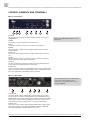
CONTROL ELEMENTS AND TERMINALS
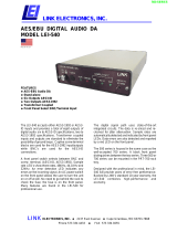
MC-1.1+ Front Panel
1 POWER
This red LED lights up when the unit is switched on with the rear panel
POWER switch.
2 SELECT
Use this key to access the different functional menus.
3 DATA
Use this key to select a function from a specific functional menu.
4 MODE
This function menu allows to select all digital audio format conversion
modes available.
5 AUDIO IN
This function menu allows to select the digital audio formats for conver-
sion.
6 SCMS
This function menu offers three different ways to encode the outgoing
S/P-DIF optical and coaxial digital audio signals.
7 STATUS
This menu indicates various signal statuses of incoming S/P-DIF optical or
coaxial digial audio signals by means of status LEDs.
8 AES3id OUT
These two outputs transmit two AES3id digital audio stereo or blank frame
signals in compliance with the AES3id–2001 or AES 11–1997/2003 standards.
The output impedance is 75 Ω (BNC connectors, female).
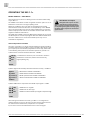
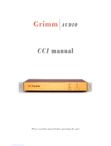
MC-1.1+ Rear Panel
1 S/P-DIF OUT
These four S/P-DIF outputs, available as 2 x optical (»OP«) and 2 x coaxial
(»CO«) interfaces, transmit an optical S/P-DIF and an unbalanced electrical
S/P-DIF digital audio or blank frame signal in compliance with the IEC 60958
standard. The coaxial interface impedance is 75 Ω. (cinch connector), the
optical interface offers a Toshiba Toslink
TM
connector, EIAJ standard.
2 AES3/11 OUT
These two outputs transmit a balanced digital AES3 audio or AES11 blank
frame signal compliant with AES 3–1992 (R1997) and AES 11–1997/2003.
The output impedance is 110 Ω (XLR connectors, male).
9
MC-1.1 Rear Panel
MC-1.1+ Front Panel
Refer to the OPERATIONS chapter for more
information.
For detailed specifications on all terminals,
refer to the »Pin Assignment of the
Connectors« and »Technical Data« in the
chapter APPENDIX.
4
3
2
1
1
2
3
4
5
6
5
6
7
8

\\\\\\\\\\\\\
C O N T R O L E L E M E N T S
C O N T R O L E L E M E N T S
C O N T R O L E L E M E N T S
> > > > > > > > > > > > > > > > > > > > > > > > > > > > > > > > > > > > > > > > > > > > > > > > > > > > > > > > > > > > > > > > > > > >
> > > > > > > > > > > > > > > > > > > > > > > > > > > > > > > > > > > > > > > > > > > > > > > > > > > > > > > > > > > > > > > > > > > >
88
Manual SDs-01 E 3.2.2003 18:26 Uhr Seite 6
3 AES/EBU IN
This input receives a balanced AES3 digital audio or AES11 blank frame
signal compliant with AES 3–1992 (R1997) and AES 11–1997/2003. The input
impedance is 110 Ω (XLR connector, female).
4 S/P-DIF IN
These two S/P-DIF inputs, available as optical (»OP«) and coaxial (»CO«)
interfaces, can receive an optical S/P-DIF and an unbalanced electrical S/P-DIF
digital audio or blank frame signal in compliance with the IEC 60958 stand-
ard. The coaxial interface impedance is 75 Ω. (cinch connector), the optical
interface offers a Toshiba Toslink
TM
connector, EIAJ standard.
5 AES3id IN
This receives an AES3id digital audio or AES11id blank frame signal in com-
pliance with the AES3id–2001 standard. The impedance of both connector
is 75 Ω (BNC connectors, female).
6 MAINS IN, Power Switch + Power Inlet
This is the main switch for switching the device on and off. Be sure to
make all connections (especially the supplied power cable) properly before
turning on the switch. Heed the SAFETY INSTRUCTIONS at the beginning of
this manual.
Connect the supplied power cable here. Make sure that the power switch
is turned off before connecting the power cable to this inlet and to the
power outlet. Line voltages within the range of 90…260 V with a frequency
of 50 or 60 Hz can be applied. The internal power supply will automatically
make all necessary adjustments.
10

> > > > > > > > > > > > > > > > > > > > > > > > > > > > > > > > > > > > > > > > > > > > > > > > > > > > > > > > > > > > > > > > > > > >
88
\
B E D I E N E L E M E N T E
B E D I E N E L E M E N T E
B E D I E N E L E M E N T E
> > > > > > > > > > > > > > > > > > > > > > > > > > > > > > > > > > > > > > > > > > > > > > > > > > > > > > > > > > > > > > > > > > > >
Manual SDs-01 D 3.2.2003 17:45 Uhr Seite 3
11
INSTALLATION
Content of the Box
The unit was packed carefully. Nevertheless we recommend to check the
content directly after opening the package:
1 x MC-1.1+
1 x Power cable
4 x Rubber feet
1 x Manual
Placing the Device
The unit should be set up as closely as possible to the devices to which it
will be connected, so as to avoid excessive cable lengths. Use the 4 rubber
feets enclosed with the appliance and stick them symmetrically on the
bottom side of the unit to protect the enclosure and supporting surface
from being damaged.
The device can be mounted into a standard 19“ rack and will require 1 unit.
In this case, the rubber feet cannot be attached. Install the device so that
one unit of rack space is left free both above and below the device to allow
for sufficient ventilation! The mounting depth including the terminals is
160 mm/6.7“. Another 60 mm/2.4“ should be added for the required cables.
Additional slide-in rails on the rack inside are recommended for safe instal-
lation. This will also avoid long-term mechanical deformation of the housing.
Wiring the AES/EBU and S/P-DIF Interfaces
Connect the AES/EBU interfaces with the help of balanced electrical
cables equipped with XLR connectors on both ends. The specifications
stipulate a specific cable resistance of 110
Ω (ask your retailer for a confir-
mation of this value when purchasing the cables).
Connect the coaxial S/P-DIF interface with the help of unbalanced electri
-
cal cables equipped with cinch connectors on both ends. The specifications
stipulate a specific cable resistance of 75
Ω (ask your retailer for a confirma-
tion of this value when purchasing the cables).
Since some manufacturers offer optimized
cables for the transmission of digital S/P-DIF
and AES3/11 signals, it is a good idea to ask
your retailer for specific cables.
Before installing the unit the section
SAFETY INSTRUCTIONS located
at the beginning of this manual
should be read carefully.
!
The condition of the packaging material
and the device should be checked carefully
additionally. If there are any damages
please refer to SAFETY INSTRUCTIONS,
Initial Operation, and WARRANTY
REGULATIONS.
Never expose the device and
accessories to rain, moisture,
direct sunlight, or excessive heat
produced by radiators, heaters, or spot
lights! Sufficient air circulation in the
environment of the device must be ensured!
!
Especially when working with high
AES3/11 clock rates well shielded
clock lines are imperative to avoid
increased radiation! Standard cables are nor-
mally useable for clock rates up to 50.0kHz.
Special shielded cable material should be
used for transfer of higher clock rates.
!

12

> > > > > > > > > > > > > > > > > > > > > > > > > > > > > > > > > > > > > > > > > > > > > > > > > > > > > > > > > > > > > > > > > > > >
88
\
B E D I E N E L E M E N T E
B E D I E N E L E M E N T E
B E D I E N E L E M E N T E
> > > > > > > > > > > > > > > > > > > > > > > > > > > > > > > > > > > > > > > > > > > > > > > > > > > > > > > > > > > > > > > > > > > >
Manual SDs-01 D 3.2.2003 17:45 Uhr Seite 3
13
OPERATION
Selecting Function Menus and setting Functions
The device is fully operated using the two toggle switches at the front
panel.
1 Switching the MENU key toggles between different basic function menus.
2 Switching the SELECT key activtes individual functions within one
function menu.
Steps of Operation
1 First press on »MENU« or »SELECT« key enables the last selected function
within the last selected function menu. The corresponding LED is
beginning to flash.
2 Every press on »SELECT« button will select a new function within a menu.
The LED of the selected function flashs accordingly. After the LED stops
flashing, the funcltion is activated.
3 When the needed function is selected, do not press the switches again!
After a period of approx. 4 seconds the LED of the selected function stops
flashing.
The STATUS area is not accessible by using the »MENU« and »SELECT« keys,
because it only informs about different conditions of incoming signals.
Safety Instructions
For safety reasons, be sure to
read the SAFETY INSTRUCTIONS
and INSTALLATION chapters before first
powering-up!
We also recommend reading the CONTROL
ELEMENTS AND TERMINALS chapter for
information on how to connect MC-1.1+ !
!
User Settings Remain
All user-specific function settings
are available furthermore when
power is restored.
!
Shut-Down of Outputs
All digital audio outputs are shut-
down during function selection!
After a function is finally selected and the
corresponding LED lights constantly again,
the digital audio outputs are activated for
signal transfer.
!
Functions
Menus
Menus
Functions
2. SELECT
selects individual
functions within
one function
menu.
1. MENU
selects individual
function menus.
MENU + SELECT operation


> > > > > > > > > > > > > > > > > > > > > > > > > > > > > > > > > > > > > > > > > > > > > > > > > > > > > > > > > > > > > > > > > > > >
88
\
B E D I E N E L E M E N T E
B E D I E N E L E M E N T E
B E D I E N E L E M E N T E
> > > > > > > > > > > > > > > > > > > > > > > > > > > > > > > > > > > > > > > > > > > > > > > > > > > > > > > > > > > > > > > > > > > >
Manual SDs-01 D 3.2.2003 17:45 Uhr Seite 3
15
OPERATING THE MC-1.1+
MODE + AUDIO IN
+
SCMS Menus
These three function menus are offering access to the whole functionality
of your MC-1.1+.
The »MODE« menu allows to select the general conversion option as uni- or
bidirectional conversion or the signal splitting mode.
Within the »AUDIO IN« menu you select for the digital audio formats
which should be converted. This menu acts in dependency of the »MODE«
menu. The system makes sure that only useful combinations of conversion
modes and proper audio formats are accessable. Therefore both menus act
together in different combinations.
The SCMS« menu (SCMS = Serial Copy Management System) let you encode
the S/P-DIF optical + coaxial output signals with three different SCMS status.
The menu »STATUS« is for control of the S/P-DIF inputs only. It is not
accessable for adjustments.
General Operation Procedure
The menu of your MC-1.1+ is strictly organized aligned to general handling
procedures when inserting the MC-1.1+ into your studio‘s data stream. Thus,
you can split up all of the necessary adjustments in three steps, which leads
to the following three questions for the basic operation of your MC-1.1+:
1) What kind of conversion should be executed → MODE?
2) Which digital audio format(s) should be involved as source(s) → AUDIO
IN?
3) Which SCMS status is required for the S/P-DIF output signals → SCMS?
After these general decisions are made, your MC-1.1+ is configured for
optimal operation in your set-up! Due to the fact that the system monitors
for useful function combinations, maloperation is not possible.
So, let‘s have a look to the individual functions on the next pages.
BI-DIR = Bidirectional conversion, between two formats only
UNI-DIR = Unidirectional conversion, from one format to all others
SPLIT = Signal splitting only
MODE
AES3 = AES3 between 25.0kHz and 200.0kHz
S/P-DIF op
1
= S/P-DIF optical between 25.0kHz and 200.0kHz
AES3id = AES3id between 25.0kHz and 200.0kHz
S/P-DIF co
2
= S/P-DIF coaxial between 25.0kHz and 200.0kHz
AUDIO IN
Shut-Down of Outputs
All digital audio outputs are shut-
down during function selection!
After a function is finally selected and the
corresponding LED lights constantly again,
the digital audio outputs are activated for
signal transfer.
!
ORIG = SCMS status as »original«
PASS =
SCMS status of the S/P-DIF input signal is looped through
1st = SCMS status as »first copy«
SCMS
1 2

\\\\\\\\\\\\
O P E R AT I O N
O P E R AT I O N
O P E R AT I O N
> > > > > > > > > > > > > > > > > > > > > > > > > > > > > > > > > > > > > > > > > > > > > > > > > > > > > > > > > > > > > > > > > > > >
> > > > > > > > > > > > > > > > > > > > > > > > > > > > > > > > > > > > > > > > > > > > > > > > > > > > > > > > > > > > > > > > > > > >
88
Manual SDs-01 E 3.2.2003 18:26 Uhr Seite 12
16
BI-DIR
UNI-DIR AES3
S/P-DIF op
1
SPLIT
This setting allows for unidirectional format conversion (see »MODE«, »UNI-
DIR«) of an AES3 source signal (see »AUDIO IN«, »AES3«) simultaneously to
all available output formats. The SCMS status of the S/P-DIF output signals
is set to original (see »SCMS -1«, »ORIG«). Thus, the original input signal is
not lost during the conversion process and available for further use!
Within the »AUDIO IN« menu, you can select with the »SELECT« button the
other available digital audio inputs. When selecting one of the S/P-DIF in-
puts, the SCMS status of the input signal will be displayed in the »STATUS«
area with the first (»1«) row of LEDs.
To set the SCMS status of the S/P-DIF outputs as »ORIG« or »1st«, enter the
SCMS« menu by pressing the »MENU« button repeatedly and select with
the »SELECT« button the option prefered. The SCMS settings are made in-
dependently of the SCMS status of the incoming S/P-DIF signal. If you want
to have the SCMS status of the S/P-DIF outputs equal to this one of the S/P-
DIF input signal, select »PASS«.
Further Setting Examples
SCMS
DTS-CD
NONE-PCM
1st
ORIG
MODE
AES3id
S/P-DIF co
2
AUDIO IN
ORIG
PASS
1st
Unidirectional Format Conversions
Unidirectional format conversion from AES3id to AES3, S/P-DIF optical + coaxial,
AES3id. The SCMS status of the S/P-DIF outputs is set as first copy.
1 2
1 2
STATUS
BI-DIR
UNI-DIR AES3
S/P-DIF op
1
SPLIT
SCMS
DTS-CD
NONE-PCM
1st
ORIG
MODE
AES3id
S/P-DIF co
2
AUDIO IN
ORIG
PASS
1st
1 2
1 2
STATUS
Unidirectional format conversion from S/P-DIF coaxial to AES3, AES3id, S/P-DIF
optical + coaxial. The SCMS status of the S/P-DIF outputs is set as first copy. The
SCMS status of the S/P-DIF input signal is original.
BI-DIR
UNI-DIR AES3
S/P-DIF op
1
SPLIT
SCMS
DTS-CD
NONE-PCM
1st
ORIG
MODE
AES3id
S/P-DIF co
2
AUDIO IN
ORIG
PASS
1st
1 2 1 2
STATUS
Bidirectional Format Conversions
BI-DIR
UNI-DIR AES3
S/P-DIF op
1
SPLIT
SCMS
DTS-CD
NONE-PCM
1st
ORIG
MODE
AES3id
S/P-DIF co
2
AUDIO IN
ORIG
PASS
1st
1 2
1 2
STATUS
This is a special function of your MC-1.1+! It allows, as shown in the sketch
above, to receive an AES3 and AES3id signal simultaneously. The AES3 input
signal is converted to AES3id and the AES3id input signal is converted to
AES3. The other digital audio outputs are shut down. In this mode, the MC-
1.1+ is able to work simultaneously with two different sampling rates.
Any combination of two inputs for bidirectional conversion is possible to
select by pressing the »SELECT« button repeatedly within the »AUDIO IN«
menu.

\\\\\\\\\\\\
O P E R AT I O N
O P E R AT I O N
O P E R AT I O N
> > > > > > > > > > > > > > > > > > > > > > > > > > > > > > > > > > > > > > > > > > > > > > > > > > > > > > > > > > > > > > > > > > > >
> > > > > > > > > > > > > > > > > > > > > > > > > > > > > > > > > > > > > > > > > > > > > > > > > > > > > > > > > > > > > > > > > > > >
88
Manual SDs-01 E 6.2.2003 18:18 Uhr Seite 13
When activating a bidirectional conversion option which includes a S/P-DIF
input, the SCMS status of the involved S/P-DIF output can be selected in the
»SCMS« menu. The »STATUS« menu shows the SCMS, PCM and DTS status
of the incoming S/P-DIF signal.
When activating a bidirectional conversion option which includes both
available S/P-DIF inputs, the SCMS status of both S/P-DIF outputs can be
selected in the »SCMS« menu. Therefore, both S/P-DIF inputs are marked
with »1« and »2«. You find this numbering above of the two LED rows of
the »SCMS« and »STATUS« sections. Thus, the SCMS status of the S/P-DIF op-
tical output is selected with LED row»1« and the SCMS status of the S/P-DIF
coaxial output is selected with LED row»2«.
Correspondingly to this numbering, the »STATUS« menu indicates the
SCMS, PCM and DTS status of the incoming S/P-DIF signals.
Further Setting Examples
Bidirectional format conversion between AES3 and S/P-DIF coaxial. The SCMS
status of the S/P-DIF coaxial output is set to original . The SCMS status of the S/P-
DIF input signal is first copy.
BI-DIR
UNI-DIR AES3
S/P-DIF op
1
SPLIT
SCMS
DTS-CD
NONE-PCM
1st
ORIG
MODE
AES3id
S/P-DIF co
2
AUDIO IN
ORIG
PASS
1st
1 2 1 2
STATUS
Bidirectional format conversion between S/P-DIF optical and S/P-DIF coaxial. The
SCMS status of both S/P-DIF outputs is set to first copy. The status of the S/P-DIF
optical input signal is original, the status of the S/P-DIF coaxial input shows a
DTS-CD coding.
BI-DIR
UNI-DIR AES3
S/P-DIF op
1
SPLIT
SCMS
DTS-CD
NONE-PCM
1st
ORIG
MODE
AES3id
S/P-DIF co
2
AUDIO IN
ORIG
PASS
1st
1 2
1 2
STATUS
Signal Splitting Mode
BI-DIR
UNI-DIR AES3
S/P-DIF op
1
SPLIT
SCMS
DTS-CD
NONE-PCM
1st
ORIG
MODE
AES3id
S/P-DIF co
2
AUDIO IN
ORIG
PASS
1st
1 2
1 2
STATUS
This is also a special function of your MC-1.1+! It allows to actively split and
distribute up to four input signals to their corresponding double outputs.
That means, every input signal is transfered to two format-same outputs.
Thus, your MC-1.1+ works as a 4-way digital audio signal splitter. In this
mode, the MC-1.1+ accepts different sampling rates at every digital audio
input.
17

\\\\\\\\\\\\\\\\\\
A N H A N G
A N H A N G
A N H A N G
> > > > > > > > > > > > > > > > > > > > > > > > > > > > > > > > > > > > > > > > > > > > > > > > > > > > > > > > > > > > > > > > > > > >
> > > > > > > > > > > > > > > > > > > > > > > > > > > > > > > > > > > > > > > > > > > > > > > > > > > > > > > > > > > > > > > > > > > >
88
Manual SDs-01 D 3.2.2003 17:45 Uhr Seite 16
The STATUS area provides information on various signal status of incom-
ing S/P-DIF optical or coaxial digial audio signals. Incoming AES3 or AES3id
signals will be not evaluated by this function because of the lack of the
corresponding status bits within these data streams.
»ORIG«
This status LED indicates when the incoming digital audio signal of the
active S/PDIF input is SCMS-encoded as original source.
»1st«
This status LED indicates when the incoming digital audio signal of the
active S/PDIF input is SCMS-encoded as 1st copy.
»NONE-PCM«
This status LED indicates when the incoming digital audio signal of the active
S/PDIF input is a none-standard PCM data stream, e.g. AC-3, MPEG, etc.
»DTS-CD«
This status LED indicates when the incoming digital audio signal of the
active S/PDIF input is a DTS-CD bitstream (DTS = Digital Theatre System).
SCMS Functions
SCMS (Serial Copy Management System) settings, also know as »copy
protection bits«, affect the S/P-DIF optical and coaxial output signals
only. The AES3 and AES3id output signals are not affected because the
corresponding AES specifications do not define any SCMS encoding. Due to
this, the AES3 and AES3id output signals are free of SCMS information.
SCMS functions can be set independently of the SCMS status of an incoming
S/P-DIF signal. They are not available using the split mode.
»ORIG«
This function called »Original« sets the outgoing SCMS data-bits to indicate
that the signal source is the original master and not a copy. Therefore,
devices which are capable of evaluating SCMS data-bits will accept those
digital audio signals at their S/P-DIF inputs for recording.
»1st«
This function called »1st Generation« sets the outgoing SCMS data-bits
to indicate that the signal source is a copy. Therefore, devices capable of
evaluating SCMS data-bits will not accept those digital audio signals at
their S/PDIF inputs for recording. Due to this, valuable recordings, sounds or
commercial material will be protected against illegal copying.
»PASS«
This function transmits all SCMS information received at the active S/P-DIF
input/s to all S/P-DIF outputs without any modification.
STATUS Area
18

> > > > > > > > > > > > > > > > > > > > > > > > > > > > > > > > > > > > > > > > > > > > > > > > > > > > > > > > > > > > > > > > > > > >
88
\
B E D I E N E L E M E N T E
B E D I E N E L E M E N T E
B E D I E N E L E M E N T E
> > > > > > > > > > > > > > > > > > > > > > > > > > > > > > > > > > > > > > > > > > > > > > > > > > > > > > > > > > > > > > > > > > > >
Manual SDs-01 D 3.2.2003 17:45 Uhr Seite 3
19
APPENDIX
Pin Assignment of the Connectors
Mains
1
1 Neutral (blue; USA: white)
2 Protective earth (green/yellow; USA: green)
3 Live, phase (brown; USA: black)
2
3
1
3
2
1 Audio ground
2 a conductor (hot / +)
3 b conductor (cold / -)
2
3
1
1 Audio ground
2 a conductor (hot / +)
3 b conductor (cold / -)
AES/EBU XLR Output AES/EBU XLR Input
S/PDIF Cinch Input / Output
1 Audio signal
2 Audio ground
1
2
S/PDIF Optical Input / Output
TOSLINK Standard
1
1 Optical signal
BNC Input / Output for AES3id
1 Signal
2 Ground
1
2

\\\\\\\\\\\\
A P P E N D I X
A P P E N D I X
A P P E N D I X
> > > > > > > > > > > > > > > > > > > > > > > > > > > > > > > > > > > > > > > > > > > > > > > > > > > > > > > > > > > > > > > > > > > >
> > > > > > > > > > > > > > > > > > > > > > > > > > > > > > > > > > > > > > > > > > > > > > > > > > > > > > > > > > > > > > > > > > > >
88
Manual SDs-01 E 3.2.2003 18:26 Uhr Seite 14
20
Technical Data
S/P-DIF OPTICAL AUDIO INPUT (OP)
Interfaces
1 x Toshiba Toslink
TM
, EIAJ RC-5720
Format, Resolution IEC 60958, 16 – 24 bits
Lock range 22.0kHz to 216.0kHz
S/P-DIF COAXIAL AUDIO INPUT (CO)
Interface 1 x Coaxial (Cinch/RCA female), unbalanced, input impedance 75 Ω, 200 mV –7 V
Format, Resolution IEC 60958, 16 – 24 bits
Lock range 22.0kHz to 216.0kHz
AES3 AUDIO INPUT
Interface 1 x XLR female, transformer balanced, input impedance 110 Ω, 200 mV – 7.0 V
Format, Resolution AES/EBU 3 – 1992/2003 + AES/EBU 11 – 1997/2003, 16 – 24 bits
Lock range 22.0kHz to 216.0kHz
AES3id AUDIO INPUT
Interface 1 x BNC, 200 mV-7 V, unbalanced, input impedance 75 Ω
Format, Resolution AES3id – 1995/2001, 16 – 24 bits
Lock Range 22.0kHz to 216.0kHz
S/P-DIF OPTICAL AUDIO OUTPUT (OP)
Interface 1 x Toshiba Toslink
TM
, EIAJ RC-5720
Format, Resolution IEC 60958, 16 – 24 bits
Transmitted audio clock rates
22.0kHz to 216.0kHz
S/P-DIF COAXIAL AUDIO OUTPUT (CO)
Interface
1 x Coaxial (Cinch/RCA female), unbalanced, 0.5 Vpp @ 75 Ω
, output impedance 75 Ω,
buffered
Format, Resolution IEC 60958, 16 – 24 bits
Transmitted audio clock rates
22.0kHz to 216.0kHz
AES3 AUDIO OUTPUT
Interface 1 x XLR male, transformer balanced, 3.5 Vpp @ 110 Ω, output impedance 110 Ω, buffered
Format AES/EBU 3 – 1992/2003 + AES/EBU 11 – 1997/2003, 16 – 24 bits
Transmitted audio clock rates
22.0kHz to 216.0kHz
AES3id AUDIO OUTPUT
Interface 1 x BNC, 1.0 V, unbalanced, input impedance 75 Ω
Format, Resolution AES3id – 1995/2001, 24 bits
Transmitted Clock Rates 22.0kHz to 216.0kHz
SIGNAL PROCESSING
Digital Audio Format
Conversion
AES3, AES3id, S/P-DIF (optical + coaxial) in every combination and direction
SCMS copy bit Generation of original, 1st generation, SCMS pass-thru functionality
S/P-DIF signal analyzing Automatic detection of SCMS original + 1st generation status; none-PCM and DTS detection
POWER SUPPLY
Type
Internal, switching power supply
Input voltage 90 V – 264V (automatic adjustment), 47Hz – 440Hz
Power consumption max. 10 W
SYSTEM UNIT COVER
Cover size / material / color 196 x 42 x 156mm without connectors (W x H x D), aluminium sheet 1mm, black
Front panel size / material 198 x 44 x 2mm (W x H x D), aluminium
Weight ~ 650g
Page is loading ...
Page is loading ...
-
 1
1
-
 2
2
-
 3
3
-
 4
4
-
 5
5
-
 6
6
-
 7
7
-
 8
8
-
 9
9
-
 10
10
-
 11
11
-
 12
12
-
 13
13
-
 14
14
-
 15
15
-
 16
16
-
 17
17
-
 18
18
-
 19
19
-
 20
20
-
 21
21
-
 22
22


Mutec MC-1.1+ AES Splitter-Konverter User manual
- Category
- Video line amplifiers
- Type
- User manual
- This manual is also suitable for
Ask a question and I''ll find the answer in the document
Finding information in a document is now easier with AI
Related papers

Other documents
-
Abus TVAC40650 Datasheet
-
Terratec VICEVERSA Owner's manual
-
 TAMURA TU-6437 User manual
-
 Link electronic LEI-540 User manual
-
 Grimm Audio CC1 User manual
-
promethean ACTIVTABLE User guide
-
-
Sound Devices 702 User Manual And Technical Information
-
Philips SoundPals ADAT-4 User manual
-
Genelec SE7261A Digital Active Subwoofer Operating instructions


