Page is loading ...

MANUFACTURERS OF CATHODE-RAY OSCILLOSCOPES
INSTRUCTION
MANUAL
TYPE
1S1
SAMPLING UNIT

INSTRUCTION
MANUAL
Serial Number ______________
Tektronix, Inc.
S.W. Millikan W ay P.O. Box 500 Beaverton, Oregon 97005 Phone 644-0161 Cables:Tektronix
070-0475-00
TYPE
1S1
SAMPLING UNIT

Type 1S1

Type 1S1

Type 1S1
Type 1S1 Sampling Unit

1-1
GENERAL DESCRIPTION
The Tektronix Type 1S1 Sampling Unit is a combination
vertical- and horizontal-deflection plug-in unit for use with
any Tektronix oscilloscope that accepts 1-series or letter-
series plug-in units. The Type 1S1/Oscilloscope combination
forms a complete sampling system with a risetime of 350
picoseconds or less and an equivalent bandpass to at least
1 gigacycle. The crt display is produced by reconstructing
the signal waveform from a series of samples taken from
many repetitions of the input signal.
Calibrated equivalent-time sweep rates provide accurate
crt displays from 50 µsec/cm to 100 psec/cm. A tunnel diode
trigger circuit provides triggering from 10 cps to 1 Gc or
more from either an internal or external signal on either the
positive-going or negative-going slope. (Pulse triggering
is required below 100kc.) An internal signal delay line
permits the observation of fastrise pulses without the need
of external signal delay. Time-positioning of the signal on
the crt screen is provided by a front-panel control.
Display dot density is continuously variable from approxi-
mately 5 samples/cm to several thousand samples/cm. A
direct-reading time magnifier permits equivalent sweep
magnification of up to X100 with no change in display dot
density. Magnification takes place about a time-reference
point that remains fixed at the left edge of the screen. The
equivalent sweep rate is always read directly from the single
TIME/CM switch setting, even when the display is magnified.
Internal circuitry provides blanking between displayed dots
as well as during sweep retrace. Display noise is 1 mv or less
and may be reduced by "smoothing."
Real-time sampling technique can also be used with the
Type 1S1 for viewing low-frequency signals. In this type
of operation, the input signal is sampled by the Type 1S1,
and the display oscilloscope real-time sweep and triggering
are utilized. (See the Operating Instructions for use of the
real-time sampling technique.)
The following characteristics indicated by footnote (1)
apply over an ambient temperature range of 0° C to +50°
C. Warm-up time for the given accuracy is 20 minutes.
VERTICAL SYSTEM
Risetime
350 psec or less, measured between the 10% and 90%
amplitude levels.
1
Bandpass
Equivalent to dc to 1 Gc.
Deflection Factors
Calibrated steps of 2, 5, 10, 20, 50, 100 and 200mv/cm,
selected with the front-panel mVOLTS/CM switch. Accuracy
is within 3% at all switch positions
1
with the VARIABLE con-
trol in CAL position and an input signal source impedance
of 50 ohms.
The VARIABLE control provides uncalibrated deflection
factors between steps of the mVOLTS/CM switch, increasing
the sensitivity up to 4 times or more from the calibrated
position.
1
At the 2 position of the mVOLTS/CM switch, the
VARIABLE control extends the deflection factor to at least
0.5 mv/cm.
Input Coupling
Dc-coupled from 50-ohm SIGNAL IN connector to sampling
bridge.
Input Impedance
Nominally 50 ohms at SIGNAL IN connector. A higher
input impedance to the sampling system may be obtained
through the use of a passive sampling probe or a cathode-
follower probe.
Internal Delay Line
Signal delay between trigger takeoff and sampling gate
permits crt display to start approximately 4 nsec in advance
of the triggering point on the waveform.
Input Signal Requirements
Dynamic operating range is ±2 volts. Frequencies (or
repetition rates) from dc to 1 Gc or more.
Maximum Signal Input Voltage
Allowable accidental short-time overload is ±5 volts.
Display Noise
1 mv or less, peak to peak, with the SMOOTHING control
set for normal response (unity loop gain).
1
Low-Frequency Tilt
3% or less following leading edge of square wave, at
150 kc or less.
1
Memory Drift
No visible dot drift at triggering rates above approxi-
mately 50 cps; 1 cm or less of vertical drift at 10 cps trigger-
ing rate.
1
1
Performance requirement checked at the factory.

Characteristics – Type 1S1
1-2
Smoothing Control Range
At least 3:1 reduction of display noise (compared to noise
present at normal-response position) with front-panel
SMOOTHING control set fully counterclockwise.
1
If the
display dot density is low, smoothing reduces dot transient
response of the system.
Interdot Blanking
Internally coupled through oscilloscope chopped blanking
circuit, with CRT Cathode Selector switch at Chopped Blank-
ing position.
Retrace Blanking
Off-screen retrace, produced by signal applied internally
through vertical channel.
Trigger Takeoff Signal
Signal amplitude to trigger circuit is approximately 1/7
th
the amplitude of the vertical input signal.
DC Offset
At least +1 volt to -1 volt offset range, obtained through
use of the front-panel DC OFFSET control.
1
Permits use of
full sensitivity even in the presence of dc levels up to ±1
volt.
Vertical Position Control Range
At least 10 cm positioning capability on the crt screen.
1
Offset Output
At least +10 volts to -10 volts offset monitor range.
Voltage change at the front-panel OFFSET OUTPUT jack is
10 times the voltage change (±2%) of the display produced
by use of the DC OFFSET control.
1
Output voltage permits
accurate measurement of dc voltage level changes.
Front-Panel Vertical Output
200mv amplitude (±3%) per cm of crt display, into a
highimpedance load.
1
Output signal is the real-time waveform
of the sampled signal displayed on the crt screen.
HORIZONTAL SYSTEM
Display Modes
Repetitive, single-sweep, manual scan or external horizon-
tal scan, selected by the front-panel DISPLAY MODE switch.
In SINGLE SWEEP position, the START button starts a single
sweep of the dipslay.
1
Equivalent Sweep Rates
50 µsec/cm through 1 nsec/cm, unmagnified, in 15 cali-
brated steps. Sequence is 1, 2, 5. A direct-reading magnifier
provides up to X100 magnification (depending on the sweep
rate) with no change in dot density. Magnification takes
place about the left edge of the screen. Using the magnifier,
the fastest calibrated sweep rate is 100 psec/cm.
An uncalibrated Time/Cm VARIABLE control provides
sweep rates between the calibrated steps, increasing the
sweep speed up to at least 3 times the calibrated speed
1
,
and extending the fastest magnified rate to about 33 psec/cm.
Equivalent Sweep Rate Accuracy
Within 3% of the rate indicated by the TIME/CM switch
(with the VARIABLE control at CAL), excluding the first por-
tion of each time position ramp when the oscilloscope de-
flection factor is set to 1 volt/cm ±1%.
1
The portion ex-
cluded (with the TIME POSITION and FINE controls fully
clockwise) is the first 20 µsec of the ramp on the 500 µS
range, 2 µsec on the 50 µS range, 200 nsec on the 5 µS
range, 20 nsec on the 500 nS range and 4 nsec on the 50 nS
range.
Display Time Positioning
50 nsec to 500 µsec time-positioning capability, depending
on the equivalent sweep rate and magnification. TIME
POSITION and FINE controls delay the start of the display
time window over the approximate range indicated by the
blue tab on the TIME POSITION RANGE switch, as read
on the blue Time Position Range scale. Total duration of
observable display time is equal to the TIME POSITION
RANGE setting plus the time width of the crt screen.
Display Samples/Cm
Continuously variable from approximately 5 samples/cm to
more than 7,000 samples/cm.
1
Sweep may progress per-
ceptibly when the control is switched to SWEEP OFF position.
Front-Panel Horizontal Output
1 volt/cm of horizontal display (±1%) when the horizontal
deflection factor of the oscilloscope is adjusted correctly.
1
External Horizontal Deflection Factor
1 volt/cm ±4% with the EXT HORIZ ATTEN control
turned fully clockwise.
1
16 volts (or more)/cm with the EXT HORIZ ATTEN control
turned fully counterclockwise.
1
Display Jitter
0.02% or less of the 500 µS, 50 µS or 5 µS time position
ranges.
1
0.024% or less of the 500 nS time position range.
1
0.08% or less of the 50 nS time position range.
1
These values apply when using a 400-mv to 1-volt trigger-
ing signal with a fast rise (relative to the minimum amount
of triggering jitter).
1
Performance requirement checked at the factory.

Characteristics – Type 1S1
1-3
Triggering Source
Internal from trigger takeoff at input of vertical channel,
or external from front-panel 50-ohm EXT TRIG input con-
nector. Both triggering sources are disconnected in FREE
RUN position of the TRIGGER SOURCE switch.
Input Impedance
Nominally 50 ohms at EXT TRIG connector.
Trigger Coupling
AC-coupled from both internal and external sources.
Trigger Slope
Positive-going (+) or negative-going (-) from either
internal or external triggering source as selected by the
TRIGGER SOURCE switch.
Sine-Wave Triggering Requirements
Frequency—100 kc or less to 1 Gc or more.
1
Amplitude—50mv or less to 2 volts peak to peak (at
SIGNAL IN connector) for internal triggering; 8 mv or less
1
to 200 mv peak to peak (at EXT TRIG connector) for external
triggering.
Fast-Rise Triggering Requirements
Repetition Rate - Approximately 10 cps to 1 Gc. Below
50 cps the display may be limited by memory drift.
Amplitude— ±40 mv to ±2 volts (at SIGNAL IN con-
nector for internal triggering; ±7 mv to ±200 mv (at EXT
TRIG connector) for external triggering.
Maximum External Triggering Voltage
Allowable accidental short-time overload of ±2 volts.
Trigger Recovery Time
11.5 µsec ±1.5µsec on 50nS or 500nS time position
range.
1
23.5µsec ±3.5µsec on 5µS time position range.
1
205 µsec ±25µsec on 50 µS time position range.
1
2.05 msec ±0.25msec on 50 µS time position range.
1
These values apply only when the RECOVERY TIME con-
trol is set to minimum position (fully counterclockwise but
not at SYNC). The trigger recovery time is increased by
turning the RECOVERY TIME control clockwise.
Triggering Jitter (Low-Amplitude)
200 psec or less on a 2-nsec duration pulse of 40-mv ampli-
tude for internal triggering or 7-mv amplitude for external
triggering.
1
200 psec or less on a 1-Gc sine-wave of 50-mv amplitude
for internal triggering or 8mv amplitude for external trigger-
ing.
1
5 nsec or less on a 10-Mc sine wave of 50-mv amplitude
for internal triggering or 8-mv amplitude for external trigger-
ing.
1
0.7 µsec or less on a 100-kc sine wave of 50-mv ampli-
tude for internal triggering.
1
0.5 µsec or less on a 100-kc sine wave of 4-mv ampli-
tude for external triggering.
1
Amplitude for internal triggering is that at the SIGNAL
IN connector; amplitude for external triggering is that at the
EXT TRIG connector.
External Trigger Kickout
25 mv or less at the EXT TRIG connector with the TRIGGER
SOURCE switch at ±EXT.
1
POWER SUPPLY
Regulated Voltages
Regulated supplies provide -19-volt and +19-volt outputs
for stable operation of the sampling circuits.
Probe Power
Power provided through front-panel connector for opera-
tion of cathode-follower probe. Filament voltage is approxi-
mately -12.6 volts (terminal B) when loaded and plate
voltage is approximately +100 volts (terminal D).
ENVIRONMENTAL CHARACTERISTICS
Temperature
Operating - 0° C to +50° C.
Non-operating - -40° C to +65° C.
Altitude
Operating-15,000 feet maximum.
Non-Operating-50,000 feet maximum.
MECHANICAL CHARACTERISTICS
Ventilation
Forced filtered air is provided by the display oscilloscope.
Construction
Aluminum-alloy chassis frame and anodized front panel.
Epoxy-laminate etched-wiring boards.
Dimensions
Height-7 inches; width-5 inches; depth-11½ inches.
STANDARD ACCESSORIES
Information on accessories for use with this instrument is
included at the rear of the mechanical parts list.
1
Performance requirement checked at the factory.

NOTES

2-1
General Information
This section of the manual provides the basic information
required for operation of the Type 1S1. Instructions are in-
cluded for installing the unit, using the front-panel controls,
setting up the crt display, triggering the display and using
the Type 1S1 for making voltage and time measurements.
The Type 1S1 operates with the indicator oscilloscope to
form a complete sampling system, capable of viewing repeti-
tive waveforms with risetimes in the sub-nanosecond range or
frequencies up to more than one gigacycle. The "equivalent-
time" display is formed by taking samples from many cycles of
the waveform and reconstructing the waveform on the crt
screen. A bright crt display is produced, since each dis-
played dot is momentarily stationary, and the display repeti-
tion rate may be varied over a wide range by changing the
number of dots in the display. For a triggered display, each
dot requires a separate triggering event, rather than one
trigger per sweep as in a conventional real-time display.
Installation
To install the Type 1S1 in the oscilloscope, insert it into the
plug-in compartment and push it in as far as it will go.
Secure the unit by turning the securing-rod knob (at the bot-
tom of the front panel) clockwise until it is tight. The horizon-
tal deflection patch cord is then connected, as described
later under "First-Time Operation."
To remove the unit, disconnect the patch cord, then turn
the securing-rod knob counterclockwise until the rod feels
loose. Pull the Type 1S1 part of the way out of the compart-
ment with the knob, then take hold of the unit by the corner
rods to remove it from the oscilloscope.
The Type 1S1 may be removed or inserted without turning
off the oscilloscope power; however, it is recommended that
the power be turned off to protect the unit from transient
voltage surges that might occur as the various interconnecting
plug terminals make or break contact. If the power is left
on, be sure to turn down the crt beam intensity.
Whenever the Type 1S1 is transferred from one oscillo-
scope to another, the horizontal deflection factor of the oscil-
loscope must be adjusted and the "Operational Adjustments"
described later in this section should be checked. These op-
erational adjustment controls can all be reached either from
the front panel or from the left side of the unit after re-
moving the oscilloscope left side panel (or after extending a
rack-mounted oscilloscope). If the oscilloscope is operating
properly, the Type 1S1 should remain within the operating
specifications given in Section 1.
For checking circuits or for adjusting horizontal circuit
controls, the Type 1S1 can be operated on either a rigid
extension or a flexible extension cable. For normal opera-
tion, however, the unit should be installed directly in the
oscilloscope.
Cooling
The fan in the display oscilloscope provides forced-air
cooling of the Type 1S1. For proper circulation of air, the
oscilloscope should normally be operated with the side
panels in place. A constant temperature is important for
accurate operation of the instrument. Ambient air tem-
perature should not exceed 50° C (122° F).
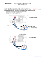
FRONT-PANEL CONTROLS
All controls and connectors required for the normal op-
eration of the Type 1S1 are located on the front panel of
the unit (see Fig. 21). To make full use of the capabilities
of the instrument, the operator should be familiar with the
function and use of each of these controls and connectors.
Brief descriptions are presented in Table 2-1 and further
information, if necessary, is included later in this section
under an appropriate heading. The nature of the input
signal and the triggering signal will determine the setting
of the controls.
TABLE 2-1
Functions of Controls and Connectors
VERTICAL
mVOLTS/CM
Switch
Selects vertical input deflection factor from
7 calibrated steps ranging from 200 mv/cm
to 2 mv/cm. Deflection factor is calibrated
only when mVolts/Cm VARIABLE control
is at CAL position and VERT GAIN ad-
justment is set correctly.
mVolts/cm
VARIABLE
Control
Varies vertical input deflection for adjust-
ing display amplitude between steps of
mVOLTS/CM switch. Extends deflection
factor to about 500[tv/cm from 2mv/cm
position of switch. When making voltage
measurements from display, be sure VARI-
ABLE control is set to CAL position. Does
not affect dc offset voltage measurement.
VERT
POSITION
Control
Positions display vertically on oscilloscope
crt screen. Positioning range is slightly
greater than 10cm. Further vertical posi-
tioning is provided by DC OFFSET control.
DC OFFSET
Control
Positions display vertically on oscilloscope
crt screen by adding internal dc voltage
(+1 volt to -1 volt) to vertical signal.
Amount of offset voltage added to signal
(multiplied X10) can be accurately moni-
tored at OFFSET OUTPUT jack.
OFFSET
OUTPUT Jack
Provides monitor output for determining
amount of offset voltage added by DC
OFFSET control. Voltage change at OFF-
SET OUTPUT jack is 10 times the vertical
signal dc level change produced by DC
OFFSET control. Output impedance is

Operating Instructions – Type 1S1
2-2
Fig. 2- 1. Front panel controls and connectors.

Operating Instructions – Type 1S1
2-3
10 k ohms. Measurement of offset voltage
should be made with high-impedance de-
vice.
SMOOTHING
Control
Reduces random display noise amplitude
when control is turned counterclockwise.
Noise may be decreased to approximately
rd of the value present at normal re-
sponse position (NORM). If display dot
density is low, smoothing reduces appar-
ent transient response of system.
PROBE POWER
Connector
Provides filament and plate voltages and
ground return for operation of cathode-
follower probe.
SIGNAL IN
Connector
Provides 50-ohm environment for applying
signal to input circuit of vertical system.
Connector is followed by trigger takeoff,
delay line, 50-ohm termination and sam-
pling gate. Dynamic operating range is
up to ±2 volts and maximum short-time
overload is approximately ±5 volts
(higher with reduced duty factor).
VERT OUTPUT
Jack
Provides real-time replica of signal applied
to oscilloscope vertical amplifier. Output
amplitude (through 10k ohms) is 200mv
per cm of calibrated display amplitude.
Includes dc offset voltage. If vertical signal
is driven out of dynamic range of sam-
pling amplifiers, signal at VERT OUTPUT
jack is distorted. Output signal can be
used in conjunction with horizontal output
to drive pen recorder or monitor
oscilloscope.
VERT GAIN
Adjustment
Adjust display amplitude to correspond to
deflection factor indicated by mVOLTS/CM
switch, when mVolts/Cm VARIABLE
control is at CAL position.
VAR BAL
Adjustment
Adjusts vertical balance so that with zero
offset voltage trace does not move verti-
cally when mVolts/Cm VARIABLE control
is rotated.
TRIGGERING
TRIGGER
SENSITIVITY
Control
Selects triggering signal level that starts
trigger circuit operation. Adjusts frequency
of synchronizing circuit for operation on
highfrequency triggering signals when
RECOVERY TIME control is switched into
SYNC position.
RECOVERY TIME
Control and SYNC
Switch
Adjusts duration of trigger holdoff interval
so that recovery occurs between cycles of
input triggering signal, thus providing
stable triggering regardless of triggering
signal repetition rate. Sets circuit for
synchronized operation when control is
switched to SYNC detent position at
counterclockwise end of rotation.
TRIGGER
SOURCE
Switch
Selects triggering signal from vertical
channel trigger takeoff or from EXT TRIG
input connector. Also selects either posi-
tive-going ( + ) or negative-going ( - )
slope of triggering signal. Disconnects
triggering signal and permits free run op-
eration of triggering circuit when switch is
set to FREE RUN position.
EXT TRIG
Connector
Permits application of external signal (ac-
coupled) for triggering sampling operation.
Primarily for use with small amplitude trig-
gering signals (from 5 mv to 200 mv) and
for obtaining time positioning not possible
with internal triggering. Also permits trig-
gering from a single source to retain time
relationships between different vertical in-
put signals and to avoid readjusting trig-
gering controls. One trigger is required
for each sample. For slowrise signals, 1
mv/µsec minimum rate of rise is required.
If triggering signal amplitude exceeds 200
mv, be sure to attenuate signal.
SWEEP
TIME/CM
(MAGNIFIER)
Switch
Operates with TIME POSITION RANGE
indicator to select display equivalent-time
sweep rate and time magnification. Cali-
brated steps range from 50 µsec/cm to 0.1
nsec/cm. Time magnification up to X100
is possible on sweep rates from 50 µsec/cm
to 1 nsec/cm, with no change in display
dot density. Magnification takes place
following a time reference point that re-
mains fixed at the left edge of the screen.
White dot on MAGNIFIER knob always
indicates display equivalent-time sweep
rate, even when magnified. Display is cali-
brated only when Time/Cm VARIABLE con-
trol is at CAL position and oscilloscope
horizontal deflection factor is adjusted to
1 volt/cm. Display repetition rate also
depends on display dot density and on
triggering signal repetition rote.
Time/Cm
VARIABLE
Control
Varies equivalent-time sweep rate con-
tinuously between steps of TIME/CM
switch. Sweep speed is increased from rate
indicated by TIME/CM switch as VARI-
ABLE control is turned clockwise. Can ex-
tend fastest sweep rate (.1 nSEC/CM) to
about 33 psec/cm. When making time
measurements from display, be sure
VARIABLE control is set to CAL position
(counterclockwise detent).
TIME
POSITION
RANGE
Indicator
Indicates time range through which TIME
POSITION and FINE controls can move
start of crt display "time-window." Range
is read on blue TIME POSITION RANGE
scale, as indicated by blue tab on clear
skirt of knob.
TIME
POSITION
And
FINE
Controls
Position start of sweep through time range
indicated by TIME POSITION RANGE
indicator to move display time window
and to position time-reference point for
magnification. Fully clockwise position
of each control provides minimum sam-
pling delay (maximum lead time).

Operating Instructions – Type 1S1
2-4
SAMPLES/CM
Control
Adjust number of samples (dots) displayed
per cm of horizontal displacement, and
thus adjusts display repetition rate, when
DISPLAY MODE switch is set to NORMAL
or SINGLE SWEEP. Normally is adjusted
for maximum resolution with minimum dis-
play flicker. Dot density is continuously
variable from approximately 5 samples/
cm to many thousands of samples/cm
In counterclockwise detent position (SWEEP
OFF), dot is displayed on crt screen and
may move extremely slowly across screen.
SAMPLES/CM control does not function
when DISPLAY MODE switch is at EXT
HORIZ or MAN positions.
DISPLAY MODE
Switch
Selects one of 4 modes of display pre-
sentation: NORMAL-Presents normal re-
petitive-sweep display; SINGLE SWEEP-
Presents single sweep of display each time
START button is pressed; EXT HORIZ-
Permits application of external sweep sig
nal through EXT HORIZ INPUT jack;
MAN-Permits manual scan of equivalent-
time display with MANUAL SCAN control.
START
(Pushbutton)
Switch
Starts single sweep of display when button
is pressed if DISPLAY MODE switch is
set to SINGLE SWEEP position. Sweep is
then held off until START button is pressed
again or until DISPLAY MODE switch is set
to another position.
MANUAL SCAN
or EXT HORIZ
ATTEN Control
Manually moves crt spot horizontally to
trace out equivalent-time display when
DISPLAY MODE switch is set to MAN.
Also serves as input attenuator for external
scan voltage applied to EXT HORIZ IN-
PUT jack when DISPLAY MODE switch is
set to EXT HORIZ position. In either case,
equivalent-time sweep rate of display is
same as when DISPLAY MODE switch is
set to NORMAL, and depends on setting
of TIME/CM switch.
EXT HORIZ
INPUT Jack
Permits application of external signal for
scanning equivalent-time display when
DISPLAY MODE switch is set to EXT HORIZ
position. Attenuation of input signal is
adjusted by EXT HORIZ ATTEN control,
and equivalent-time sweep rate of dis-
play is set by TIME/CM control. Deflection
factor is adjustable from 1 volt/cm to
more than 16 volts/cm.
HORIZ OUTPUT
Jack
Provides output waveform for driving hori-
zontal deflection of display oscilloscope.
Connection is made through oscilloscope
External Horizontal Input jack. Output
amplitude (through 10k ohms) is 1 volt
/cm, therefore the oscilloscope horizontal de-
flection factor must be set to 1 volt/cm for
correct equivalent-time sweep rates. Out-
put signal may be used for driving pen
recorder, since signal corresponds to real-
time vertical signal available through VERT
OUTPUT jack. When using normal stair
case sweep, duration of output staircase
steps depends on setting of SAMPLES/CM
control, repetition rate of trigger circuit,
and time position range used.
FIRST-TIME OPERATION
The first 18 steps of the following procedure describe
setting up the crt display when using a Type 1S1 and a dis-
play oscilloscope. These steps may be used in installing a
Type 1S1.
The remaining steps of the procedure demonstrate the
basic operation of the Type 1S1 front-panel controls. These
demonstration steps are not required for setting up the
sampling system.
1. With the display oscilloscope power turned off, insert
the Type 1S1 in the plug-in compartment.
2. Set the oscilloscope Intensity control counterclockwise.
3. Turn on the oscilloscope power switch.
4. Connect a banana/banana patch cord from the Type
1S1 HORIZ OUTPUT jack to the oscilloscope External
Horizontal Input jack.
5. Set the controls as follows:
Type 1S1
mVOLTS/CM 200
mVolts/Cm VARIABLE CAL
VERT POSITION Centered
DC OFFSET At center of 10-turn range
TIME POSITION Clockwise
FINE Centered
SMOOTHING NORM (Clockwise)
SAMPLES/CM Centered
DISPLAY MODE NORMAL
MANUAL SCAN
EXT HORIZ ATTEN Clockwise
TIME/CM 2 nSEC
Time/Cm VARIABLE CAL
TRIGGER SOURCE INT +
TRIGGER SENSITIVITY Clockwise
RECOVERY TIME Centered
Oscilloscope
Triggering controls Set to hold off sweep
Horizontal Display Ext X 1
Amplitude Calibrator 5 v
Crt Cathode Selector Chopped Blanking

Operating Instructions – Type 1S1
2-5
6. Adjust the oscilloscope Intensity control to display
a free-running trace of moderate brightness.
7. Adjust the DC OFFSET control to position the trace
near the horizontal centerline.
8. Adjust the oscilloscope External Horizontal Input Vari-
able control and Horizontal Position control to obtain ap-
proximately 10.2cm of horizontal deflection. If necessary,
set the Horizontal Display,switch to EXT X10.
9. Adjust the oscilloscope Focus and Astigmatism con-
trols for the best presentation. The dots should be small,
with equal vertical and horizontal dimensions.
10. Adjust the oscilloscope Trace Alignment control or
crt adjustment to align the trace with the horizontal center-
line.
11. Reset the Intensity control for a dim trace.
12. Remove the patch cord from the Type 1S1 HORIZ
OUTPUT jack and connect it between the oscilloscope Cali-
brator Output connector and the oscilloscope External
Horizontal Input jack. An adapter or a BNC/banana patch
cord may be required for the connection.
13. With the oscilloscope Horizontal Position control, posi-
tion the left dot to the 1-cm graticule line (see Fig. 2-2).
Fig. 2-2. Oscilloscope display for adjusting external horizontal
deflection factor (±4%).
14. Adjust the oscilloscope External Horizontal Input
Variable control and Horizontal Position control to position
the right-hand dot to the 6-cm graticule line while the left
dot is at the 1-cm line.
15. Check that this adjustment is correct by positioning
the pair of dots to the 4-cm and 9-cm graticule lines. If there
is a difference in deflection, adjust the External Horizontal
Input Variable control for a compromise setting.
16. Remove the patch cord from the Calibrator Output
connector and reconnect it between the Type 1S1 HORIZ
OUTPUT jack and the oscilloscope External Horizontal In-
put jack.
17. With the oscilloscope Horizontal Position control,,
position the start of the trace at the left edge of the graticule.
18. Before making any accurate voltage measurements
from the display, check the vertical gain adjustment by ap-
plying a signal from an accurate 50-ohm source, The oscillo-
scope calibrator cannot be used for this adjustment unless
it has an amplitude that is specified to be correct into 50
ohms.
19. Connect a positive-going pulse signal to the SIGNAL
IN connector through a 50-ohm coax cable and attenuators
as required. (A good signal for this purpose is a 600-mv 2-
nsec pulse with a repetition rate of about 70 kc, such as the
output pulse from a Tektronix Type 111 Pretrigger Pulse Gen-
erator applied through 20X attenuation). If the signal
amplitude is greater than 1 volt, peak to peak, attenuate it
with external attenuators. If the combined dc and peak ac
voltage is over 1 volt, ac-couple the signal with a coupling
capacitor at the SIGNAL IN connector.
20. Turn the TRIGGER SENSITIVITY control through its
range of rotation. Note that the display is free running
when the control is fully clockwise, that it is triggered when
the control is approximately midrange, and that the dis-
play is held off when the control is turned fully counter-
clockwise. (It may be necessary to increase the intensity
to view the triggered display.)
21. Set the TRIGGER SENSITIVITY control for a stable
triggered display.
Fig. 2-3. Typical oscilloscope display illustrating time magnification
of the display. Expansion takes place about the left edge of the screen.

Operating Instructions – Type 1S1
2-6
22. With the DC OFFSET control, position the display to
the center of the crt screen.
23. Turn the SAMPLES/CM control through its range of
rotation and note the change in dot density from about 5
samples/cm at the MIN (clockwise) position to many thou-
sands of samples/cm at the counterclockwise end of rotation.
CAUTION
Always decrease the crt beam intensity whenever
a stationary spot or slow-moving display is on
the screen. Excessively high intensity can damage
the crt screen.
24. Switch the SAMPLES/CM control to the SWEEP OFF
position. The displayed dot remains on the crt screen at the
position of the trace at the time the control was switched.
(The dot may move slowly across the screen.)
25. Switch the SAMPLES/CM switch out of SWEEP OFF
position and adjust it for as dense a trace as possible with
minimum display flicker.
26. With the TIME POSITION control, move the displayed
pulse to the left edge of the screen so that the trace starts
on the pulse rise (see Fig. 2-3).
27. Pull out on the MAGNIFIER knob and turn the TIME/
CM switch clockwise one position. Note that the display
time- magnification takes place at the left edge of the screen.
Also notice that there is no change in horizontal dot density.
Since the equivalent time per cm is decreased, however, the
dot density is increased in equivalent time, producing a
more continuous trace on the pulse rise.
28. Turn the TIME/CM switch to the .5 nSEC, .2 nSEC
and .1 nSEC positions. (It is not necessary to pull on the
MAGNIFIER knob except when intially disengaging it from
the TIME POSITION RANGE switch.) Observe the display
expansion.
29. Return the TIME/CM switch to 2 nSEC. The MAGNI-
FIER knob will automatically engage with the TIME POSI-
TION RANGE switch.
30. Set the DISPLAY MODE switch to SINGLE SWEEP.
31. Press the START button. A single triggered sweep
of the display is presented each time the START button is
pressed.
32. Set the DISPLAY MODE switch to MAN position.
33. Turn the red MANUAL SCAN (EXT HORIZ ATTEN)
knob slowly counterclockwise and note that the same pulse
display is traced out on the crt. The TIME/CM switch still
determines the equivalent-time sweep rate of the display and
the TIME POSITION control still determines the display posi-
tion.
34. Connect a patch cord from the oscilloscope Sawtooth
Output jack to the Type 1S1 EXT HORIZ INPUT jack.
35. Set the oscilloscope triggering controls for a free-
running sweep to generate a sawtooth output.
36. Set the oscilloscope Time/Cm switch to 10mSec.
37. Set the Type 1S1 DISPLAY MODE switch to the EXT
HORIZ position.
38. Adjust the Type 1S1 EXT HORIZ ATTEN control for a
horizontal deflection of about 10cm. Notice that in this
mode, similar to manual scan, the external horizontal in-
put voltage determines the crt spot position, but the Type 1S1
TIME/CM switch still determines the equivalent-time sweep
rate of the display. Since the external voltage merely scans
the display, the sawtooth voltage scans on both the ramp and
retrace portions of the sawtooth waveform.
39. Turn the SAMPLES/CM control. Notice that the dot
density of the display is not controlled by the SAMPLES/CM
control when the display is externally scanned, but is instead
controlled by the rate of scanning and by the trigger repe-
tition rate. (The same is true when the display is manually
scanned.)
40. Return the DISPLAY MODE switch to NORMAL.
41. Adjust the SAMPLES/CM control for a dense display
with minimum flicker.
42. Set the TIME POSITION control to position the pulse
display to the right of the vertical centerline.
43. Set the TRIGGER SOURCE switch to INT -.
44. Readjust the TRIGGER SENSITIVITY control if
necessary for a triggered display. Notice that the displayed
pulse has shifted to the left due to the fact that the triggering
occurs at essentially the same time, but now is on the
negative-going slope. (There is also a slight additional shift of 1
or 2 nsec due to the inverting transformer.)
45. Return the TRIGGER SOURCE switch to INT +.
46. Disconnect the pulse input signal.
47. Connect a 10-Mc sine wave of about 1 volt ampli-
tude (e.g. from a Tektronix Type 180A through 5X atten-
uation) to the SIGNAL IN connector.
48. Set the TIME/CM switch to 50nSEC.
49. Trigger the display with the TRIGGER SENSITIVITY
control. The control should be set to the most stable trigger-
ing point.
50. Slowly turn the RECOVERY TIME control through its
range of rotation. Note that several positions of the control
provide stable triggering of the display.
51. Switch the RECOVERY TIME control to SYNC posi-
tion.
52. Adjust the TRIGGER SENSITIVITY control for a stable
display. This synchronized mode of operation is normally
used for input signals from 20 Mc to 1 Gc.
53. Switch the RECOVERY TIME control out of SYNC posi-
tion and set it to midrange. Readjust the TRIGGER SEN-
SITIVITY control if necessary.
54. Turn the TIME POSITION and FINE controls fully
clockwise.
55. With the TIME/CM MAGNIFIER knob locked to the
TIME POSITION RANGE switch, set the TIME/CM switch to
20 nSEC. This sets the TIME POSITION RANGE switch to
500 nS. Each cycle of the 10-Mc waveform represents 100
nsec of time.
56. Observe the display while turning the TIME POSITION
control fully counterclockwise. Notice that approximately
4½ cycles of the waveform, representing approximately
450 nsec, pass the left edge of the crt screen.

Operating Instructions – Type 1S1
2-7
57. Turn the FINE control fully counterclockwise. Notice
that approximately ½ cycle of the waveform, representing 50
nsec, passes the left edge of the screen. Thus the total
positioning capability is 500 nsec, as indicated by the TIME
POSITION RANGE switch. The FINE control has about
1/10th of the time positioning range of the TIME POSITION
control.
58. Turn the TIME/CM switch to .2µSEC, setting the
TIME POSITION RANGE switch to 5µS.
59. Pull out on the MAGNIFIER knob and turn the TIME/
CM switch back to 20 nSEC. The sweep rate and display are
now the same as before, except that now the time position-
ing controls have a range of 5 µsec, and the display repeti-
tion rate is reduced.
60. Turn the FINE control through its range of rotation.
Notice that now the control moves approximately 4½
cycles of the waveform post the left edge of the crt screen.
(At this time position range, the TIME POSITION control
would move approximately 45 cycles of the waveform
through the edge of the "time window". Thus the total time
positioning capability is approximately 5 µsec, as indicated
by the TIME POSITION RANGE switch.)
61. Set the TIME/CM switch to .2µSEC to engage the
MAGNIFIER knob with the TIME POSITION RANGE switch,
then turn the TIME/CM switch to 1 nSEC. There is now
approximately 1/10th of a cycle displayed.
62. Position the top or bottom of the waveform to the
center of the screen with the TIME POSITION control.
63. Set the mVOLTS/CM switch to 2.
64. With the DC OFFSET control, position the tip of the
waveform on the screen.
65. Turn the SMOOTHING control fully counterclockwise.
Notice the decrease in display noise with smoothing.
66. Return the mVOLTS/CM switch to 200.
67. Set the TIME/CM switch to 5 nSEC.
68. With the SMOOTHING control set fully counterclock-
wise, turn the SAMPLES/CM control to MIN position (fully
clockwise). Notice the decrease in display amplitude, due to
the combination of full smoothing and minimum dot density.
This illustrates the need for a relatively high dot density
when smoothing is used.
69. Turn the SMOOTHING control to NORM (fully clock-
wise). The display amplitude is returned to normal, even with
minimum dot density.
70. Readjust the SAMPLES/CM control for a normal trace
with maximum dot density and minimum flicker.
71. Insert a 10X attenuator in the signal path.
72. Retrigger the dipslay with the TRIGGER SENSITIVITY
control.
73. Set the VERT POSITION control to midrange.
74. Center the trace with the DC OFFSET control.
75. Turn the VERT POSITION control through its range of
rotation. The overall range of the control is more than 10
cm, thus positioning the display off screen both upward and
downward. Leave the VERT POSITION control at midrange.
76. Turn the DC OFFSET control fully counterclockwise,
then fully clockwise. Notice that the positioning capability
of the control is more than ±5cm, representing ±1 volt at
this 200mv/cm deflection factor.
77. Set the mVOLTS/CM switch to 20.
78. Turn the DC OFFSET control and notice that the dis-
play positioning capability has increased, since at this de-
flection factor the ±1 volt offset provides ±50 cm of posi-
tioning. (At 2 mv/cm the positioning range is ±500 cm.)
79. Center the trace with the DC OFFSET control.
80. Turn the VERT POSITION control through its range
of rotation. Notice that this control still has approximately
10cm of positioning capability. This is true regardless of the
input deflection factor.
81. Disconnect the input signal. This concludes the dem-
onstration of front-panel control functions.
OPERATIONAL ADJUSTMENTS
Whenever the Type 1S1 is transferred from one oscillo-
scope to another, the external horizontal deflection factor
of the oscilloscope must be adjusted to 1 volt/cm and the
vertical gain of the system should be checked.
Occasional checks should also be made of the smoothing
balance, the vertical attenuator balance, the attenuator
variable balance and the vertical position range. In general,
the need for the balance and position adjustments will be
obvious from the display, as described below. Allow at
least 20 minutes warm up of the Type 1S1 before making any
of these adjustments.
In addition to these normal operational checks, it may
sometimes be necessary to check the sampling loop gain if
the display seems to have an incorrect amount of overshoot
or rolloff.
Horizontal Deflection Adjustment
To provide correct equivalent-time sweep rates, the
horizontal deflection factor of the oscilloscope must be
adjusted to 1 volt/cm to match the calibrated 1 volt/cm
horizontal output of the Type 1S1. Any accurate low-imped-
ance voltage signal or dc voltage source from about 4 volts
to 8 volts in amplitude can be used for making this adjust-
ment.
One method, using the oscilloscope calibrator 5-volt
square-wave signal, has been described under "First-Time
Operation". This method is easy and fast but provides an
accuracy within only about 4%, including about 1 % pos-
sible error in reading the display. If the oscilloscope 5-volt
calibrator signal amplitude is more accurate than the 3%
tolerance, the timing error may be much less than 4%. On
the other hand, if the calibrator signal is not exactly 5
volts, but its amplitude is accurately known, the deflection
factor can also be adjusted accurately by setting the centi-
meters of deflection to equal the known amplitude in volts.
Another method of adjusting the horizontal deflection
factor is given in the timing calibration adjustment in Section
5. This method, which provides an accuracy within about
1 %, uses a differential comparator oscilloscope for adjust-
ing the square-wave amplitude to within 0.5% of 8 volts.

Operating Instructions – Type 1S1
2-8
Use either of these methods, as described in the proce-
dures, or make use of some other accurate voltage source.
The differential comparator can be used to check the 5-volt
calibrator amplitude, after which the horizontal deflection
adjustment can be made to within about 2% accuracy with
only the calibrator signal.
Smoothing Balance Adjustment
If the trace (with no signal applied) moves vertically as
the SMOOTHING control is turned, adjust the smoothing
(memory) balance adjustment as follows:
1. Remove the left side panel of the oscilloscope (or ex-
tend a rack-mounted oscilloscope).
2. Locate the MEMORY BAL adjustment control (R110)
shown in Fig. 2-4.
3. Alternately adjust the control, then turn the SMOOTH-
ING control, until there is no vertical trace movement as
the SMOOTHING control is turned.
While the oscilloscope side panel is off, also check the
attenuator and variable balance adjustments and the vertical
position range adjustment as given in the following pro-
cedures.
Attenuator Balance Adjustment
With the dc offset at zero volts and with no signal applied,
if the trace moves vertically on the crt screen as the
mVOLTS/CM switch is turned from one position to another,
adjust the attenuator balance as follows:
1. First check and adjust the smoothing balance as de-
scribed above.
2. Set the DC OFFSET control to zero volts by monitoring
the OFFSET OUTPUT jack with a high-impedance voltmeter
or a dc-coupled test oscilloscope. Another method of setting
the dc offset to zero volts is by moving the patch cord con-
nector from the HORIZ OUTPUT jack to the OFFSET OUTPUT
jack to monitor the offset voltage. When the output voltage
is zero, the crt spot will not move horizontally as the patch
cord connector is touched to or removed from the OFFSET
OUTPUT jack.
3. With the mVOLTS/CM switch at 200, position the free-
running trace on the horizontal centerline with the VERT
POSITION control.
4. Set the mVOLTS/CM switch to 2.
5. Locate the BRIDGE BAL adjustment control (R30) shown
in Fig. 2-4.
6. Adjust R30 to reposition the trace to the center of the
crt screen.
7. Repeat steps 3 and 4 to check the adjustment.
Variable Balance Adjustment
With the dc offset at zero volts and with no signal applied,
if the trace moves vertically on the crt screen as the mVolts/
Cm VARIABLE control is rotated, adjust the variable balance
as follows:
1. First check and adjust the smoothing balance and at-
tenuator balance as described above.
Fig. 2-4. Operational adjustment controls on the left side of the Type 1S1

Operating Instructions – Type 1S1
2-9
2. Set the DC OFFSET control for zero volts at the OFF-
SET OUTPUT jack.
3. Set the mVOLTS/CM switch to 200.
4. Turn the mVolts/Cm VARIABLE control clockwise to the
point of maximum sensitivity.
5. With the VERT POSITION control, position the free-
running trace to the horizontal centerline.
6. Return the mVolts/Cm VARIABLE control to the CAL
detent position.
7. With a small screwdriver, adjust the front-panel VAR
BAL control to return the trace to the horizontal centerline.
8. Repeat steps 4, 5 and 6 to check the adjustment.
9. Leave the mVolts/Cm VARIABLE control set to the CAL
position.
Vertical Position Range Adjustment
With the dc offset at zero volts and with no signal applied,
if the VERT POSITION control does not have enough range
to move the trace off the screen in one direction or the other,
the position range control may need to be adjusted. First,
however, check the 3 balance adjustments given above. If
the balance adjustments are correct but the range of the VERT
POSITION control is not correct, make the adjustment as
follows:
1. Set the DC OFFSET control for zero volts at the OFF-
SET OUTPUT jack.
2. Center the VERT POSITION control so that the white
dot points straight up.
3. Locate the POSITION RANGE adjustment control (R194)
shown in Fig. 2-4.
4. Adjust R194 to position the free-running trace to the
horizontal centerline.
Vertical Gain Adjustment
The vertical gain of the Type 1S1 should be adjusted when
the unit is first installed in an oscilloscope and should be
checked occasionally thereafter.
The use of a 50-ohm amplitude calibrator, as described in
the calibration procedure in Section 5, is recommended for
this adjustment. The procedure given there provides an
accuracy within about 1%.
Another method of checking the vertical gain can be used
if the oscilloscope 1-kc calibrator has a position that is cali-
brated into 50 ohms (e.g. 0.1 V Into 50 at the .5 Volts
position). However, since the calibrator tolerance is ±3%,
accuracy of the check with the oscilloscope calibrator will
be only within about 4%, unless the amplitude error is known.
The following procedure is suggested for use of the 0.1 V
Into 50 calibrator signal:
1. Set the TIME/CM switch to 50 µsec.
2. Connect the oscilloscope calibrator directly to the
Type 1S1 SIGNAL IN connector through an adapter and a
coax cable.
3. Set the calibrator to the 0.1 V into 50 position,
4. Set the Type 1S1 mVOLTS/CM switch to 20.
5. Trigger the crt display with the TRIGGER SENSITIVITY
control.
6. Check for 5cm of vertical deflection (see Fig. 2-5).
If the amount of error in the calibrator signal is known, check
the display for a vertical deflection of 200mv/cm.
Fig. 2-5. Typical oscilloscope display for checking vertical
deflection factor (±4%) with oscilloscope calibrator.
7. If the vertical gain is not correct, use a small screw-
driver to adjust the front-panel VERT GAIN control.
Loop Gain Adjustment
To present a correct display on the crt screen when using
a low dot density, the dot transient response of the sampling
channel must be correct. That is, the gain of the sampling
feedback loop must be set so that each display dot ac-
curately represents the signal level at the time the sample
was taken. If loop gain is greater than unity (gain of 1),
the display will be excessively noisy and have overshoot.
If loop gain is less than unity, the rising portions of fast
pulses will be rolled off when using a low dot density, and
the display amplitude will be decreased for sine waves.
In the Type 1S1, loop gain is adjusted to unity with the
SMOOTHING control set to the fully clockwise NORM posi-
tion. The SMOOTHING control can then be used to decrease
loop gain when necessary to reduce display noise.
Use a 1-volt 40-kc fast-rise pulse approximately 20 nsec
in duration, as described in the calibration procedure, for
checking loop gain. This check causes the loop to process
a 1-volt change between each two samples, thus detecting
any variation from unity gain.
INPUT SIGNAL CONNECTIONS
General Information
The input circuits for both the vertical signal and the
external triggering signal are designed to have the character

Operating Instructions – Type 1S1
2-10
istics of a 50-ohm transmission line. This permits the use of
50-ohm coax cables for applying the input signals with mini-
mum signal loss or distortion.
When connecting the signal from the source to the Type
1S1, many factors must be taken into consideration including
loading of the source, signal losses in the cables, time delay,
coupling and attenuating the signal, and matching imped-
ances. This portion of the manual discusses these factor with
respect to the vertical input signal. Connections for applying
an external triggering signal are discussed later under "Trig-
gering the Display".
Coax Cables
Signal cables that connect the vertical signal from the
source to the Type 1S1 SIGNAL IN connector should have a
characteristic impedance of 50 ohms. Impedances other
than 50 ohms will cause reflections that will make it difficult
to interpret the display. High-quality low-loss coaxial cables
should be used to insure that all the information obtained at
the source will be delivered to the Type 1S1 vertical input.
If it is necessary to use cables with characteristic impedances
other than 50 ohms, suitable impedance-matching devices will
aid in the transition.
The characteristic impedance, velocity of propagation and
nature of signal losses in a coaxial cable are determined by
the physical and electrical characteristics of the cable. Losses
caused by energy dissipation in the dielectric are proportional
to the signal frequency. Therefore much of the high-fre-
quency information in a fast-rise pulse can be lost in a very
few feet of interconnecting cable.
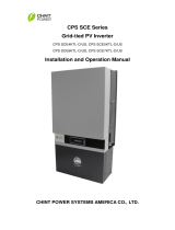
Fig. 2-6. shows the relative increase in output signal rise-
time when a step input signal is passed through several types
of commonly used 50-ohm coax cables. This increase in out-
put risetime must be taken into consideration when making
risetime determinations. For example, a length of cable with
a 225-psec output risetime will degrade a 500-psec input rise-
time by about 10%. (This may be determined by the "root
of the sum of the squares" formula.) As can be seen from
the graph, it takes only 6 feet (9 nsec) of RG-58A/U cable to
cause this 10% change. However, it will take about 15 feet
(22.5nsec) of RG-8A/U or 80 feet (95nsec) of Spir-o-line to
cause the same amount of change. If signal delay greater
than 60nsec is required, the use of a Tektronix Type 113
Delay Cable is recommended.
It is important to note that the risetime of the transmitted
signal deteriorates approximately in proportion to the square
of the length of the cable. As an illustration, a 500-psec rise-
time would be increased to 1000psec (100% increase) by
a length of cable with a risetime of about 867 psec. From
Fig. 2-6 it is seen that approximately 10 feet (15 nsec) of RG-
58A/U, 25 feet (37.5 nsec) of RG-8A/ U or 115 feet (137 nsec)
of Spir-o-line would cause this amount of risetime change.
Comparing this result with the previous determination, it
is seen that a 67% increase in cable length would produce
a 900% increase in risetime deterioration for the 500-psec
pulse risetime.
Due to the high-frequency losses in coax cables, the
0-50% half-amplitude risetime ("T nought", T
0
) is often used
instead of the 10-90% measurement that is used with ampli-
fiers. T
0
is approximately equal to 1/30th the 10-90% rise-
time of the coax cable output.
Occasionally, it may be desirable to use long 50-ohm
cables to move reflections out of the "time window" of
interest (delayed by double the transit time of the cable).
Keep in mind, however, the degrading effect that long
lengths of delay cable have on the pulse risetime.
Coupling
If there is a dc voltage greater than ±2 volts associated
with the signal source, a coupling capacitor must be used to
block the dc voltage. If a capacitor is not used, the signal
will be offset and will not be positionable on the screen.
In addition, voltage in excess of ±5 volts may damage the input
circuitry.
Attenuation
Maximum signal amplitude that should be applied to the
Type 1S1 SIGNAL IN connector is ±2 volts, combined dc
and peak ac. If the signal amplitude at the source is too
great, use an attenuator probe and/or externally-connected
T-attenuators. The attenuators that are used must have a
bandpass to about 2 Gc to avoid reducing the performance
of the system. High-quality 50-ohm attenuators are available
with attenuation factors of 10X, 5X and 2X. When the
attenuators are stacked, their attenuation factors multiply.
Thus, two 10X attenuators produce a 100X attenuation
factor.
Impedance Matching
To provide a smooth transition between devices of different
characteristic impedance, each device must encounter a
total impedance equal to its own characteristic impedance.
Thus, when a signal is applied to the Type 1S1 SIGNAL IN
connector, if the source impedance of the signal is not 50
ohms, a suitable impedance-matching device must be pro-
vided. If the impedances are not matched, reflections and
standing waves in the cables will result in distortion of the
displayed waveform.
Fig. 2-
6. Output signal risetime in response to a step input, given as
a function of cable length for some common coaxial cables.

Operating Instructions – Type 1S1
2-11
In many cases, insertion of a 50-ohm attenuator in the sig-
nal path will provide an approximate impedance match
and will absorb most reflections. It should be noted, how-
ever, that the attenuation factor will not be the same as
it would be if the impedances were the same on both sides.
Fig. 2-7. Simple resistive impedance-matching network providing
minimum attenuation.
Fig. 2-7 illustrates a simple resistive impedance-matching
network that provides minimum attenuation. To match imped-
ances with the network, the following conditions must exist:
(
)
( )
221
221
RZR
RZR
++
+
must equal Z
1
; and
21
21
1
RZ
RZ
R
+
+
must equal Z
2
.
Therefore:
R
1
Z
2
= Z
1
Z
2
; and R
1
Z
1
= R
2
(Z
2
-Z
1
)
or R
1
=
)(
122
ZZZ −
;
and R
2
=
12
2
1
ZZ
Z
Z
−
As an example, to match a 50-ohm system to a 125-ohm
system:
Z
1
= 50 ohms; and Z
2
= 125 ohms.
Therefore:
R
1
=
)50125(125 −
= 96.8 ohms
and R
2
=
50125
125
50
−
= 64.6 ohms
When constructing such a device, the environment sur-
rounding the components should also be designed to provide
a transition between the impedances. Keep in mind that the
characteristic impedance in a coaxial system is determined
by the ratio between the outside diameter of the inner
conductor and the inside diameter of the outer conductor
(Z
0
= 138 log
10
D
1
/D
2
)
Though the network in Fig. 2-7 provides minimum atten-
uation for a purely resistive impedance-matching device, the
attenuation as seen from one end does not equal that seen
from the other end. A signal applied from the lower imped-
ance source (Z
1
) encounters a voltage attenuation (A
1
) that
may be determined as follows:
Since: i
R1
= i
Z2
;
1
21
R
EE
−
=
2
2
Z
E
Therefore:
)21(;1
1
2
1
2
1
1
<<+== A
Z
R
E
E
A
A signal applied from the higher impedance source (Z
2
)
will encounter a greater voltage attenuation [A
2
) that may
be determined similarly:
Since: i
R1
= i
R2
+ i
z1
;
1
12
R
EE
−
=
1
1
2
1
Z
E
R
E
+
Therefore: A
2
=
1
2
E
E
=
1
1
1
2
1
++
Z
R
R
R
;
)
2
1(
1
2
2
Z
Z
A <<
In the example of matching 50 ohms to 125 ohms,
;77.11
6
.
64
8.96
1
=+=A
and
44.41
50
8.96
6
.
64
8.96
2
=++=A
Note that if the 50-ohm source were used for pulsing a
high-impedance load, R
1
would approximately equal the
impedance of the load (high R) and R
1
would approximately
equal the 50 ohms of the pulse source. In this situation, volt-
age attenuation would be about 2.
If a low-impedance load (<50 ohms) were to be en-
countered, the 50-ohm pulse source would be the Z
2
source.
If the load impedance were to approach 0 ohms, the value
of R
1
would then approach the load impedance (low R).
Voltage attenuation in this case would become quite signifi-
cant:
Attenuation =
L
Z
Z
2
2
=
L
Z
100
(very high)
The illustrated network can be modified to provide dif-
ferent attenuation ratios by adding another resistor (<R
1
)
in series between Z
1
and the junction of R
1
and R
2
.
Probes
For relatively high-impedance measurements of nanosec-
ond signals, special passive or cathode-follower signal probes
are available for use with the Type 1S1 Sampling Unit. Pas-
sive probes may also be built into or onto the circuits to be
monitored, to minimize changes in loading.
/