Page is loading ...

Heat Controller, Inc. • 1900 Wellworth Ave. • Jackson, MI 49203 • (517)787-2100 • www.heatcontroller.com
INSTALLATION, OPERATION
& MAINTENANCE MANUAL
R-410A Water-to-Water Series:
HWW Water-Source Heat Pumps

1
Model Nomenclature ..................................................2
Storage .......................................................................4
Pre-Installation............................................................4
Physical Data..............................................................5
Dimensional Data .......................................................6
Unit Installation ...........................................................7
Piping Installation .......................................................7
Load Plumbing Installation .........................................8
Water Loop Applications .............................................9
Open Loop - Ground Water Systems .......................10
Water Quality Standards ..........................................10
Ground Loop Applications ...................................11-13
Electrical - Line Voltage .......................................14,16
Electrical - Accessories.............................................15
Water Valve Wiring ...................................................15
Electrical - Low Voltage Wiring .................................17
Electrical Wiring Schematics ...............................18-19
CXM Controls ......................................................20-22
Piping System Cleaning & Flushing .........................23
Unit and System Checkout Procedure .....................24
Start Up Procedure ..............................................25-26
Operating Pressures............................................27-28
Preventive Maintenance ...........................................29
Refrigeration Troubleshooting Form .........................30
TABLE OF CONTENTS
Installation & Operation WATER-TO-WATER (HWW) SERIES Heat Controller, Inc.

2
Heat Controller, Inc. WATER-TO-WATER (HWW) SERIES Installation & Operation
Page 21
7 May, 2009
HEAT CONTROLLER OEM PRICE LIST
HWW HIGH EFFICIENCY Water-to-Water HFC-410a Heat Pumps
The basic unit price includes sealed heat pump refrigerant circuit.
• Cabinet - Heavy gauge galvanized steel with black polyester powder
coat paint – multiple removable panels for service access – stainless
steel front access panel(s) – interior surfaces lined with ½ inch dual
density acoustic type glass ber insulation – IPT water connections –
high and low voltage knockouts.
• Controls - Solid state control system with seven standard safeties
including anti-short cycle, over voltage, under voltage, high refrigerant
pressure, loss of refrigerant charge, low source water temperature,
low load water temperature – run and fault lights on cabinet exterior –
alarm contact for remote monitoring of fault condition ( eld selectable
for dry contact or 24vac).
• Refrigerant Circuit - Compressor(s) – coaxial source and load heat
exchangers – revering valve(s) – lter driers(s) – thermal expansion
valve(s) – high pressure and loss of charge switches – high and low
side Schrader ports for service – non-ozone depleting HFC-410a
refrigerant.
• Compressor(s) - High ef ciency scroll compressor - internally sprung
and externally isolated using dual vibration isolation system for
quiet operation. Mounting system includes rubber grommet mounts
between the compressor and a mounting tray then another set of
rubber mounts between the mounting tray and unit base pan.
• Reversing Valve - 4-way pilot operated, solenoid activated in cooling
mode.
• Safety Agency Listing - Product is ETL Listed.
• Application - May be applied in water loop heat pump, ground water
heat pump, and ground loop heat pump applications.
Entering Water Temperature Range: 20 - 110°F (-6.7 - 43.3°C)
Sizes 036, 060 & 120
HWW Model Structure
Basic Unit Description:
H W W A0 3 6 C1 1 0 C F C
1 2 3 4 5 6 7
8
9 10 11 12 13 14
HW = HEAT CONTROLLER SERIES HIGH EFFICIENCY
MODEL TYPE
W = WATER TO WATER
CONFIGURATION
UNIT SIZE
036 - 1,3,4
060 - 1,3,4,5
120 - 1,3,4,5
REVISION LEVEL
A = CURRENT
VOLTAGE
CONTROLS
0 = RESIDENTIAL ( 208-230/60/1 ONLY)
CABINET INSULATION
HOT WATER GENERATOR OPTIONS
C = Copper
SOURCE WATER COIL OPTIONS
N = Cupro-Nickel
C = Copper
LOAD WATER COIL OPTIONS
N = Cupro-Nickel
0 = NONE
1 = HWG w/INTERNAL PUMP (RESIDENTIAL)
F = FRONT
WATER CONNECTION LOCATION
1 = COMMERCIAL EXTENDED RANGE
VOLTAGE
2 = HWG COIL ONLY (COMMERCIAL)
C = CXM (ETL for USA & CANADA)
1 = 208-230/60/1 - 410A
3 = 208-230/60/3 - 410A
4 = 460/60/3 - 410A
5 = 575/60/3 - 410A
}
polyster powder
R-410A
HWW HIGH EFFICIENCY Water-to-Water R-410A Heat Pumps
• Cabinet- Heavy gauge galvanized steel with polyester powder
coat paint – multiple removable panels for service access – interior
surfaces lined with 1/2 inch dual density acoustic type glass
ber insulation – IPT water connections – high and low voltage
knockouts.
A=CURRENT 036
B=CURRENT 060, 120

3
Installation & Operation WATER-TO-WATER (HWW) SERIES Heat Controller, Inc.
General Information
� WARNING! �
� WARNING! �
� CAUTION! �
Safety
Warnings, cautions and notices appear throughout this
manual. Read these items carefully before attempting any
installation, service or troubleshooting of the equipment.
DANGER:Indicates an immediate hazardous situation, which
if not avoided will result in death or serious injury. DANGER
labels on unit access panels must be observed.
WARNING: Indicates a potentially hazardous situation, which
if not avoided could result in death or serious injury.
CAUTION: Indicates a potentially hazardous situation or an
unsafe practice, which if not avoided could result in minor or
moderate injury or product or property damage.
NOTICE: Notication of installation, operation or maintenance
information, which is important, but which is not hazard-
related.
WARNING! To avoid the release of refrigerant into the
atmosphere, the refrigerant circuit of this unit must be
serviced only by technicians who meet local, state, and
federal prociency requirements.
WARNING! All refrigerant discharged from this unit must
be recovered WITHOUT EXCEPTION. Technicians must
follow industry accepted guidelines and all local, state,
and federal statutes for the recovery and disposal of
refrigerants. If a compressor is removed from this unit,
refrigerant circuit oil will remain in the compressor. To
avoid leakage of compressor oil, refrigerant lines of the
compressor must be sealed after it is removed.
CAUTION! To avoid equipment damage, DO NOT use
these units as a source of heating or cooling during the
construction process. The mechanical components and
lters will quickly become clogged with construction dirt
and debris, which may cause system damage.

4
Heat Controller, Inc. WATER-TO-WATER (HWW) SERIES Installation & Operation
General Information
Inspection
Upon receipt of the equipment, carefully check the shipment
against the bill of lading. Make sure all units have been re-
ceived. Inspect the carton or crating of each unit, and inspect
each unit for damage. Assure the carrier makes proper nota-
tion of any shortages or damage on all copies of the freight bill
and completes a common carrier inspection report. Concealed
damage not discovered during unloading must be reported
to the carrier within 15 days of receipt of shipment. If not led
within 15 days, the freight company can deny the claim without
recourse. Note: It is the responsibility of the purchaser to
le all necessary claims with the carrier.
Storage
Equipment should be stored in its original packaging in a
clean, dry area. Store units in an upright position at all times.
The stack limit for HWW36, 060 and 120 is three.
Unit Protection
Cover units on the job site with either shipping packaging,
vinyl lm, or an equivalent protective covering. Cap the open
ends of pipes stored on the job site. In areas where painting,
plastering, and/or spraying has not been completed, all due
precautions must be taken to avoid physical damage to the
units and contamination by foreign material. Physical damage
and contamination may prevent proper start-up and may result
in costly equipment clean-up.
Examine all pipes, ttings, and valves before installing any of
the system components. Remove any dirt or trash found in or
on these components.
Pre-Installation
Installation, Operation, and Maintenance instructions are
provided with each unit. The installation site chosen should
include adequate service clearance around the unit. Before
unit start-up, read all manuals and become familiar with the
unit and its operation. Thoroughly check the system before
operation.
Prepare units for installation as follows:
1. Compare the electrical data on the unit nameplate with
ordering and shipping information to verify that the cor-
rect unit has been shipped.
2. Keep the cabinet covered with the shipping packaging
until installation is complete and all plastering, painting,
etc. is nished.
3. Verify refrigerant tubing is free of kinks or dents and that
it does not touch other unit components.
4. Inspect all electrical connections. Connections must be
clean and tight at the terminals.
� CAUTION! �
CAUTION! All three phase scroll compressors must
have direction of rotation veried at start-up. Verication
is achieved by checking compressor Amp draw. Amp
draw will be substantially lower compared to nameplate
values. Additionally, reverse rotation results in an ele-
vated sound level compared to correct rotation. Reverse
rotation will result in compressor internal overload trip
within several minutes. Verify compressor type before
proceeding.
� CAUTION! �
CAUTION! DO NOT store or install units in corrosive
environments or in locations subject to temperature or
humidity extremes (e.g., attics, garages, rooftops, etc.).
Corrosive conditions and high temperature or humid-
ity can signicantly reduce performance, reliability, and
service life. Always move and store units in an upright
position. Tilting units on their sides may cause equip-
ment damage.
� CAUTION! �
CAUTION! CUT HAZARD - Failure to follow this caution
may result in personal injury. Sheet metal parts may
have sharp edges or burrs. Use care and wear appropri-
ate protective clothing, safety glasses and gloves when
handling parts and servicing heat pumps.
NOTICE! Failure to remove shipping brackets from
spring-mounted compressors will cause excessive
noise, and could cause component failure due to
added vibration.

5
Installation & Operation WATER-TO-WATER (HWW) SERIES Heat Controller, Inc.
Unit Physical Data
Model 036 060 120
Compressor (qty) Scroll (1) Scroll (2)
Factory Charge R410A (lbs) [kg] Per Circuit 4.5 [2.04] 5.5 [2.49] 5.5 [2.49]
Water Connection Size
Source/Load (in)
Residential 1" Swivel 1” Swivel
1-1/2 IPT
Commercial 3/4” IPT 1” IPT
HWG (in)
Residential 1" Swivel 1” Swivel
1/2" IPT
Commercial 1/2” IPT 1/2” IPT
Weight - Operating (lbs) [kg] 348 [158] 360 [163] 726 [329]
Weight - Packaged (lbs) [kg] 373 [169] 385 [175] 770 [349]
Water Volume (Source)
Gallons (Liters) 0.96 (3.64) 1.33 (5.04) 2.65 (10.02)
Dual isolated compressor mounting
Balanced port expansion valve (TXV)
Insulated Source and Load Water Coils standard
Insulated Refrigerant Circuit standard
Compressor on (green) and fault (red) light

6
Heat Controller, Inc. WATER-TO-WATER (HWW) SERIES Installation & Operation
Unit Dimensional Data: HWW 036–120
B
C
A
M
L
K
1.0
(2.5 cm)
1
2
3
4
5
6
J
H
G
F
E
D
1
2
3
4
5
6
Required
Service Access
Optional
Service Access
Required
Service Access
Optional
Service Access
B
C
A
1.0
(2.5 cm)
1.8
(4.6 cm)
1.3
(3.3 cm)
2.7
(6.9 cm)
7.3
(18.5
cm)
1.7
(4.3 cm)
B
C
A
M
L
K
1.0
(2.5 cm)
1
2
3
4
5
6
J
H
G
F
E
D
1
2
3
4
5
6
Required
Service Access
Optional
Service Access
Required
Service Access
Optional
Service Access
B
C
A
1.0
(2.5 cm)
1.8
(4.6 cm)
1.3
(3.3 cm)
2.7
(6.9 cm)
7.3
(18.5
cm)
1.7
(4.3 cm)
Notes:
1. Front & side access is preferred for service
access. However, all components may be
serviced from the front access panel if side
access is not available.
2. While clear access to all removable panels
is not required, installer should take care
to comply with all building codes and allow
adequate clearance for future eld services.
Water to
Water
Overall Cabinet
Water Connections
Electric Access Plugs
1 2 3 4 5 6
A
Depth
B
Width
C
Height
D
Source
(Outdoor)
Water In
E
Source
(Outdoor)
Water Out
F
Load
(Indoor)
Water In
G
Load
(Indoor)
Water Out
H
HWG
Return In
J
HWG
Water
Out
K
Low
Voltage
L
External
Pump
M
Power
Supply
036-060
in. 30.6 25.4 33 2.7 9.4 19.4 24.5 27.9 30.4 20.9 22.9 30.9
cm. 77.8 64.5 83.8 6.9 23.9 49.3 62.2 70.9 77.2 53.1 58.2 78.5
120
in. 30.6 52.9 37 25.2 25.2 30.1 30.1 34.9 34.9 29.9 31.9 34.4
cm. 77.8 134.4 94 64.0 64.0 76.5 76.5 88.6 88.6 75.9 81.0 87.4

7
Installation & Operation WATER-TO-WATER (HWW) SERIES Heat Controller, Inc.
Unit Installation
HWW Unit Location
These units are not designed for outdoor installation. Locate
the unit in an INDOOR area that allows enough space for ser-
vice personnel to perform typical maintenance or repairs.
The installation of water source heat pump units and all as-
sociated components, parts and accessories which make up
the installation shall be in accordance with the regulations of
ALL authorities having jurisdiction and MUST conform to all
applicable codes. It is the responsibility of the Installing Con-
tractor to determine and comply with ALL applicable codes and
regulations.
Locate the unit in an indoor area that allows easy removal of
access panels, and has enough space for service personnel
to perform maintenance or repair. Provide sufcient room to
make water and electrical connections.. Any access panel
screws that would be difcult to remove after the unit is in-
stalled should be removed prior to setting the unit. These units
are not approved for outdoor installation and, therefore, must
be installed inside the structure being conditioned. Do not
locate in areas where ambient conditions are not maintained
within 40-100°F [4-38°C].
Installation of Supply and Return Piping
Follow these piping guidelines.
1. Install a drain valve at the base of each supply and
return riser to facilitate system ushing.
2. Install shut-off / balancing valves and unions at each
unit to permit unit removal for servicing.
3. Place strainers at the inlet of each system
circulating pump.
4. Select the proper hose length to allow slack between
connection points. Hoses may vary in length by +2% to
-4% under pressure.
5. Exceeding the minimum bend radius may cause the
hose to collapse which reduces water ow rate. Install
an angle adapter to avoid sharp bends in the hose
when the radius falls below the required minimum and
causes a slight kink.
Insulation is not required on loop water piping except where
the piping runs through unheated areas or outside the build-
ing or when the loop water temperature is below the minimum
expected dew point of the pipe ambient temperature. Insula-
tion is required if loop water temperature drops below the dew
point.
Pipe joint compound is not necessary when Teon threaded
tape is pre-applied to hose assemblies or when ared-end
connections are used. If pipe joint compound is preferred,
use compound only in small amounts on the pipe threads of
the tting adapters. Prevent sealant from reaching the ared
surfaces of the joint.
Note: When anti-freeze is used in the loop, assure that it is
compatible with Teon tape or pipe joint
compound employed.
Maximum allowable torque for brass ttings is 30 ft-lbs [41
N-m]. If a torque wrench is not available, tighten nger-tight
plus one quarter turn. Tighten steel ttings as necessary.
Piping Installation
� WARNING! �
� WARNING! �
Piping must comply with all applicable codes.
Do not bend or kink supply lines or hoses.
Optional pressure-rated hose assemblies designed specically
for use with Heat Controller units are available. Similar hoses
can be obtained from alternate suppliers. Supply and return
hoses are tted with swivel-joint ttings at one end to prevent
kinking during installation.
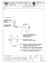
Refer to Figure 1 for an illustration of a Supply/Return Hose
Kit. Male adapters secure hose assemblies to the unit and ris-
ers. Install hose assemblies properly and check them regularly
to avoid system failure and reduced service life.
� CAUTION! �
Corrosive system water requires corrosion resistant ttings
and hoses and possibly water treatment.
Figure 1: Supply/Return Hose Kit
Rib Crimped
Length
(2 ft [0.6m] Length Standard)
Swivel
Brass
Fitting
Brass
Fitting
EPT
Reborde Acanalado
Longitud
(Long. Estándar de 2 pies)
Accesorio
Giratorio
de Bronce
Accesorio
de Bronce
MPT
Gasket
Swivel Nut
Stainless steel
snap ring
Brass Adaptor
Hand Tighten
Only !
Do Not
Overtighten !

8
Heat Controller, Inc. WATER-TO-WATER (HWW) SERIES Installation & Operation
Load Plumbing Installation
HWW Unit Load Plumbing
The applications are too varied to describe in this document.
However, some basic guidelines will be presented. Much of
the discussions on water loop applications would be valid for
the load plumbing discussion as well. All plumbing should
conform to local codes with the following considerations:
Wide temperature variation applications such as
heating/cooling coils:
- Employ piping materials that are rated for the maxi-
mum temperature and pressure combination. This
excludes PVC for most heating applications.
- Insure that load water ow in high temperature heat-
ing applications is at least 3 gpm per ton [3.9 l/m per
kW] to improve performance and reduce nuisance
high pressure faults.
- DO NOT employ plastic to metal threaded joints
- Utilize a pressure tank and air separator vent system
to equalize pressure and remove air.
Swimming Pool Hot Tub Applications:
- Load coax should be isolated with secondary heat
exchanger constructed of anti-corrosion material in all
chlorine/bromine uid applications.
Potable Water Applications:
- Load coax material should always be vented double
walled for use in potable water systems.
- Insure load water ow in high temperature heating
applications is at least 3 gpm per ton to improve
performance and reduce nuissance to high pressure
faults.
NOTE:
Heat Controller strongly recommends all piping
connections, both internal and external to the unit, be
pressure tested by an appropriate method prior to any
nishing of the interior space or before access to all
connections is limited. Test pressure may not exceed
the maximum allowable pressure for the unit and all
components within the water system. Heat Controller
will not be responsible or liable for damages from
water leaks due to inadequate or lack of a pressurized
leak test, or damages caused by exceeding the
maximum pressure rating during installation.
Piping Installation

9
Installation & Operation WATER-TO-WATER (HWW) SERIES Heat Controller, Inc.
Water-Loop Heat Pump Applications
Commercial systems typically include a number of units
plumbed to a common piping system. Any unit plumbing
maintenance work can introduce air into the piping system,
therefore air elimination equipment is a major portion of the
mechanical room plumbing. In piping systems expected to
utilize water temperatures below 50°F [10°C], 1/2” [13mm]
closed cell insulation is required on all piping surfaces to
eliminate condensation. Metal to plastic threaded joints should
never be employed due to their tendency to leak over time.
Teon tape thread sealant is recommended for FPT water
connections (commercial class) to minimize internal fouling
of the heat exchanger. Do not overtighten connections and
route piping so as not to interfere with service or maintenance
access. Hose kits are available from Heat Controller in
different congurations for connection between the system.
The piping system should be ushed to remove dirt, piping
chips, and other foreign material prior to operation. See
Piping System Cleaning and Flushing Procedures later in this
document. The ow rate is usually set between 2.25 gpm and
3 gpm per ton [2.9 l/m and 4.5 l/m per kW] of cooling capacity.
Heat Controller recommends 2.5 gpm per ton [3.2 l/m per
kW] for most applications of water loop heat pumps. To insure
proper maintenance and servicing, P/T ports are imperative
for temperature and ow verication, as well as performance
checks. See Figure 2 for typical water-loop application
installation.
Cooling Tower/Boiler Systems typically utilize a
common loop maintained 60-90°F [16-32°C]. The use of a
closed circuit evaporative cooling tower with a secondary
heat exchanger between the tower and the water loop
is recommended. If an open type cooling tower is used
continuously, chemical treatment and ltering will be
necessary.
Low Water Temperature Cutout Setting
CXM Control: When an antifreeze is selected, the FP1
jumper (JW3) should be clipped to select the low temperature
(Antifreeze 15°F [-9.4°C]) setpoint to avoid nuisance faults.
See Figure 5: Low Water Temperature Cutout - FP1.
� WARNING! �
� CAUTION! �
Never jumper terminal “A” from CXM board #1 to CXM
board #2 on multi-compressor/control bound units. See
Figure 6 [Page 15] in electrical section of this document
for motorized valve wiring.
CAUTION! Many units are installed with a factory or
eld supplied manual or electric shut-off valve. DAMAGE
WILL OCCUR if shut-off valve is closed during unit
operation. A high pressure switch must be installed on
the heat pump side of any eld provided shut-off valves
and connected to the heat pump controls in series with
the built-in refrigerant circuit high pressure switch to
disable compressor operation if water pressure exceeds
pressure switch setting. The eld installed high pressure
switch shall have a cut-out pressure of 300 psig and a
cut-in pressure of 250 psig.
Air Pad or
Extruded
polystyrene
insulation board
Unit Power
Disconnect
Thermostat Wiring
Load Plumbing
Connection
Optional
Balancing
Valve
Water Out
Optional Low
Pressure Drop
Water Control
Valve
Ball Valve with
integral P/T plug
Stainless steel braid
hose with integral “J”
swivel
Y-Strainer
with blow-off
valve
Water In
Ball Valve with
integral P/T plug
Building
Loop
Figure 2: Typical Water-Loop Application

10
Heat Controller, Inc. WATER-TO-WATER (HWW) SERIES Installation & Operation
Ground-Water Heat Pump Applications
Typical open loop piping is shown in Figure 3 [See Page 11].
Shut off valves should be included in case of servicing. Boiler
drains or other valves should be ‘tee’d’ into the line to allow acid
ushing of just the heat exchanger. Pressure temperature plugs
should be used so that ow and temperature can be measured.
Piping materials should be limited to PVC SCH80 or copper.
Due to the pressure and temperature extremes, PVC SCH40
is not recommended. Water quantity should be plentiful and of
good quality. Consult Table 1 for water quality guidelines.
The unit can be ordered with either a copper or cupro-nickel
water heat exchanger. Copper is recommended for closed
loop systems and open loop ground water systems that are
not high in mineral content or corrosiveness. In conditions an-
ticipating heavy scale formation or in brackish water, a cupro-
nickel heat exchanger is recommended.
In ground water situations where scaling could be heavy or
where biological growth such as iron bacteria will be present,
a closed loop system is recommended. It is recommended to
install an intermediate heat exchanger to isolate an open loop
from the heat pump loop on open well systems. Heat exchang-
ers may over time lose heat exchange capabilities due to a
build up of mineral deposits inside. These can be cleaned only
by a qualied service mechanic as acid and special pumping
equipment are required.
Table 1: Water Quality Standards
WaterÊQuality
Parameter
HX
Material
Closed
Recirculating
OpenÊLoopÊandÊRecirculatingÊWell
ScalingÊPotentialÊ-ÊPrimaryÊMeasurement
pH/CalciumÊHardness
All
-
pHÊ<Ê7.5ÊandÊCaÊHardnessÊ<100ppm
Method
IndexÊLimitsÊforÊProbableÊScalingÊSituationsÊ-Ê(OperationÊoutsideÊtheseÊlimitsÊisÊnotÊrecommended)
Ryznar
All
- 6.0Ê-Ê7.5
StabilityÊIndex IfÊ>7.5ÊminimizeÊsteelÊpipeÊuse.
Langelier
All
-
-0.5ÊtoÊ+0.5
SaturationÊIndex
IfÊ<-0.5ÊminimizeÊsteelÊpipeÊuse.ÊBasedÊuponÊ150¡FÊ[66¡C]ÊHWGÊand
DirectÊwell,Ê85¡FÊ[29¡C]ÊIndirectÊWellÊHX
IronÊFouling
IronÊFe
2+
(Ferrous)
All
-
<0.2ÊppmÊ(Ferrous)
(BacterialÊIronÊpotential)
IfÊFe
2+
Ê(ferrous)>0.2ÊppmÊwithÊpHÊ6Ê-Ê8,ÊO2<5ÊppmÊcheckÊforÊironÊbacteria
IronÊFouling
All
-
<0.5ÊppmÊofÊOxygen
AboveÊthisÊlevelÊdepositionÊwillÊoccur.
CorrosionÊPrevention
pH
All
6Ê-Ê8.5
6Ê-Ê8.5
Monitor/treatÊas
needed
MinimizeÊsteelÊpipeÊbelowÊ7ÊandÊnoÊopenÊtanksÊwithÊpHÊ<8
HydrogenÊSulfideÊ(H
2
S)
All
- <0.5Êppm
AtÊH
2
S>0.2Êppm,ÊavoidÊuseÊofÊcopperÊandÊcopperÊnickelÊpipingÊorÊHX's.
RottenÊeggÊsmellÊappearsÊatÊ0.5ÊppmÊlevel.
CopperÊalloyÊ(bronzeÊorÊbrass)ÊcastÊcomponentsÊareÊOKÊtoÊ<0.5Êppm.
AmmoniaÊionÊasÊhydroxide,Êchloride,Ê
nitrateÊandÊsulfateÊcompounds
All
-
<0.5Êppm
Maximum
MaximumÊAllowableÊatÊmaximumÊwaterÊtemperature.
ChlorideÊLevels
50¡FÊ(10¡C) 75¡FÊ(24¡C) 100ϒF (38ϒC)
Copper - <20ppm NR NR
CuproNickel - <150Êppm NR NR
304ÊSS - <400Êppm <250Êppm <150 ppm
316ÊSS - <1000Êppm <550Êppm < 375 ppm
Titanium - >1000Êppm >550Êppm >375 ppm
ErosionÊandÊClogging
ParticulateÊSizeÊand
Erosion
All
<10ÊppmÊofÊparticles
andÊaÊmaximum
velocityÊofÊ6ÊfpsÊ[1.8Êm/s].
FilteredÊforÊmaximum
800ÊmicronÊ[800mm,
20Êmesh]Êsize.
<10ÊppmÊ(<1ÊppmÊ"sandfree"ÊforÊreinjection)ÊofÊparticlesandÊaÊmaximum
velocityÊofÊ6ÊfpsÊ[1.8Êm/s].ÊFilteredÊforÊmaximumÊ800ÊmicronÊ[800mm,
20Êmesh]Êsize.AnyÊparticulateÊthatÊisÊnotÊremovedÊcanÊpotentially
clogÊcomponents.
Notes:
Rev.: 01/21/09B
• NR - Application not recommended.
• "-" No design Maximum.
• Closed Recirculating system is identified by a
closed pressurized piping system.
• Recirculating open wells should observe the open recirculating design considerations.
AboveÊtheÊgivenÊlimits,ÊscalingÊisÊlikelyÊtoÊoccur.ÊÊScalingÊindexesÊshouldÊbeÊcalculatedÊusingÊtheÊlimitsÊbelow
ScalingÊindexesÊshouldÊbeÊcalculatedÊatÊ150¡FÊ[66¡C]ÊforÊdirectÊuseÊandÊHWGÊapplications,ÊandÊatÊ90¡FÊ[32¡C]ÊforÊindirectÊHXÊuse.Ê
AÊmonitoringÊplanÊshouldÊbeÊimplemented.

11
Installation & Operation WATER-TO-WATER (HWW) SERIES Heat Controller, Inc.
Ground-Water Heat Pump Applications
In areas with extremely hard water, the owner should be
informed that the heat exchanger may require occasional acid
ushing.
Expansion Tank and Pump
Use a closed, bladder-type expansion tank to minimize mineral
formation due to air exposure, as shown in Figure 3. The
expansion tank should be sized to handle at least one minute
run time of the pump to prevent premature pump failure using
its drawdown capacity rating. Discharge water from the unit
is not contaminated in any manner and can be disposed of in
various ways depending on local building codes; i.e. recharge
well, storm sewer, drain eld, adjacent stream or pond, etc.
Most local codes forbid the use of sanitary sewer for disposal.
Consult your local building and zoning department to assure
compliance in your area.
Low Water Temperature Cut-Out Setting
For all open loop systems the 35°F [1.7°C] FP1 setting (factory
setting-water) should be used to avoid freeze damage to the unit.
See Figure 4 [Page 14]: “Low Water Temperature Cutout - FP1”.
Water Control Valve
Note the placement of the water control valve in Figure 3.
Always maintain water pressure in the heat exchanger by
placing water control valves at the outlet of the unit to prevent
mineral precipitation. Pilot operated or Taco slow closing
valve’s solenoid valves are recommended to reduce water
hammer. If water hammer persists, a mini-expansion tank can
be mounted on the piping to help absorb the excess hammer
shock. Insure that the total ‘VA’ draw of the valve can be
supplied by the unit transformer. For instance the Taco slow
closing valve can draw up to 35VA. This can overload smaller
40 or 50 VA transformers depending on the other controls
employed. A typical pilot operated solenoid valve draws
approximately 15VA.
Flow Regulation
Flow regulation can be accomplished by two methods. First,
most water control valves have a built in ow adjustment. By
measuring the pressure drop through the unit heat exchanger,
ow rate can be determined and compared to Table 8 [Page
28]. Since the pressure is constantly varying, two pressure
gauges might be needed. Simply adjust the water control
valve until the desired ow of 1.5 to 2 gpm per ton is achieved.
Secondly, a ow control device may be installed [see Figure
3]. The devices are typically an orice of plastic material that is
designed to allow a specied ow rate. These are mounted on
the outlet of the water control valve. On occasion, these valves
can produce a velocity noise that can be reduced by applying
some back pressure. This is accomplished by slightly closing
the leaving isolation valve of the well water setup.
� WARNING! �
� CAUTION! �
Never jumper terminal “A” from CXM board #1 to CXM
board #2 on multi-compressor/control bound units. See
Figure 5 [Page 15] in electrical section of this document
for motorized valve wiring.
CAUTION! Many units are installed with a factory or eld
supplied manual or electric shut-off valve. DAMAGE WILL
OCCUR if shut-off valve is closed during unit operation.
A high pressure switch must be installed on the heat
pump side of any eld provided shut-off valves and
connected to the heat pump controls in series with the
built-in refrigerant circuit high pressure switch to disable
compressor operation if water pressure exceeds pressure
switch setting. The eld installed high pressure switch
shall have a cut-out pressure of 300 psig and a cut-in
pressure of 250 psig.
� CAUTION! �
Low temperature limit system will not allow leaving load
water temperature (cooling mode) or leaving source water
temperature (heating mode) to be below 42°F [5.6°C].
Air Pad or
Extruded
polystyrene
insulation board
Unit Power
Disconnect
Pressure
Tank
Flow
Regulator
Water
Control
Valve
P/T Plugs
Water Out
Shut-Off
Valve
Boiler
Drains
Water In
Optional
Filter
Thermostat Wiring
Figure 3: Typical Open
Loop/Well Application

12
Pre-Installation
Prior to installation, locate and mark all existing underground
utilities, piping, etc. Install loops for new construction before
sidewalks, patios, driveways, and other construction has
begun. During construction, accurately mark all ground loop
piping on the plot plan as an aid in avoiding potential future
damage to the installation.
Piping Installation
All earth loop piping materials should be limited to only
polyethylene fusion for inground sections of the loop.
Galvanized or steel ttings should not be used at any time
due to their tendency to corrode. All plastic to metal threaded
ttings should be avoided due to their potential to leak in
earth coupled applications and a anged tting substituted.
P/T plugs should be used so that ow can be measured
using the pressure drop of the unit heat exchanger in lieu of
other ow measurement means. Earth loop temperatures can
range between 25 to 110°F [-4 to 43°C], and 2.25 to 3 gpm of
ow per ton [2.9 l/m to 3.9 l/m per kW] of cooling capacity is
recommended in these applications. Upon completion of the
ground loop piping, pressure test the loop to assure a leak free
system. Horizontal Systems: Test individual loops as installed.
Test entire system when all loops are assembled. Vertical
U-Bends and Pond Loop Systems: Test Vertical U-bends and
pond loop assemblies prior to installation with a test pressure
of at least 100 psi [689 kPa].
Flushing the Earth Loop
Upon completion of system installation and testing, ush the
system to remove all foreign objects and purge to remove all
air. Flush the loop rst with the unit isolated to avoid ushing
debris from the loop into the unit heat exchanger
Heat Controller, Inc. WATER-TO-WATER (HWW) SERIES Installation & Operation
Ground-Loop Heat Pump Applications
� CAUTION! �
The following instructions represent industry accepted
installation practices for Closed Loop Earth Coupled Heat
Pump Systems. They are provided to assist the contrac-
tor in installing trouble free ground loops. These instruc-
tions are recommendations only. State and Local Codes
MUST be followed and installation MUST conform to ALL
applicable Codes. It is the responsibility of the Installing
contractor to determine and comply with ALL applicable
Codes and Regulations.
Table 2: Antifreeze Percentages by Volume
Type
Min. Temp. for Low Temp. Protection
10°F
[-12.2°C]
15°F
[-9.4°C]
20°F
[-6.7°C]
25°F
[-3.9°C]
Methanol
100% USP
food grade
Propylene
Glycol
Ethanol*
25%
38%
29%
21%
25%
25%
16%
22%
20%
10%
15%
14%
* Must not be denatured with any petroleum based product
Antifreeze
In areas where minimum entering loop temperatures drop
below 40°F [5°C] or where piping will be routed through areas
subject to freezing, anti-freeze is needed. Alcohols and glycols
are commonly used as antifreezes, however your local sales
manager should be consulted for the antifreeze best suited
to your area. Freeze protection should be maintained to 15°F
[9°C] below the lowest expected entering loop temperature.
For example, if 30°F [-1°C] is the minimum expected entering
loop temperature, the leaving loop temperature would be
25 to 22°F [-4 to -6°C] and freeze protection should be at
15°F [-10°C] e.g. 30°F - 15°F = 15°F [-1°C - 9°C = -10°C]. All
alcohols should be premixed and pumped from a reservoir
outside of the building when possible or introduced under
water level to prevent fuming. Initially calculate the total
volume of uid in the piping system using Table 1. Then use
the percentage by volume shown in Table 2 for the amount of
antifreeze. Antifreeze concentration should be checked from
a well mixed sample using a hydrometer to measure specic
gravity.
Low Water Temperature Cut-Out Setting CXM Control:
When an antifreeze is selected, the FP1 jumper [JW3] should be
clipped to select the low temperature (Antifreeze 15°F [-9.4°C])
setpoint to avoid nuisance faults. See Figure 5 [Page 14].
Table 1: Approximate Fluid Volume
(gallon) per 100' of Pipe
Fluid Volume (gal [liters] per 100’ [30 meters) Pipe)
Pipe Size Volume (gal) [liters]
Copper
1” 4.1 [15.3]
1.25” 6.4 [23.8]
2.5” 9.2 [34.3]
Rubber Hose 1” 3.9 [14.6]
Polyethylene
3/4” IPS SDR11 2.8 [10.4]
1” iPS SDR11 4.5 [16.7]
1.25” IPS SDR11 8.0 [29.8]
1.5” IPS SDR11 10.9 [40.7]
2” IPS SDR11 18.0 [67.0]
1.25” IPS SCH40 8.3 [30.9]
1.5” IPS SCH40 10.9 [40.7]
2” IPS SCH40 17.0 [63.4]
Unit Heat Exchanger Typical 1.0 [3.8]
Flush Cart Tank
10” Dia x 3ft tall
[254mm x 91.4cm tall]
10 [37.9]

13
Installation & Operation WATER-TO-WATER (HWW) SERIES Heat Controller, Inc.
Air Pad or
Extruded
polystyrene
insulation board
Unit Power
Disconnect
Thermostat Wiring
Figure 1: Typical Ground-Loop Application
Figure 4: Typical Ground-Loop Application

14
Heat Controller, Inc. WATER-TO-WATER (HWW) SERIES Installation & Operation
Electrical-Line Voltage
HWW Electrical Data
General Line Voltage Wiring
Be sure the available power is the same voltage and phase as
that shown on the unit serial plate. Line and low voltage wiring
must be done in accordance with local codes or the National
Electric Code, whichever is applicable.
HWW Power Connection
Line voltage connection is made by connecting the incoming
line voltage wires to L1, L2, and L3 on power distribution
block. Consult electrical data table for correct fuse size.
208 Volt Operation
All 208-230 Volt units are factory wired for 208 Volt. The
transformers may be switched to 230V operation as illustrated
on the wiring diagram by switching the Red (208V) and the
Orange (230V) at the contactor terminal L2.
All eld installed wiring, including electrical ground, must
comply with the National Electrical Code as well as all
applicable local codes.
Refer to the unit wiring diagrams for fuse sizes and a
schematic of the eld connections which must be made by the
installing (or electrical) contractor.
Consult the unit wiring diagram located on the inside of the
compressor access panel to ensure proper electrical hookup.
All nal electrical connections must be made with a length of
exible conduit to minimize vibration and sound transmission
to the building.
� CAUTION! �
Use only copper conductors for eld installed electrical
wiring. Unit terminals are not designed to accept other
types of conductors.
� WARNING! �
To avoid possible injury or death due to electrical shock,
open the power supply disconnect switch and secure it in
an open position during installation.
� WARNING! �
Disconnect electrical power source to prevent injury or
death from electrical shock.
Thermostat Connections
The aquastat/thermostat should be wired directly to the CXM board
#1. Note: The HWW second stage is wired directly to the CXM #2.
Low Water Temperature Cutout - FP1
The CXM control allows the eld selection of source uid low tem-
perature cutout points. The factory setting of FP1 is set for water
(35°F [1.7°C]). In cold temperature applications jumper JW3 (FP1-
antifreeze 15°F [-9.4°C]) should be clipped as shown in Figure 4 to
change the setting to 10°F [-12.2°C], a more suitable temperature
when using antifreezes. Never clip JW3 prior to antifreeze being
added to the loop.
Figure 5: Changing FP1-Low Water Temperature Cutout Setpoint
CXM PCB
JW3-FP1
jumper
should be
clipped
when
antifreeze
is used.
Model
Voltage
Code
Voltage
Min/Max
Voltage
Compressor
HWG
Pump
FLA
EXT Loop
Pump
Fla
Total
Unit
FLA
Min
Circuit
Amps
Max
Fuse/
HACR
QTY RLA LRA
HWW036
1 208-230/60/1 187/254 1 16.7 79 0.4 4 16.7 20.8 35
3 208-230/60/3 187/254 1 10.4 73 - - 10.4 13.1 20
4 460/60/3 414/506 1 5.8 38 - - 5.8 7.2 15
5 575/60/3 518/633 1 3.8 36.5 - - 3.8 4.7 15
HWW060
1 208-230/60/1 187/254 1 26.3 134 0.4 4 26.3 32.9 50
3 208-230/60/3 187/254 1 15.6 110 - - 15.6 19.5 35
4 460/60/3 414/506 1 7.8 52 - - 7.8 9.8 15
5 575/60/3 518/633 1 5.8 38.9 - - 5.8 7.3 15
HWW120
1 208-230/60/1 187/254 2 26.3 134 0.4 4 52.6 59.2 80
3 208-230/60/3 187/254 2 15.8 110 - - 31.2 35.1 50
4 460/60/3 414/506 2 7.8 52 - - 15.6 17.6 25
5 575/60/3 518/633 2 5.8 38.9 - - 11.6 13.1 15
HACR circuit breaker in USA only

15
Installation & Operation WATER-TO-WATER (HWW) SERIES Heat Controller, Inc.
Electrical-Accessories
Accessory Connections
A terminal paralleling the compressor contactor coil has been
provided on the CXM control of the HWW line. “A” has been
provided to control accessory devices, such as water valves,
electronic air cleaners, humidiers, etc. Note: This terminal
must be used only with 24 Volt signals and not line voltage
signals. This signal operates with the compressor contactor.
See the wiring schematic for details.
Figure 6: Field Wiring of 24 Volt Motorized Valve of Units Size 120
Coil
Coil
VR 1
VR2
6
8
Refrigerant
HP Switch
Circuit #1
VR3
NO
RED
RED
2
4
Refrigerant
HP Switch
Circuit #2
VR3
NO
RED
RED
6
8
Refrigerant
HP Switch
Circuit #1
VR3
NO
RED
RED
2
4
Refrigerant
HP Switch
Circuit #2
VR3
NO
RED
RED
Coil
Valve
Relay 3
Water
High Pressure
Switch NC
Coil
Valve
Relay 3
Water
High Pressure
Switch NC
Notes - Disconnect red wire at refrigerant HP switch connect to N.O. contact,
connect new red wire from N.O. contact to refrigerant HP switch.
Valve Relay 1, 2 - 13B0001N01 (SPDT) VR1, VR2
Valve Relay 3 - 13B0004N01 (DPDT) VR3
Coil
Coil
VR 1
VR2
6
8
Refrigerant
HP Switch
Circuit #1
VR3
NO
RED
RED
2
4
Refrigerant
HP Switch
Circuit #2
VR3
NO
RED
RED
6
8
Refrigerant
HP Switch
Circuit #1
VR3
NO
RED
RED
2
4
Refrigerant
HP Switch
Circuit #2
VR3
NO
RED
RED
Coil
Valve
Relay 3
Water
High Pressure
Switch NC
Coil
Valve
Relay 3
Water
High Pressure
Switch NC
Notes - Disconnect red wire at refrigerant HP switch connect to N.O. contact,
connect new red wire from N.O. contact to refrigerant HP switch.
Valve Relay 1, 2 - 13B0001N01 (SPDT) VR1, VR2
Valve Relay 3 - 13B0004N01 (DPDT) VR3
24 Volt Accessory Wiring for Units Size 036 and 060
These terminals may be
used to power 24 volt
water valves on units
size 036, 060
CXM Terminal Strip
Never jumper terminal “A” from CXM board #1 to CXM
board #2 on multi-compressor/control bound units. See
Figure 6 in electrical section of this document for motor-
ized valve wiring.
� WARNING! �

16
Heat Controller, Inc. WATER-TO-WATER (HWW) SERIES Installation & Operation
Electrical-Line Voltage
All eld installed wiring, including electrical ground, must
comply with the National Electrical Code as well as all ap-
plicable local codes.
Refer to the unit wiring diagrams for fuse sizes and a sche-
matic of the eld connections which must be made by the
installing (or electrical) contractor.
Consult the unit wiring diagram located on the inside of
the compressor access panel to ensure proper electrical
hookup.
All nal electrical connections must be made with a length of
exible conduit to minimize vibration and sound transmission
to the building.
208 Volt Operation
All 208-230 Volt units are factory wired for 208 Volt. The
transformers may be switched to 230V operation as illustrat-
ed on the wiring diagram. By switching the Red (230V) and
the Orange (208V) at the contactor terminal L2.
Capacitor
Transformer
CXM Control
Circ Brkr
Contactor -CC
Low Voltage
Connector
CB
HWG PB2
T2
T1
Rev .: 01/21/09B
Unit Power Supply
See electrical table for
wire and breaker size
L2
L1
External Pump
Power Supply
See electrical table for
wire and breaker size
Grnd
Loop PB1
T2
T1
Install HWG Pump
Power after insuring
water is in HWG circuit
Yellow
Grnd
L2
L3
L1
Contactor -C
Grnd
HWW036-060 Series Line Voltage Field Wiring Commercial Class (3 phase shown)
HWW120 Series Line Voltage Field Wiring Commercial Class

17
Installation & Operation WATER-TO-WATER (HWW) SERIES Heat Controller, Inc.
Electrical-Low Voltage
Thermostat Connections
The aquastat/thermostat should be wired directly to the CXM
board as shown in Figure 7a for HWW036-060 and Figure
7b for the HWW120. Note the HWW second stage is wired
directly to the CXM #2.
Low Water Temperature Cutout - FP1
The CXM control allows the eld selection of source uid
low temperature cutout points. The factory setting of FP1 is
set for water (30°F). In cold temperature applications jumper
JW3 (FP1- antifreeze 10°F) should be clipped as shown in
Figure 8 to change the setting to 10°F, a more suitable tem-
perature when using antifreezes. It should be noted that the
extended range option should be specied to operate the
HWW Series at entering water temperatures below 60°F.
Figure 7a. HWW036-060 Low Voltage
Field Wiring (CXM board shown)
Figure 7b: HWW120 Low Voltage Field
Wiring (CXM board shown)
Figure 8: Changing FP1-Low Water
Temperature Cutout Setpoint
JW3-FP1 jumper
should be clipped
when antifreeze
is used.
CXM Board
Capacitor
Transformer
CXM Control
Contactor -CC
Low Voltage
Connector
CB
L2
L1
Rev.: 01/21/09B
Low Voltage
Wiring
Contactor -CC1
Transformer
Grnd
L2
L3
L1
Contactor -CC2
CXM Control #2
Power Distribution
Block
CXM Control #1
Rev .: 01/22/09B
Low Voltage
Wiring
Second Stage Call
(Not needed on DXM Models
all low voltage wires to DXM #1)
Low Voltage
Connector
Low Voltage
Connector

18
Heat Controller, Inc. WATER-TO-WATER (HWW) SERIES Installation & Operation
Typical Wiring Diagram Three Phase:
HWW120 Units with CXM Controller

19
Installation & Operation WATER-TO-WATER (HWW) SERIES Heat Controller, Inc.
Typical Wiring Diagram Single Phase:
HWW036-060 Units with CXM Controller
/