10
Connecting Cables to Four Battery Modules
614.00892.00
11
Commissioning
If all batteries are used for the installation, follow these steps for
beginning operation.
Verify the model number of each battery module to ensure thatthey are all the
same model.
Once all battery module(s) are installed, follow these steps for beginning operation:
1) Open the cover board of the BMS
2) Move the circuit breaker switch to the ON position
3) Press the POWER buttonto turn on the T-BAT system
4) Turn on the AC switch of inverter
-If the battery is not used for more than 9 months, the battery must be charged to
at least SOC 50 % each time.
-When installing the battery for the first time, the manufacturing date between
battery modules should not exceed 3 months.
-If the battery is replaced , the SOC between the batteries used should be as
consistent as possibe, with a maxium difference of ±5 %.
-If you want to expand your battery system capacity, please make sure your
existing system capacity's SOC is about 40%. The expansion battery is required
to be manufactured within 6 months; If more than 6 months, recharge the battery
module to about 40%.
Black Start: Press the POWER button and hold it for 20 sec; release the button after
the four SOC indicators flash blue alternately. But, we do not recommend the use of
Black Start as it may cause the port to be charged, resulting in an electric shock.
6Connecting Cables to Inverter
Connecting Cables to One Battery Module
7
BMS to Inverter:
BAT+ to BAT+ (A: 2 m),
BAT- to BAT- (B: 2 m),
BMS to BMS (D: 2 m)
spring
chamber
wire strands
DC plug housing(-)
screw connection
DC socket housing(+)
screw connection
Step2.
Step3. Step 4.
Regardless of how many battery modules installed, please put a waterproof cap on the communication port
of the unconnected port of battery module (see the circle in the following figures in the quick installation
guide).
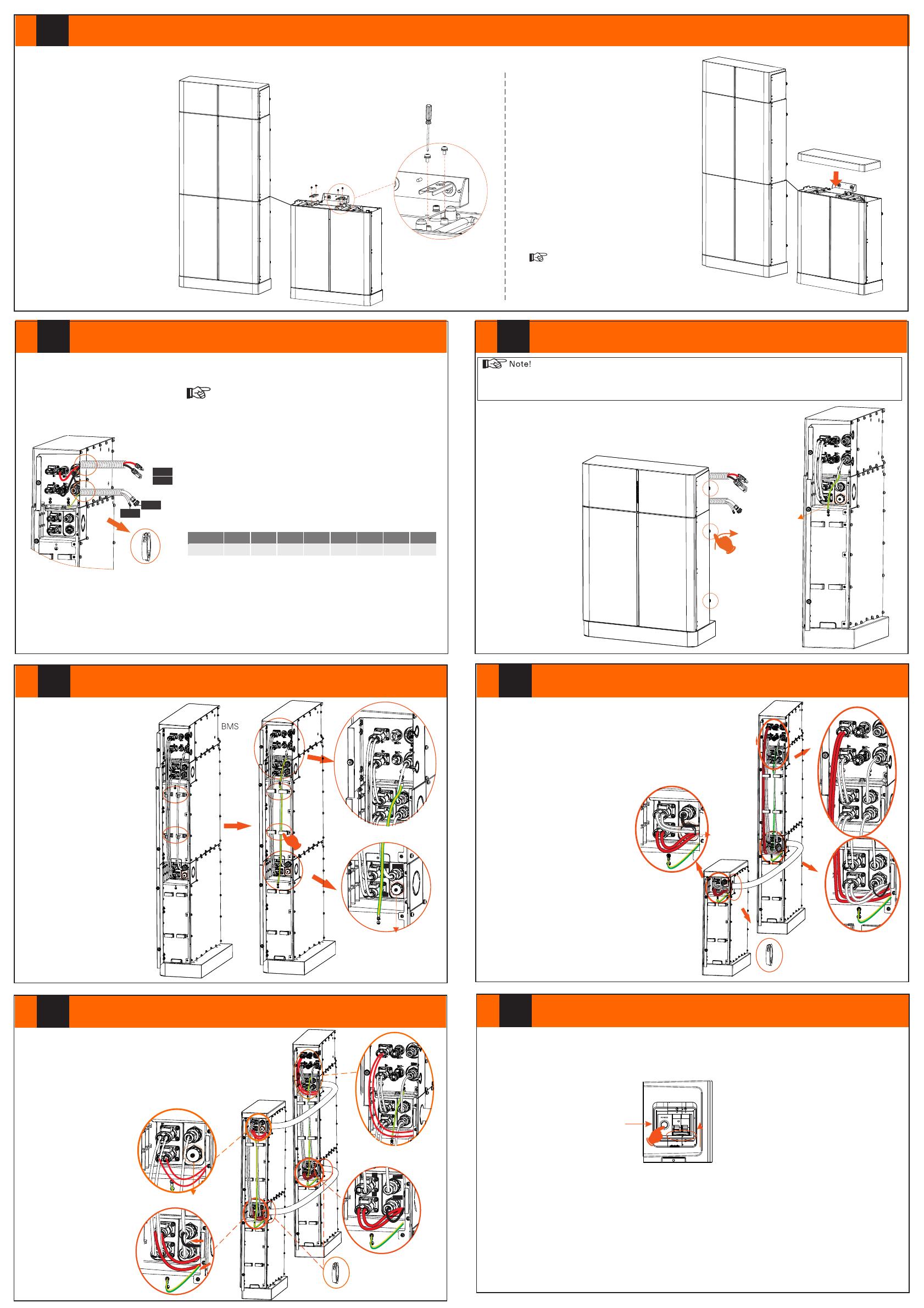
8Connecting Cables to Two Battery Modules 9Connecting Cables to Three Battery Modules
Installation Steps for BMS * 1 + Battery * 3
5
As for the installation steps for “Left: BMS + BAT x 2, Right: BAT x 1”, please refer to the installation steps for “BMS x 1 + Battery x 1”.
After finishing the installation of BMS, two bases and three batteries, please follow the steps below to install the Cover.
Step 1: Secure supporting brackets
using screws (4 X M4*10, torque:
0.8-1.2 N·m).
4 X M4*10
2 X Supporting Bracket
Torque: 0.8-1.2 N·m
Step 2: Put the cover on the battery.
Note!
The above steps also apply to place 4
battery modules.
Before connecting to inverter, please install PV terminal to the
power cables according to the following steps.
Step 1: Strip the cable (A/B: 2 m) to 15 mm;
Step 2: Insert the stripped cable up to the stop (negative cable
for DC plug (-) and positive cable for DC socket (+) are live).
Hold the housing on the screw connection;
Step 3: Press down the spring clamp until it clicks audibly into
place, and then the fine wire strands in the chamber can be seen
in the chamber;
Step 4: Tighten the screw connection (Torque: 0.8-1.2 N·m).
BMS to Battery1:
B+ to B+ (C: 1200 mm)
B- to B- (A1: 690 mm)
COMM to COM1
(E: 200 mm)
Ensure that both ends of the cables are connected to the correct
connector, which are on the right side of the BMS and battery module.
BMS and battery module are required to connect ground wire (F: 150
mm). BMS
Waterproof
cap
BMS to Battery1: B+ to B+
(C: 120 mm); COMM to
COM1 ( : 200 mm)E
Battery1 to Battery2: B- to
B+ (A1: 6 0 mm); COM2 to 9
COM1 (B1: 600 mm)
Battery2 to BMS: B- to B-
(A1: 690 mm)
B+
B-
COMM1
Waterproof
Cap
Battery1
Battery2
Ground wires are required to be
connected. (C1 (450 mm) is
used for connecting two battery
modules.) BMS to Battery1:
B+ to B+ (C: 120 mm); COMM to
COM1 (E: 200 mm);
BMS to Battery3:
B- to B- (B3: 1.8 m); Get the cables
through corrugate pipe.
Battery1 to Battery2:
B- to B+ (A1: 690 mm); COM2 to
COM1 (B1: 600 mm)
Battery2 to Battery3:
B- to B+ (A2: 1.2 m); COM2 to
COM1 (B2: 1.2 m); Get the cables
through corrugate pipe.
Ground wires are required to be connected. (C2: 1200
mm is used for connecting battery modules.)
Waterproof
Cap
Battery3
BMS
Battery1
Battery2
BMS
BM S
The two ends of the corrugated
pipe need to be protected with
guard rings.
BMS to Battery1:
B+ to B+ (C: 120 mm); COMM to COM1 (E:200 mm);
Battery1 to Battery2:
B- to B+ (A1: 690 mm); COM2 to COM1 (B1: 600 mm);
Battery2 to Battery3:
B- to B+ (A2: 1.2 m); COM2 to COM1 (B2: 1.2 m);
Battery3 to Battery4:
B- to B+ (A1: 690 mm) and COM2 to COM1 (B2: 1.2 m),
get the cables through corrugate pipe;
Ground wires are required
to be connected.
The two ends of the corrugated pipe need
to be protected with guard rings.
31
Battery3
Battery4
Battery1
Battery2
COM1
B+
COM2
B-
BMS
BMS
BMS
Waterproof cap
Battery4 to BMS:
B- to B- (A3: 1.2 m), get the cable
through corrugate pipe.
The two ends of the
corrugated pipe need to
be protected with guard
rings.
Once all battery modules are installed, follow these steps to start the system:
1) Open the cover of the BMS;
2) Move the circuit breaker switch to “ON”;
3) Press and hold the POWER button for more than 1s to start the T-BAT system; and
4) Turn on the AC breaker of inverter.
Black Start: Press the POWER button and hold it for 20 sec; release the button after the four SOC indicators flash blue alternately.
But, we do not recommend the use of Black Start as it may cause the port to be charged, resulting in an electric shock.
If the batteries have not been used for more than 9 months, these batteries must be charged to at least SOC 50 % each time.
For the first installation, the interval among manufacture dates of battery modules shall not exceed 3 months.
If one of the batteries is replaced, the SOC of the battery after replacement shall be consistent with those of batteries that have not
been replaced, with the maximum difference of between -5% and 5%.
If users want to increase their battery system capacity, please ensure that the SOC of the existing system capacity is about 40%.
The manufacture date of the new battery shall not exceed 6 months; in case of exceeding 6 months, please charge the new battery
to around 40%.
Cable Connection Steps:
Ø
The connector connecting to inverter from BMS is delivered with
the inverter, for details, please refer to the inverter's User Manual.
Note!
Connecting the BMS Communication Cable
Ø
It is required for the BMS to communicate with the inverter for
proper operation.
Note that the BMS communication cable is shielded with steel
tubes.
The wire order of the communication cable is the same as the
BMS communication cable.
Sequence 23 41
BMS / / BMS_H
GND
567 8
BMS_L /A1 B1
614.00892.00
+
-
To Inverter
BAT-
BAT+
GND
BMS
BMS +
-


