Tektronix TDS 510A Reference

Type
Reference

This manual is also suitable for

Tektronix TDS 510A is a powerful digital oscilloscope designed to meet the needs of engineers and technicians in a wide range of applications. With its 1 GHz bandwidth, 2 GS/s sample rate, and large 10.4-inch display, the TDS 510A can capture and analyze even the most complex signals with ease. It offers a variety of features to help you get the most out of your measurements, including:

  • Automatic measurements: The TDS 510A can automatically measure a variety of parameters, including frequency, period, rise time, and fall time.
  • Cursors: Cursors can be used to measure the time and voltage difference between two points on a waveform.
Reference
TDS 420A, TDS 430A, TDS 460A & TDS 510A
Digitizing Oscilloscopes
070-9758-00
To Save a Hardcopy to the File System:
Press SAVE/RECALL WAVEFORM, and use the menu buttons to save a waveform to a file or
recall it from a file.
Press SAVE/RECALL SETUP, and use the menu buttons to save a setup to a file or recall it from
a file.
Press File Utilities in the Save/Recall Waveform, Save/Recall Setup, or Hardcopy menus to access
utilities that create directories, copy files, and do other operations in the oscilloscope file system.
Press Format in the main menu, and select a
hardcopy format from the side menu.
Press SHIFT, and then press HARDCOPY.
12
Press HARDCOPY anytime to save a copy
of the current screen to a unique file in the
oscilloscope file system.
Press Port in the main menu, press File in the
side menu, and then press CLEAR MENU.
34
To Perform Other File System Operations:
Copyright Tektronix, Inc. Printed in U.S.A.
Disk Drive
Device Under
Test
To Display a Waveform:
Press
AUTOSET.
Adjust VERTICAL and HORIZONTAL
POSITION and SCALE as desired.
Press
CH 1 button.
1234
Attach a probe to CH 1
and hook it up to your signal.
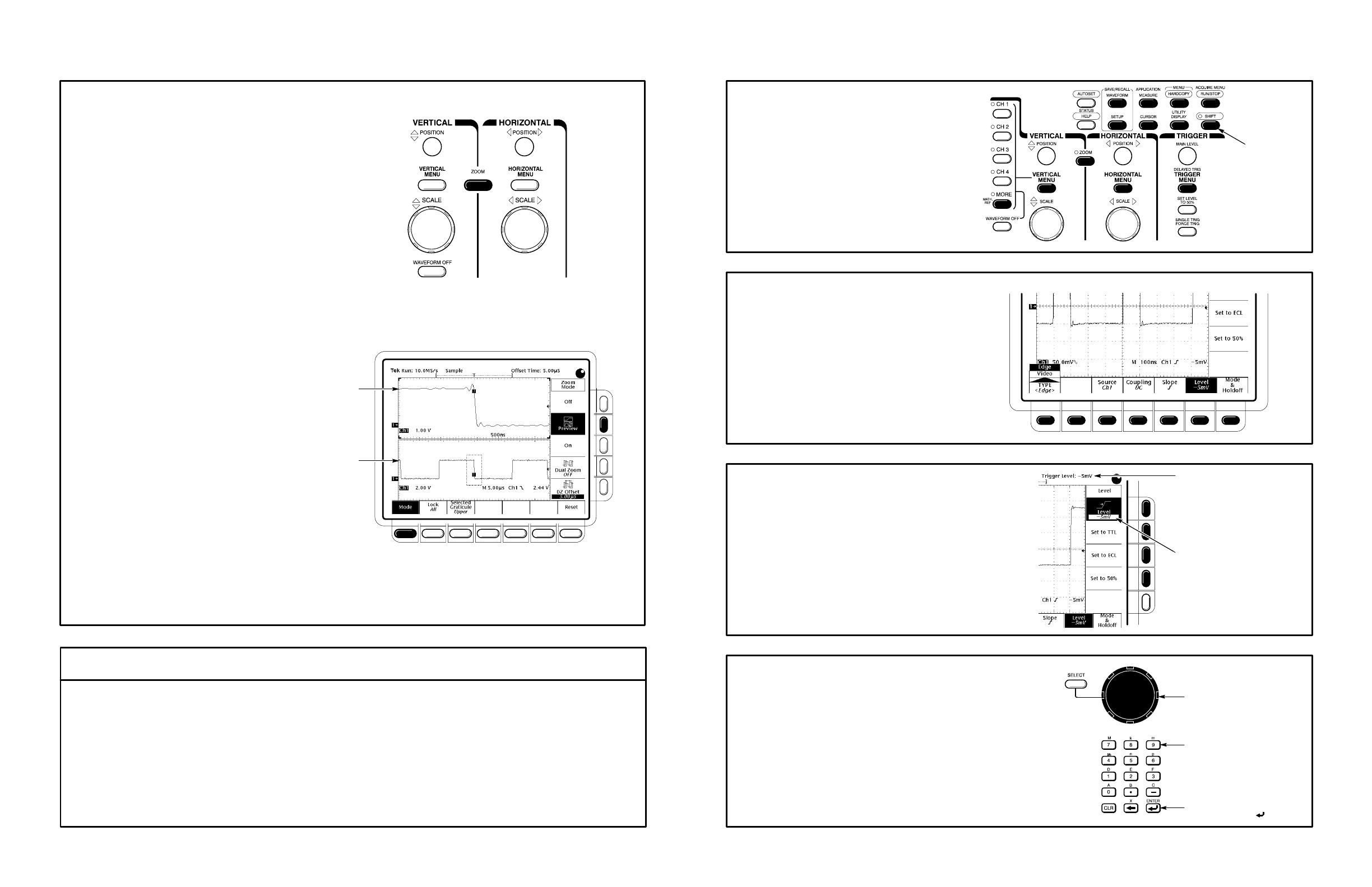
To Zoom or Zoom Preview a Waveform:
1
2
Press ZOOM.
TDS 400A only: press Mode in the main
menu. Then press Preview in the side menu
to turn on Dual Window Zoom.
TDS 400A only: use the Selected Graticule
menu to select the upper or lower waveform.
3
Upper graticule zooms the boxed area
on the selected waveform.
Lower graticule displays the selected waveform
unzoomed with the zoomed area in box.
Press Lock (TDS 400A) or Horizontal Lock (TDS 510A) to choose which waveform group to zoom horizontally.
TDS 400A only: press Selected Graticule, and use the menu buttons to direct the scale and position knobs to
the upper (zoomed waveforms) or lower (acquisition waveforms) graticule.
Press Reset Zoom Factors (TDS 510A) or Reset and use the menu buttons (TDS 400A) to reset zoom Factors.
To Perform Other Zoom Operations:
To Set Up Using a Menu:
Select an item from the main (bottom) menu.
Press any of the front panel menu buttons.
Select any displayed item from the side menu.
1
2
3
Use SHIFT
Button for
Alternate (Blue)
Menus
Turn the Vertical and Horizontal SCALE and POSITION knobs to adjust the scale and position factors of
the acquisition or the zoomed waveforms.
Adjustable Menu Item Value
Readout Indicates Value That
You Can Adjust With the
General Purpose Knob
Adjust menu item values using the general purpose
knob or by entering numbers on the keypad.
General Purpose Knob
Keypad (TDS 510A)
End Your Entry by
Pressing ENTER ( )
4
Use the vertical and horizontal knobs to adjust
the waveform.
4
TDS 400A
Automated Measurement Selections
Select
Measurement
Period
Frequency
Positive
Width
Negative
Width
—more—
1 of 7
Rise Time
Fall Time
Positive
Duty Cycle
Negative
Duty Cycle
—more—
2 of 7
Delay
Phase
Burst Width
—more—
3 of 7
High
Low
Max
Min
—more—
4 of 7
Pk–Pk
Amplitude
Positive
Overshoot
Negative
Overshoot
—more—
5 of 7
Mean
Cycle Mean
RMS
Cycle RMS
—more—
6 of 7
Area
Cycle Area
To Take Measurements Automatically:
Press Select Measrmnt or Snapshot
in main menu.
Press the MEASURE button.
Select up to four
measurements.
Press the CLEAR MENU button to move
measurement readouts away from graticule.
12
3
4
To
1 of 7
—more—
7 of 7
Incoming
Signal
Waveform
Drawn on CRT
Samples Acquired
for Each Waveform
Data Point Interval
Displayed
Data Point
Acquisition Mode
Processes
Samples
How the Acquisition Modes Work:
Use to reduce apparent noise
in a repetitive signal.
Use for fastest acquisition rate.
Sample is the default mode.
Use to reveal aliasing and for
glitch detection.
Peak Detect provides the
benefits of enveloping with
speed of single acquisition.
Use to reduce apparent noise.
Hi Res provides the benefits
of averaging with the speed of
single acquisition.
Use to reveal the noise band
around the signal.
Single
Waveform
Acquisition
Multiple
Waveform
Acquisitions
Sample
Peak Detect
Hi Res
Envelope
Average
Uses first sample in interval
Uses highest and lowest
samples in interval
Calculates average of
samples in interval
Uses highest and lowest
samples over many acquisitions
Calculates average value over
many acquisitions
To Take Measurements With Cursors:
Move cursor with the general purpose knob.
Press SELECT to switch between cursors.
Press SHIFT to speed up/slow down cursor movement.
Select from the side menu.
Press CURSOR button.
Press Function in the main menu.
1
2
3
4
Measures Voltage
(Vertical Units) at Time
Measures Time
Measures Voltage
(Vertical Units)
Difference Between Cursors
@ Position of Active Cursor Relative
to Ground (Horizontal Bars) or
Trigger (Vertical Bars)
Press Mode in main menu.
To Choose an Acquisition Mode:
12
3
Press SHIFT, and then press
ACQUIRE MENU.
From side menu, select an
acquisition mode that will serve
your application.
To Use the External Clock (TDS 400A):
Press Clock in main menu,
and then press External in side menu.
12
Press HORIZONTAL MENU.
Now turn any knob or press any button and
read a description of it on the display.
Press the HELP button again to exit help.
Press the HELP button.
To Display Help On Screen:
1
2
Press the SHIFT button to change the rate that the
VERTICAL and HORIZONTAL POSITION knobs
and the general purpose knob make adjustments.
To Speed Up Knob Adjustments:
To Select a Trigger:
Set TRIGGER MAIN LEVEL.
Press TRIGGER MENU.
Select a trigger type or parameter from
the main menu.
1
2
3
Press to Display
the Pop-Up
Menus
A Pop-Up Selection
Changes the Other
Main Menu Items
Press Again to
Make a
Selection
Title of the
Side Menu
Arrow Shows
the Trigger Level
Removes the
Menus From
the Screen
“T” Shows the
Trigger Position
Indicates a
Pop-Up Menu
This Symbol
TYPE <Pulse> (TDS 510A)
CLASS
Glitch
CLASS
Runt
TYPE Video
(Optional on some
models)
Glitch (Filter) Level
Thresholds
Polarity & Width
Polarity
Source
Source
CLASS
Width
Trigger When Level Polarity Source
Within
Limits
Out of
Limits
Set Lower and
Upper Limits
Select any one of
Ch 1 thru Ch 4
Positive
Negative
Width
Accept
Glitch
Reject
Glitch
OFF
ON
Runt
Upper
Runt
Lower
Select any one of
Ch 1 thru Ch 4
Select any one of
Ch 1 thru Ch 4
Select any one of
Ch 1 thru Ch 4
Source
Negative Sync
Positive Sync
2
Qualification by width
NTSC
PAL
HDTV
(TDS 510A)
FlexFmt
(TDS 510A)
Standard Field/Line
Set video field,
line number,
and, on
TDS 400A, time
Sync Polarity
Negative
Positive
Either
Negative
Positive
Either
Level Level
Set level or select
preset level based
on TTL or ECL logic
Set level or select
preset level based
on TTL or ECL logic
Set levels or select
preset levels based
on TTL or ECL logic
Define levels High,
Low, or Don’t Care
for Ch 1 thru Ch 3
TYPE <Logic> (TDS 510A)
CLASS
State
Trigger When Set Thresholds Define Logic Define Inputs
AND
OR
NAND
NOR
Select edge for the
clock (always Ch 4)
Set a threshold
level for each of
the pattern
channels, Ch 1
thru Ch 3, and
the clock, Ch 4
Goes FALSE
Goes TRUE
Trigger Selections
TYPE Edge
Level Slope Source
CLASS
Pattern
Set Thresholds Define Logic Define InputsTrigger When
Coupling
Goes FALSE
Set a threshold
level for each of
Ch 1 thru Ch 4
Select any one of
Ch 1 thru Ch 4,
Line, or Auxiliary
Define levels High,
Low, or Don’t Care
for Ch 1 thru Ch 4
Positive
Negative
AND
OR
NAND
NOR
DC
AC
HF
Reject
LF
Reject
Noise Rej (DC
Low Sensitivity)
Goes TRUE
TRUE for
less than
1
TRUE for
more than
1
1
Qualification by time
Level
Set level or select
preset level based
on TTL or ECL logic
SECAM
Custom
(TDS 400A)
  • Page 1 1
  • Page 2 2
  • Page 3 3
  • Page 4 4
  • Page 5 5
  • Page 6 6

Tektronix TDS 510A Reference

Type
Reference
This manual is also suitable for

Tektronix TDS 510A is a powerful digital oscilloscope designed to meet the needs of engineers and technicians in a wide range of applications. With its 1 GHz bandwidth, 2 GS/s sample rate, and large 10.4-inch display, the TDS 510A can capture and analyze even the most complex signals with ease. It offers a variety of features to help you get the most out of your measurements, including:

  • Automatic measurements: The TDS 510A can automatically measure a variety of parameters, including frequency, period, rise time, and fall time.
  • Cursors: Cursors can be used to measure the time and voltage difference between two points on a waveform.

Ask a question and I''ll find the answer in the document

Finding information in a document is now easier with AI