Greenlee DM-810A, DM-820A, DM-830A, DML-430A Multimeters User manual
- Category
- Measuring, testing & control
- Type
- User manual

INSTRUCTION MANUAL
MANUAL DE INSTRUCCIONES
MANUEL D’INSTRUCTIONS
Read and understand all of the instructions and safety information in this
manual before operating or servicing this tool.
Lea y entienda todas las instrucciones y la información sobre seguridad
que aparecen en este manual, antes de manejar estas herramientas o
darles mantenimiento.
Lire attentivement et bien comprendre toutes les instructions et les
informations sur la sécurité de ce manuel avant d’utiliser ou de procéder à
l’entretien de cet outil.
Register this product at www.greenlee.com / Registre este producto en www.greenlee.com
Enregistrez votre produit en ligne, www.greenlee.com
DM-810A • DM-820A
DM-830A • DML-430A
Digital Multimeters
Multímetros digitales
Multimètres
numériques
52047799 REV 4 © 2016 Greenlee Textron Inc. 6/16

2
Description
The Greenlee DM-810A, DM-820A, DM-830A, and DML-430A Digital Multimeters are hand-held
testing devices with the following measurement capabilities: AC and DC voltage, AC and DC current,
frequency, resistance, capacitance, and duty cycle of logic level signals. They also check diodes and
verify continuity. All meters feature true RMS AC measurements, a relative zero mode, data hold mode,
and an intelligent automatic power off. An optional optically isolated computer interface with software
facilitates the recording of readings from the meter to a computer.
Other specialized capabilities and functions common to all meters include:
• Dual display shows two measurements, such as AC voltage and frequency, at the same time.
• Backlighted LCD for reading in dim conditions.
• Beep-Jack™ audible warning alerts the user with a beep and an error message on the LCD if the
test lead is plugged into the mA/µA or A input terminal while the selector switch is not in the mA/µA
or A position.
• Bar graph display, which responds more quickly than the numeric display — useful for detecting
faulty contacts, potentiometer clicks, and signal spikes.
The DM-820A, DM-830A, and DML-430A multimeters have the following additional capabilities:
temperature (K-type thermocouples only); conductance; a crest function, which captures voltage or
current signal peaks; and a recording function, which stores the maximum, minimum, and difference
(maximum-minimum) input readings. The DM-820A and DM-830A record function can also calculate
the average reading. These two models also have non-contact and single-probe voltage detection.
The DM-830A and the DML-430A multimeters have an AutoCheck™ function for automatic selection
of AC voltage, DC voltage, and resistance with low input impedance to mask “ghost” voltages. Both
multimeters feature a T1-T2 function, which can measure and display two temperatures and calculate
the difference. They also feature AC + DC true RMS measurement capability. The DM-830A has a dBm
function with selectable reference impedances. The DML-430A has the capability to store data.
Safety
Safety is essential in the use and maintenance of Greenlee tools and equipment. This instruction
manual and any markings on the tool provide information for avoiding hazards and unsafe practices
related to the use of this tool. Observe all of the safety information provided.
Purpose of This Manual
This instruction manual is intended to familiarize all personnel with the safe operation and maintenance
procedures for the Greenlee DM-810A, DM-820A, DM-830A, and DML-430A Digital Multimeters.
Keep this manual available to all personnel. Replacement manuals are available upon request at no
charge at www.greenlee.com.
Do not discard this product or throw away!
For recycling information, go to www.greenlee.com.

DM-810A • DM-820A • DM-830A • DML-430A
3
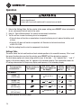
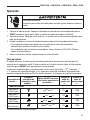
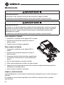
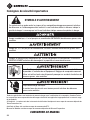
SAFETY ALERT SYMBOL
This symbol is used to call your attention to hazards or unsafe practices which could result in an
injury or property damage. The signal word, defined below, indicates the severity of the hazard.
The message after the signal word provides information for preventing or avoiding the hazard.
Immediate hazards which, if not avoided, WILL result in severe injury or death.
Hazards which, if not avoided, COULD result in severe injury or death.
Hazards or unsafe practices which, if not avoided, MAY result in injury or property damage.
Read and understand this material before operating or servicing this
equipment. Failure to understand how to safely operate this tool could result in
an accident causing serious injury or death.
Electric shock hazard:
Contact with live circuits could result in severe injury or death.
Important Safety Information
All specifications are nominal and may change as design improvements occur. Greenlee Textron Inc. shall not be liable
for damages resulting from misapplication or misuse of its products.
® Registered: The color green for electrical test instruments is a registered trademark of Textron Innovations Inc.
AutoCheck and Beep-Jack are trademarks of BTC.
Microsoft and Windows are registered trademarks of Microsoft Corporation.
KEEP THIS MANUAL

4
Important Safety Information
Electric shock and fire hazard:
• Do not expose this unit to rain or moisture.
• Do not use the unit if it is wet or damaged.
• Only use the test leads provided with the equipment or UL Listed Probe Assembly with same rating
or better.
• Inspect the test leads or accessory before use. They must be clean and dry, and the insulation
must be in good condition. Do not use the test lead if the contrasting inner layer of insulation is
visible.
• Use this unit for the manufacturer’s intended purpose only, as described in this manual. Any other
use can impair the protection provided by the unit.
Failure to observe these warnings could result in severe injury or death.
Electric shock hazard:
• Do not apply more than the rated voltage between any two input terminals, or between any input
terminal and earth ground.
• Do not contact the test lead tips or any uninsulated portion of the accessory.
Failure to observe these warnings could result in severe injury or death.
Electric shock hazard:
• Do not operate with the case open.
• Before opening the case, remove the test leads from the circuit and shut off the unit.
Failure to observe these warnings could result in severe injury or death.
Electric shock hazard:
The fuses are an integral part of the overvoltage protection. When fuse replacement is necessary,
refer to “Specifications” for the correct type, size, and capacity. Using any other type of fuse will void
the overvoltage protection rating of the unit.
Failure to observe this warning could result in severe injury or death.

DM-810A • DM-820A • DM-830A • DML-430A
5
Important Safety Information
Electric shock hazard:
• Unless measuring voltage, current, or frequency, shut off and lock out power. Make sure that all
capacitors are discharged. Voltage must not be present.
• Set the selector and connect the test leads so that they correspond to the intended measurement.
Incorrect settings or connections can result in a blown fuse.
• Using this unit near equipment that generates electromagnetic interference can result in unstable
or inaccurate readings.
Failure to observe these warnings could result in severe injury or death.
Electric shock hazard:
Do not change the measurement function while the test leads are connected to a component or
circuit.
Failure to observe this precaution may result in injury and can damage the unit.
Electric shock hazard:
Do not use the tester to measure voltages in circuits that could be damaged or activated by the
AutoCheck™ mode’s low input impedance (approximately 3.0 kΩ and 150 pF).
Failure to observe this precaution may result in injury and can damage the unit.
Electric shock hazard:
• Do not attempt to repair this unit. It contains no user-serviceable parts.
• Do not expose the unit to extremes in temperature or high humidity. Refer to “Specifications.”
Failure to observe these precautions may result in injury and can damage the unit.

6
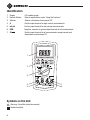
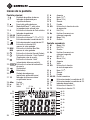
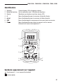
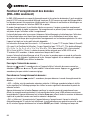
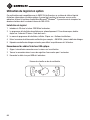
Identification
1. Display LCD and bar graph
2. Feature Buttons Refer to explanations under “Using the Features”
3. Selector Selects a function or turns power OFF
4. A Positive input terminal for high current measurements
5. mA µA Positive input terminal for low current measurements
6. COM Negative, common, or ground input terminal for all measurements
7. ΩV Positive input terminal for all measurements except current and
temperature measurement T2
5
3
2
1
4
6
7
Symbols on the Unit
Warning—Read the instruction manual
Double insulation

DM-810A • DM-820A • DM-830A • DML-430A
7
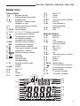
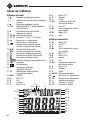
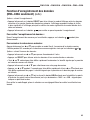
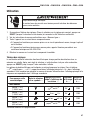
Primary Display
8.
Bar graph element
9. – Polarity indicator for bar graph
10. Bar graph scale
11. LoZ AutoCheck™ mode; low input
impedance is active.
12. ∆ Relative zero function is enabled.
13. – Polarity indicator
14. 8.8.8.8 Numeric display
15. T1-T2 T1, T2, or T1-T2 function is enabled.
16. AC measurement is selected.
17. DC measurement is selected.
18. AVG AVG function is enabled;
recorded value is displayed.
19. MAX- Max-Min function is enabled;
MIN recorded value is displayed.
20. Record function is enabled.
21. Crest capture function is enabled.
22. Hold function is selected.
23. Automatic ranging is enabled.
24. Continuity
25. Low battery
26. } Overload symbol
(bar graph display)
27. 10 Bar graph maximum range
indicator
28. dBm Decibel
29. m Milli (10
-3
)
30. V Volt
31. A Ampere
32. n Nano (10
-9
)
33. µ Micro (10
-6
)
34. S Siemen
35. F Farad
36. D% Duty cycle function is enabled.
37. k Kilo (10
3
)
38. Hz Hertz (frequency in
cycles per second)
39. M Mega (10
6
)
40. Ω Ohm
Secondary Display
41. M Mega (10
6
)
42. k Kilo (10
3
)
43. Ω Ohm
44. Hz Hertz (frequency in
cycles per second)
45. m Milli (10
-3
)
46. µ Micro (10
-6
)
47. A Ampere
48. V Volt
49. D% Duty cycle function is enabled.
50. n Nano (10
-9
)
51. S Siemen
52. F Farad
53. 8.8.8.8 Numeric display
54. DC measurement is selected.
55. AC measurement is selected.
56. – Polarity indicator
57. T1 T1 function is enabled.
58. T2 T2 function is enabled.
Display Icons
23
20-22
19
18
16-17
15
13
12
11
10
8-9
14
49-52
45-48
41-44
39-40
37-38
36
32-35
28-31
26
27
2524
57-58
54-56 53

8
All Models
• Dual Digital Display: These meters can display two measurements, such as AC voltage and
frequency, at the same time. Display combinations are shown using large symbols to indicate the
measurement on the primary display and small, raised symbols to indicate the measurement on
the secondary display. For example, “VAC
Hz
” means the primary display contains the AC voltage
measurement, and the secondary display contains the frequency measurement.
• SELECT: Press momentarily to toggle between functions, or to toggle between AC and DC when
measuring current and millivolts.
• RANGE: Press once to enter the manual ranging mode. The icon will disappear from the
display. Press repeatedly to step through the ranges. Press and hold to return to the automatic
ranging mode.
Note: When using MAX-MIN, HOLD, or ∆ mode, pressing RANGE will cause the meter to exit that
mode.
• ∆: Finds the difference between two measurements. While taking a measurement, press ∆ to set the
display to zero. The ∆ icon will appear on the display. Take the second measurement. The value on
the display will be the difference between the two measurements. Press again to exit this mode.
• HOLD : Press momentarily to hold the present value on the display. Press again to exit this mode.
This feature does not affect the bar graph.
• : Press and hold until backlight illuminates. Press and hold again to turn off. The backlight
automatically turns off after approximately 30 seconds to extend battery life.
• Automatic Power Off: To extend battery life, the meter will shut itself off after approximately
30minutes of inactivity. To restore power, press either the SELECT, RANGE, ∆, or HOLD button
momentarily, or turn the selector to OFF and then back on. To disable this feature, press SELECT
while turning the meter on.
• Disabling the Beeper: Hold down the RANGE button while turning the meter on to temporarily
disable the beeper feature. Turn the selector to OFF and then back on to enable the beeper.
DM-820A, DM-830A, and DML-430A Only
• CREST : Press momentarily to activate the crest recording mode.The input value is measured
every 1 ms in this mode. and “MAX” will appear on the display. The LCD will display the maximum
crest value. Press repeatedly to select the desired display: maximum, minimum, or maximum–
minimum crest value. Press and hold to exit this mode.
The automatic power off feature is disabled when using this function.
Note: When using the CREST function, pressing RANGE will cause the meter to exit this mode.
• REC : Press momentarily to activate the MAX/MIN/AVG* recording mode. The input value is
measured every 50 ms in this mode. “MAX MIN” and “AVG”* will appear on the display. The LCD will
display the actual input value. The meter will beep whenever the maximum or minimum is updated.
Press repeatedly to select the deired display: maximum, minimum, maximum–minimum, average*,
or actual input. Press and hold to exit this mode.
*Average function is not available on DML-430A.
The automatic power off feature is disabled when using this function.
Using the Features

DM-810A • DM-820A • DM-830A • DML-430A
9
Using the Features (cont’d)
Note: When using the REC function, pressing RANGE will cause the meter to exit this mode.
DM-820A and DM-830A Only
• EF: Set the meter to any current or voltage function. Press and hold until the meter displays “EF” to
detect the electric field that surrounds current-carrying conductors. Signal strength is displayed as a
series of dashes on the display.
• Use the tester’s built-in antenna (located along the top, near the LCD) for tracing live circuits or
locating a break in a wire.
• For more precision, such as distinguishing between current-carrying and ground wires, connect a
test lead to the + input terminal and use it as a probe for direct contact verification of a signal.
DM-830A and DML-430A Only
• Low Impedance AutoCheck™ Mode: In this mode, the meter automatically selects the proper
measurement based on the input.
• If there is no input, “Auto” appears on the display.
• If the voltage is above approximately 1.5 volt DC or 3 volt AC up to the rated 1000 volts, voltage
is displayed.
• If both AC and DC voltages are present, the larger voltage is displayed.
• If no voltage is present and there is resistance less than 60 MΩ, resistance is displayed. If the
measured resistance is below the continuity threshold (between 20 Ω and 300 Ω), then the
continuity tone will sound.
This mode features low input impedance to mask stray or “ghost” voltage pickup. The input imped-
ance is approximately 3 kΩ at low voltage, increasing to approximately 460 kΩ at 1000 V.
The symbol “LoZ” indicates that the meter is in a low impedance mode. Do not use the AutoCheck™
mode on circuits that could be damaged or activated by such low input impedance. Instead use the
selector to select the high impedance AC or DC volt modes to minimize loading for such circuits.
Range-Lock and Function Feature: While in the AutoCheck™ mode, press the SELECT button
momentarily to lock the displayed function. Press the RANGE button momentarily to lock the dis-
played measurement range.
Energized Circuit Alert: If the resistance mode is locked in the AutoCheck™ mode and the leads
are placed across an energized circuit, the meter will emit an audible warning tone.
• T1-T2: Press momentarily to select the desired temperature display: T1, T2, T1
T2
, or T1-T2
T2
.
• dBm-Ω (DM-830A only): In dBm mode, press momentarily to select the reference impedance. Refer
to the “Specifications” section for the available values.
• Blue Feature Buttons (DML-430A only): Refer to the “Data Storage Function” section for an
explanation of these features.

10
AC Measurement
AC measurements are usually displayed as RMS (root mean square) values. The RMS value is equal to
the value of a DC waveform, which would deliver the same power if it replaced the time-varying wave-
form. Two AC measurement methods are average-responding RMS calibrated and true RMS-reading.
The average-responding RMS calibrated method takes the average value of the input signal after full
wave rectification, multiplies it by 1.11, and displays the result. This method is accurate if the input
signal is a pure sine wave.
The true RMS-reading method uses internal circuitry to read the true RMS value. This method is accu-
rate, within the specified crest factor limitations, whether the input signal is a pure sine wave, square
wave, triangle wave, half wave, or signal with harmonics. The ability to read true RMS provides much
more measurement versatility. The Greenlee DM-810A, DM-820A, DM-830A, and DML-430A are true
RMS meters.
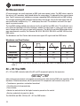
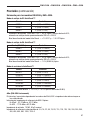
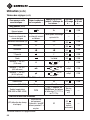
The Waveforms and Crest Factors table shows some typical AC signals and their RMS values.
Waveforms and Crest Factors
Waveform
RMS Value 100 100 100 100
Average Value 90 100 87 64
Crest Factor*
(x)
1.414 1 1.73 2
* The crest factor is the ratio of the peak value to the RMS value; it is represented by the Greek
letter x.
AC + DC True RMS
AC + DC true RMS calculates both of the AC and DC components given by the expression
when making measurements and responds accurately to the total effective RMS value regardless of the
waveform. Distorted waveforms with the presence of DC components and harmonics may cause:
• Transformers, generators, and motors to overheat
• Circuit breakers to trip prematurely
• Fuses to blow
• Neutrals to overheat due to the triplen harmonics present on the neutral
• Bus bars and electrical panels to vibrate
The DM-830A and DML-430A are AC + DC true RMS meters.

DM-810A • DM-820A • DM-830A • DML-430A
11
Data Storage Function (DML-430A only)
The DML-430A has data storage and retrieval capability. It can store up to 87,000 measurements in
single display mode or 43,000 measurements in dual display mode. The data can later be reviewed on
the multimeter’s display, or downloaded the data to a computer using the optional interface DMSC-9U.
When in the recording mode, the meter takes a measurement, assigns that measurement to the next
available memory location, and repeats the process. This continues until the memory is full or until the
user manually stops the recording process.
The time interval between measurements (sampling rate) is selected by the user. A shorter time interval
will provide information about short-term fluctuations, whereas a longer time interval will provide
information about general trends. The factory setting is the shortest time interval.
The time intervals are as follows: 0.05 seconds (0.1s for single T1/T2, Diode, and Ohms/nS; 0.5s for
Hz and Duty Cycle; 2s for Capacitance and dual screen T1/T2 and T1-T2), 0.1s, 0.5s, 1s, 2s, 3s, 4s, 5s,
10s, 15s, 30s, 60s,120s (two minutes), 180s (three minutes), 300s (5 minutes), and 600s (10 minutes).
The minimum total measurement time for the DML-430A is 72 minutes and 30 seconds; the maximum
is nearly 20 months.
When the sampling rate is 30s or greater, the meter will go to standby mode between measurements
to extend battery life. When the meter is in the standby mode, press SELECT momentarily to view the
display.
To set the measurement interval:
Press for 1 second or more and the meter will display the current measurement interval in seconds.
Press p or q to change the measurement interval. Press for 1 second or more to save the new
setting.
To start recording data:
Press the button for 1 second or more to start the data logging mode.
"LEFt" displays followed by the number of remaining memory in the logger. The number in the second-
ary display is the most significant digit, and the numbers in the primary display are the least significant
digits of the remaining memory points.
Momentarily press the Yes button to confirm a new logging session without erasing the formerly logged
ones (up to 999 sessions can be stored without overwriting previous sessions). Press the Erase button
momentarily to erase all of the sessions and start from the first session with full memory.
"Strt" will display on the primary screen and then the logger will start recording. When a sampling
speed of 30s or longer is selected, the meter will enter a power down mode after 4.5 minutes. Press
the SELECT button momentarily to resume real time display.
Options —during recording:
• Press the SELECT button momentarily to toggle the display mode between measuring data and
logged data item number. The secondary display contains the most significant number and the
primary display contains the least significant numbers of the logged data item number.
• Press the button momentarily to pause/resume logging.

12
Data Storage Function (DML-430A only) (cont’d)
To stop recording data:
While the meter is logging data, press the button for more than 1 second.
To review stored data:
Press p and q momentarily to enter Recall mode. The last session number displays for 0.5 seconds
and then displays the last logged data item as well the and annunciators.
Options —while reviewing data:
• Press p or q momentarily to step through the data.
• Press SELECT to toggle between the data and the logged data item number.
• Press and hold p or q to quickly scan through the data. Tone indicates that the first or last mea-
surement is displayed.
• Press p and q momentarily to select another session page.
• Press p and q for 1 second for fast scrolling, and hold either p or q to quickly scroll through the
pages. Tone indicates that the first or last session page is displayed.
• Press p or q momentarily while holding down the HOLD button to scan through the turning points
(the alternating high and low points) or the data set. “MAX” or “MIN” will flash to indicate a high or
low point.
To exit Recall mode, rotate the selector to a different setting or turn the meter off.

DM-810A • DM-820A • DM-830A • DML-430A
13
Using the Optional Software
These meters are compatible with Greenlee DMSC-9U, an optically isolated computer interface cable
and software. It allows measurements to be logged to a personal computer using the Microsoft
®
Windows
®
operating system. It also allows retrieval of data stored in the internal memory of
DML-430A.
Installing the Software
1. Insert the CD into the computer’s CDROM drive.
2. The installation program should launch automatically. If it does not, double click on the CD icon in
“My Computer.”
3. The installation program menu will appear. Click on “Software Installation.”
4. Type your meter’s catalog number (for example, “DM-820A”) in the dialog box.
5. Complete the remaining dialog boxes according to user preferences.
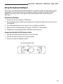
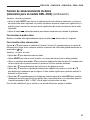
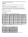
Connecting the Optical USB Interface Cable
1. Align the key of the connector with the key slot on the meter.
2. Twist the connector clockwise until it locks into place.
3. Connect the cable to a USB port of the PC.
Key slot on back of meter

14
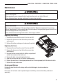
Operation
Electric shock hazard:
Contact with live circuits could result in severe injury or death.
1. Refer to the Settings Table. Set the selector to the proper setting, press SELECT (when instructed to
do so), and connect the test leads to the meter.
2. Refer to “Typical Measurements” for specific measurement instructions.
3. Test the unit on a known functioning circuit or component.
• If the unit does not function as expected on a known functioning circuit, replace the battery and/
or fuses.
• If the unit still does not function as expected, call Greenlee for technical assistance
at 800-435-0786.
4. Take the reading from the circuit or component to be tested.
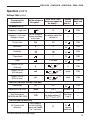
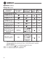
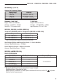
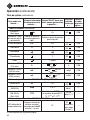
Settings Table
The meter stores the last used function of each selector position in its nonvolatile memory. If this is not
the correct function when you turn the selector, press SELECT until the desired icon appears.
The dual display options are shown along with the icons. In the table, “~V
Hz
” indicates that “~” and “V”
appear in the primary display, and “Hz” appears in the secondary display. This combination shows the
AC voltage measurement in the primary display and frequency in the secondary display.
To measure this
characteristic …
Set the selector to
this symbol…
Press SELECT until
these icons appear on
the display …
Connect
the red
lead to…
Connect the
black lead
to …
All Models
Voltage—AC
(1000 V max)
V
Hz
or Hz
~V
ΩV
COM
Voltage—DC
(1000 V max)
V or V
~V
ΩV
COM
Voltage—DC
(600 mV max)
mV or mV
~mV
ΩV
COM
Voltage—AC
(600 mV max)
mV
Hz
or Hz
~mV
ΩV
COM
This table continues on the next page.

DM-810A • DM-820A • DM-830A • DML-430A
15
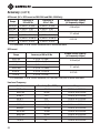
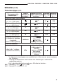
Settings Table (cont’d)
To measure this
characteristic …
Set the selector to
this symbol…
Press SELECT until
these icons appear on
the display …
Connect
the red
lead to…
Connect the
black lead
to …
All Models (cont’d)
*Frequency—Logic Level
Hz
Hz
ΩV
COM
Frequency—Line Level
Voltage or Current
Set for voltage or
current according
to this table.
Any display option that
includes Hz
— —
% Duty Cycle D% D%
ΩV
COM
Resistance Ω Ω
ΩV
COM
Continuity
ΩV
COM
**Capacitance F
ΩV
COM
Diode V and diod
ΩV
COM
Current—AC/DC
(10 A max)
A
A, A
~A
or A
Hz
A COM
Current—AC/DC
(600 mA max)
mA
mA, mA
~mA
or mA
Hz
mAµA COM
Current—AC/DC
(6000 µA max)
µA
µA, µA
~µA
or µA
Hz
mAµA COM
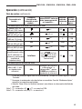
DM-820A, DM-830A, and DML-430A Only
Conductance nS nS
ΩV
COM
Temperature (DM-820A) Temp °C or °F See Note 1 —
Dual Temperature
(DM-830A and DML-430A)
T1T2
°C or °F (press RANGE
for display options T1,
T2, T1
T2
or T1-T2
T2
)
See Notes
1 and 2
—
DM-820A and DM-830A Only
†EF (electric field
detection)
Any voltage or
current function;
press and hold EF
for 1 s or more
EF
ΩV
(contact
mode only)
—
This table continues on the next page.
Operation (cont’d)

16
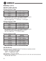
Settings Table (cont’d)
To measure this
characteristic …
Set the selector to
this symbol…
Press SELECT until
these icons appear
on the display …
Connect
the red
lead to…
Connect the
black lead
to …
DM-830A and DML-430A Only
Voltage—AC + DC
TrueRMS (1000 V max)
V
~V
ΩV
COM
Voltage—AC + DC
TrueRMS (600 mV max)
mV
~mV
ΩV
COM
Current—AC + DC
TrueRMS (10 A max)
A
A
~A
A COM
Current—AC + DC
TrueRMS (600 mA max)
mA
mA
~mA
mAµA COM
Current—AC + DC
TrueRMS (6000 µA max)
µA
µA
~µA
mAµA COM
†Auto select AC volts,
DC volts, resistance, and
continuity (low impedance
measurement)
AutoCheck
LoZ and
(LoZ with V,
V or Ω when
using Feature Lock)
ΩV
COM
DM-830A Only
dBm (0 dB = 1 mW in
reference impedance)
dBm
Reference
impedance and dBm
for 1 s, then dBm
Hz
(press RANGE to
change reference
impedance)
ΩV
COM
* Logic level frequency has a fixed sensitivity and is for digital signals. Refer to “Accuracy”.
** Discharge capacitor before measurement. Refer to “Typical Measurements” regarding
polarized capacitors.
† Refer to “Using the Features” for a detailed description of this mode.
Note 1: T1+ connects to ΩV and T1– connects to COM.
Note 2: T2+ connects to mAµA and T2– connects to A.
Operation (cont’d)

DM-810A • DM-820A • DM-830A • DML-430A
17
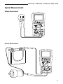
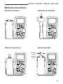
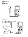
Typical Measurements
Voltage Measurement
Current Measurement

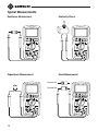
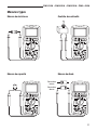
18
Typical Measurements
Continuity Check
Capacitance Measurement Diode Measurement
Forward Bias
Reverse Bias
Resistance Measurement

DM-810A • DM-820A • DM-830A • DML-430A
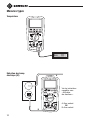
19
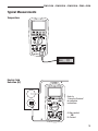
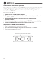
Typical Measurements
Temperature
Electric Field
Detection (EF)
Refer to
“Using the Features”
for complete
instructions.
A–Non-contact
OR
B–Contact
A
B

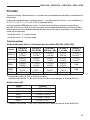
20
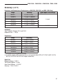
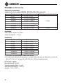
Accuracy
Refer to the “Specifications” section for operating conditions and temperature coefficient.
Accuracy is specified as follows: ± (a percentage of the reading + a fixed amount) at 23 °C ± 5 °C
(73.4 °F ± 9 °F), 0% to 75% relative humidity.
True RMS Readings: Voltage and current accuracies are specified from 10% to 100% of the range
unless otherwise specified. Frequency must be within the specified bandwidth for non-sinusoidal
waveforms. Crest factors are as follows:
• Crest factor < 3:1 at full scale
• Crest factor < 6:1 at half scale
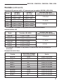
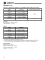
All Models
AC Voltage (AC + DC Voltage on DM-830A and DML-430A Only)
Range
Accuracy at
50 to 60 Hz
Accuracy at
40 to 500 Hz
Accuracy at
500Hz to 1 kHz
Accuracy at
1to 3 kHz
Accuracy at
3 to 20 kHz
60.00 mV
± (0.5% +
0.03mV)
± (0.8% +
0.04mV)
± (2.0% +
0.03mV)
± (2% +
0.03mV)
± (2% +
0.03mV)
(1)
600.0 mV
± (0.5% +
0.3mV)
± (0.8% +
0.4mV)
± (2.0% +
0.3mV)
± (2% +
0.3mV)
± (2% +
0.3mV)
(1)
9.999 V
± (0.5% +
0.003V)
± (1.0% +
0.004V)
± (1.0% +
0.004V)
± (3% +
0.004V)
3 dB
99.99 V
± (± (0.5% +
0.03 V)
± (1.0% +
0.04V)
± (1.0% +
0.04V)
± (3% +
0.04V)
3 dB
999.9 V ± (0.5% + 0.3 V) ± (2.0% + 0.4 V) ± (2.0% + 0.4 V) ± (3% + 0.4V) Unspecified
(1)
Specified from 30% to 100% of range
Input Impedance: 10 MΩ, 50 pF nominal (80 pF nominal for 600 mV range)
DC Voltage
Range Accuracy
60.00 mV ± (0.12% + 0.02 mV)
600.0 mV ± (0.06% + 0.2 mV)
9.999 V ± (0.08% + 0.002 V)
99.99 V ± (0.08% + 0.02 V)
999.9 V ± (0.08% + 0.2 V)
Input Impedance: 10 MΩ, 50 pF nominal (80 pF nominal for 600 mV range)
Page is loading ...
Page is loading ...
Page is loading ...
Page is loading ...
Page is loading ...
Page is loading ...
Page is loading ...
Page is loading ...
Page is loading ...
Page is loading ...
Page is loading ...
Page is loading ...
Page is loading ...
Page is loading ...
Page is loading ...
Page is loading ...
Page is loading ...
Page is loading ...
Page is loading ...
Page is loading ...
Page is loading ...
Page is loading ...
Page is loading ...
Page is loading ...
Page is loading ...
Page is loading ...
Page is loading ...
Page is loading ...
Page is loading ...
Page is loading ...
Page is loading ...
Page is loading ...
Page is loading ...
Page is loading ...
Page is loading ...
Page is loading ...
Page is loading ...
Page is loading ...
Page is loading ...
Page is loading ...
Page is loading ...
Page is loading ...
Page is loading ...
Page is loading ...
Page is loading ...
Page is loading ...
Page is loading ...
Page is loading ...
Page is loading ...
Page is loading ...
Page is loading ...
Page is loading ...
Page is loading ...
Page is loading ...
Page is loading ...
Page is loading ...
Page is loading ...
Page is loading ...
Page is loading ...
Page is loading ...
Page is loading ...
Page is loading ...
Page is loading ...
Page is loading ...
-
 1
1
-
 2
2
-
 3
3
-
 4
4
-
 5
5
-
 6
6
-
 7
7
-
 8
8
-
 9
9
-
 10
10
-
 11
11
-
 12
12
-
 13
13
-
 14
14
-
 15
15
-
 16
16
-
 17
17
-
 18
18
-
 19
19
-
 20
20
-
 21
21
-
 22
22
-
 23
23
-
 24
24
-
 25
25
-
 26
26
-
 27
27
-
 28
28
-
 29
29
-
 30
30
-
 31
31
-
 32
32
-
 33
33
-
 34
34
-
 35
35
-
 36
36
-
 37
37
-
 38
38
-
 39
39
-
 40
40
-
 41
41
-
 42
42
-
 43
43
-
 44
44
-
 45
45
-
 46
46
-
 47
47
-
 48
48
-
 49
49
-
 50
50
-
 51
51
-
 52
52
-
 53
53
-
 54
54
-
 55
55
-
 56
56
-
 57
57
-
 58
58
-
 59
59
-
 60
60
-
 61
61
-
 62
62
-
 63
63
-
 64
64
-
 65
65
-
 66
66
-
 67
67
-
 68
68
-
 69
69
-
 70
70
-
 71
71
-
 72
72
-
 73
73
-
 74
74
-
 75
75
-
 76
76
-
 77
77
-
 78
78
-
 79
79
-
 80
80
-
 81
81
-
 82
82
-
 83
83
-
 84
84


Greenlee DM-810A, DM-820A, DM-830A, DML-430A Multimeters User manual
- Category
- Measuring, testing & control
- Type
- User manual
Ask a question and I''ll find the answer in the document
Finding information in a document is now easier with AI
in other languages
Related papers
-
Greenlee DM-810A, DM-820A, DM-830A, DML-430A Multimeters User manual
-
-
-
Greenlee AM-6 User manual
-
-
Greenlee DM-25 User manual
-
-
-
-
Other documents
-
 Sperry instruments DM6200 Owner's manual
-
Sanwa PC720M User manual
-
Klein Tools CL700 Operating instructions
-
-
Gardner Bender GDT-3190 User guide
-
-
-
Fluke 116 Digital HVAC Multimeter User manual
-
Megger AVO410 User manual
-
