Magnetek 300M Series, Type MBE Electric Shoe Brakes Owner's manual
- Type
- Owner's manual
Magnetek 300M Series, Type MBE Electric Shoe Brakes are a versatile and reliable choice for a wide range of applications. These brakes are spring set and magnetically released, providing precise and dependable control. With a torque range from 5 to 30 inch-pounds, they are suitable for both light and heavy-duty applications.
The MBE Electric Shoe Brakes are designed for use in extreme temperatures and duty cycles, making them ideal for demanding industrial environments. They feature a self-adjustment mechanism that ensures consistent performance over the life of the brake linings, reducing maintenance requirements.


-
 1
1
-
 2
2
-
 3
3
-
 4
4
-
 5
5
-
 6
6
-
 7
7
-
 8
8
-
 9
9
-
 10
10
-
 11
11
-
 12
12
-
 13
13
-
 14
14
-
 15
15
-
 16
16
-
 17
17
-
 18
18
-
 19
19
-
 20
20
-
 21
21
-
 22
22
-
 23
23
-
 24
24
-
 25
25
-
 26
26
-
 27
27
-
 28
28
-
 29
29
-
 30
30
-
 31
31
-
 32
32
-
 33
33
-
 34
34


Magnetek 300M Series, Type MBE Electric Shoe Brakes Owner's manual
- Type
- Owner's manual
Magnetek 300M Series, Type MBE Electric Shoe Brakes are a versatile and reliable choice for a wide range of applications. These brakes are spring set and magnetically released, providing precise and dependable control. With a torque range from 5 to 30 inch-pounds, they are suitable for both light and heavy-duty applications.
The MBE Electric Shoe Brakes are designed for use in extreme temperatures and duty cycles, making them ideal for demanding industrial environments. They feature a self-adjustment mechanism that ensures consistent performance over the life of the brake linings, reducing maintenance requirements.
Ask a question and I''ll find the answer in the document
Finding information in a document is now easier with AI
Related papers
-
 Magnetek 300M Series, Type MBEM Electric Shoe Brakes and MBEP Brakes Owner's manual
-
 Magnetek MBT/E Electric Shoe Brakes Owner's manual
-
 Magnetek DT Heavy Duty Disc Brakes Owner's manual
-
Magnetek ST Electric Shoe Brakes Owner's manual
-
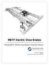
 Magnetek MBTF/E Electric Shoe Brakes Owner's manual
-
 Magnetek Plumbing Product MST E User manual
-
 Magnetek MBTF Electric Shoe Brakes Owner's manual
-
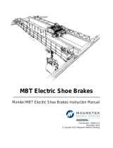 Magnetek MBT Electric Shoe Brakes Owner's manual
-
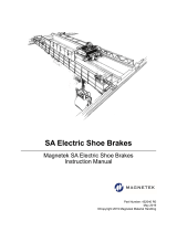 Magnetek SA Electric Shoe Brake Owner's manual
-
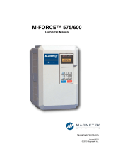 Magnetek M-FORCE® General Purpose (GP) 500 575/600 Drive Owner's manual


Other documents
-
Keating Pre 2000 User manual
-
Eaton GH505 Installation And Operation
-
Crosby HR-100 User manual
-
Kawasaki KVF 360 4×4 User manual
-
Polaris HawkEye User manual
-
Ransomes 836278 User manual
-
-
Suzuki UY125 User manual
-
DAELIM DAYSTAR VL125E User manual
-