Page is loading ...

Manual 2100-600
Page 1 of 38
Bard Manufacturing Company, Inc.
Bryan, Ohio 43506
Since 1914 . . . Moving ahead, just as planned.
Manual: 2100-600
Supersedes: NEW
File: Vol II Tab 14
Date: 08-21-13
Models:
Q24A2 Q30A2
Q36A2 Q42A2
Q48A2 Q60A2
Q-TEC SERIES
PACKAGED
AIR CONDITIONER
INSTALLATION
INSTRUCTIONS

Manual 2100-600
Page 2 of 38
CONTENTS
Figures
Figure 1 Unit Dimensions ...........................................7
Figure 2 Air Seal Under Unit ...................................... 8
Figure 3 Removal of Unit From Skid .......................... 8
Figure 4 Unit on Appliance Cart for Moving................ 9
Figure 5 Installation With Free Blow Plenum ........... 10
Figure 6 Ducted Application ..................................... 10
Figure 7 Supply Duct Connections ............................11
Figure 8 Filter Location..............................................11
Figure 9 Optional Side Drain ....................................13
Figure 10 Standard Rear Drain ..................................13
Figure 11 Rear Drain (Top View) ................................13
Figure 12A
Optional Rear Drain Kit .............................. 14
Figure 12B
Optional Rear Drain Kit .............................. 15
Figure 12C
Optional Rear Drain Kit .............................. 16
Figure 12D
Optional Rear Drain Kit .............................. 17
Figure 13A
Unit Mounting ............................................. 18
Figure 13B
Unit Mounting ............................................. 18
Figure 14 Removing Locking Screws from Wheels.... 19
Figure 15 Component Location ..................................20
Figure 16 Thermostat Plug Terminals ........................ 22
Figure 17 Thermostat Wiring Diagram "X" Option ..... 23
Figure 18 Thermostat Wiring Diagram "A" Option ..... 24
Figure 19 Thermostat Wiring Diagram "D" Option .... 25
Figure 20 Thermostat Wiring Diagram "H" Option .... 26
Figure 21 Fresh Air Damper Removal ........................ 32
Figure 22 QERV Removal ..........................................33
Figure 23 CO
2
Controller ............................................34
Figure 24 Control Disassembly ..................................36
Figure 25 Winding Test ...............................................36
Figure 26 Drip Loop....................................................36
Figure 27 Fan Blade Setting.......................................37
Tables
Table 1 Factory Built-In Electric Heat Table ............... 5
Table 2 Electrical Specications................................. 6
Table 3 Operating Voltage Range ............................ 20
Table 4 Wall Thermostats .........................................22
Table 5 Fan Blade Dimensions ................................ 37
Table 6 Indoor Blower Performance......................... 37
Table 7 Cooling Pressure ......................................... 38
Getting Other Information and Publications
For more information, contact these publishers: ........... 3
Q-T
ec General Information
Q-Tec Model Nomenclature ..........................................4
Shipping Damage ......................................................... 8
Unit Removal From Skid ...............................................8
Handling Unit After Removal From Skid ....................... 9
General .........................................................................9
Minimum Installation Height ..........................................9
Duct Work ....................................................................11
Filters ...........................................................................11
Fresh Air Intake ...........................................................12
Service Light ...............................................................12
Condensate Drain .......................................................12
Optional Rear Drain Kit ...............................................12
Separate Evaporator Drain Connection ..................... 12
Installation Instructions
Mounting the Unit ........................................................19
Wiring — Main Power .................................................. 20
Wiring — Low Voltage Wiring ...................................... 20
Opt. Climate Controls Sequence of Op. .............20 & 21
Low Voltage Connections ........................................... 21
General .......................................................................21
Start Up
R-410A Refrgerant.......................................................... 27
Topping Off System Charge
...........................................27
Safety Practices..............................................................27
Description of Standard Equipment
................................28
Optional CFM (Q36A2, Q42A2, Q48A2 & Q60A2 Only)
28
Important Installer Note
..................................................28
Phase Monitor
................................................................ 28
Three Phase Scroll Compressor Start Up
Information.........................................................28 & 29
Compressor Control Module...........................................29
Adjustments
....................................................................29
Service Hints
..........................................................29 & 30
Mist Eliminator Service
...................................................30
Vent Options
........................................................... 30 & 31
Sequence of Operation...................................................34
Pressure Service Ports
...................................................34
Troubleshooting
Troubleshooting GE ECM™ Blower Motors
..............35-36
Fan Blade Setting Dimensions
.......................................37
Refrigerant Charge
.........................................................37
Pressure Chart
............................................................... 38

Manual 2100-600
Page 3 of 38
GETTING OTHER INFORMATION AND PUBLICATIONS
These publications can help you install the air
conditioner or heat pump. You can usually nd these
at your local library or purchase them directly from the
publisher. Be sure to consult current edition of each
standard.
National Electrical Code ......................ANSI/NFPA 70
Standard for the Installation ...............ANSI/NFPA 90A
of Air Conditioning and Ventilating Systems
Standard for Warm Air .......................ANSI/NFPA 90B
Heating and Air Conditioning Systems
Load Calculation for ..................... ACCA Manual J or
Winter and Summer Manual N
Air Conditioning
Low Pressure, Low Velocity ......... ACCA Manual D or
Duct System Design Manual Q
Winter and Summer Air Conditioning
FOR MORE INFORMATION, CONTACT
THESE PUBLISHERS:
ACCA Air Conditioning Contractors of America
1712 New Hampshire Avenue
Washington, DC 20009
Telephone: (202) 483-9370
Fax: (202) 234-4721
ANSI American National Standards Institute
11 West Street, 13th Floor
New York, NY 10036
Telephone: (212) 642-4900
Fax: (212) 302-1286
ASHRAE American Society of Heating, Refrigeration,
and Air Conditioning Engineers, Inc.
1791 Tullie Circle, N.E.
Atlanta, GA 30329-2305
Telephone: (404) 636-8400
Fax: (404) 321-5478
NFPA National Fire Protection Association
Batterymarch Park
P.O. Box 9101
Quincy, MA 02269-9901
Telephone: (800) 344-3555
Fax: (617) 984-7057

Manual 2100-600
Page 4 of 38
Q-Tec Series General Information
Q-Tec MODEL NOMENCLATURE
INTERNAL
CONTROLS
X - Standard
• High Pressure Switch
• Low Pressure Switch
• Compressor Control
Module w/Time Delay
J - Alarm Relay +
LAC + Above
FILTER OPTIONS
X - 1 inch Fiberglass
(Standard)
F - 2 inch Fiberglass
P - 2 inch Pleated
Q 42 A 2 A 10 X X V X X X
CAPACITY
24 - 2 Ton
30 - 2½ Ton
36 - 3 Ton
42 - 3½ Ton
48 - 4 Ton
60 - 5 Ton
KW
0Z - 0KW
05 - 5KW
06 - 6KW
09 - 9KW
10 -10KW
12 -12KW
15 -15KW
COIL OPTIONS
X - Standard
1 - Phenolic coated
evaporator*
2 -
Phenolic coated
condenser
3 - Phenolic coated
evaporator and
condenser coil*
*and reheat if
applicable
VENTILATION OPTIONS
X - Barometric Fresh Air Damper (Standard)
B - Blank-off Plate
E - Economizer(Notavailableondehumidicationversions)
P - Commercial Ventilator - Motorized w/Exhaust Power Return
V - Commercial Ventilator - Motorized w/Exhaust Spring Return
R - Energy Recovery Ventilator w/Independent Intake & Exhaust Control
REVISION |
VOLTS & PHASE |
A - 230/208/60/1
B - 230/208/60/3
C - 460/60/3
CLIMATE CONTROLj
STANDARD UNITS
X - None
D - Electronic/Prog
H - Electronic/Prog/CO
2
B - Electronic/Prog/Humidistat/BACNet
C - Electronic/Prog/Humidistat/BACNet/CO
2
COLOR
V - Platinum w/Slate
Front (Vinyl)
X - Beige paint
4 - Gray paint
AIR
CONDITIONER
MODEL
NUMBER
Q-Tec™
NOTE:
jIf“X”controloptionisselected,thenthermostatandhumidistat,ifapplicable,orDDCcontrolsystemmustbeeldsupplied.

Manual 2100-600
Page 5 of 38
TABLE 1
FACTORY BUILT-IN ELECTRIC HEAT TABLE
Models
Q24A2-A
Q30A2-A
Q24A2-B Q30A2-B Q24A2-C Q30A2-C
Q36A2-A
Q42A2-A
Q48A2-A
Q36A2-B
Q42A2-B
Q48A2-B
Q36A2-C
Q42A2-C
Q48A2-C
Q60A2-A Q60A2-B Q60A2-C
240V-1 208V-1 240V-1 208V-1 240V-1 208V-1 480V-3 480V-3 240V-1 208V-1 240V-1 208V-1 480V-3 240V-1 208V-1 240V-1 208V-1 480V-3
KW BTUH BTUH BTUH BTUH BTUH BTUH BTUH BTUH BTUH BTUH BTUH BTUH BTUH BTUH BTUH BTUH BTUH BTUH
5.0 16,380 12,290 16,380 12,290
6.0 20,500 15,360 20,500 15,360 20,500 20,500 20,500 15,360 20,500
9.0 30,700 23,000 30,700 23,000 30,700 30,700 30,700 23,000 30,700 30,700 23,000 30,700
10.0 32,670 24,570 32,670 24,570 32,670 24,570
12.0 41,000 30,700 41,000
15.0 49,150 36,860 49,150 36,860 49,150 49,150 36,860 49,150 36,860 49,150

Manual 2100-600
Page 6 of 38
MODEL
Rated
Volts &
Phase
No.
Field
Power
Circuits
Single Circuit Dual Circuit
Minimum
Circuit
Ampacity
j
Maximum
External
Fuse or
Ckt. Brkr.
Field
Power
Wire
Size
Ground
Wire
Minimum
Circuit
Ampacity
j Maximum
External Fuse
or Ckt. Breaker
Field Power
Wire Size
Ground
Wire Size
Ckt. A Ckt. B Ckt. A Ckt. B Ckt. A Ckt. B Ckt. A Ckt. B
Q24A2-A0Z
A05
A10
230/208-1
1
1
1
22
30
55
30
30
60
10
10
6
10
10
10
Q24A2-B0Z
B06
B09
230/208-3
1
1
1
17
25
33
20
25
35
12
10
8
12
10
10
Q24A2-C0Z
C06
C09
460-3
1
1
1
10
12
17
15
15
20
14
14
12
14
14
12
Q30A2-A0Z
A05
A10
230/208-1
1
1
1
25
32
57
35
35
60
8
8
6
10
10
10
Q30A2-B0Z
B06
B09
B12
230/208-3
1
1
1
1
18
25
34
43
25
25
35
45
10
10
8
6
10
10
10
10
Q30A2-C0Z
C06
C09
C12
460-3
1
1
1
1
11
14
18
23
15
15
20
25
14
14
12
10
14
14
12
10
Q36A2-A0Z
A05
A10
A15
230/208-1
1
1
1
1 or 2
29
34
58
84
45
45
60
90
8
8
6
4
10
10
8
8 58 25 60 25 6 10 10 10
Q36A2-B0Z
B06
B09
B15
230/208-3
1
1
1
1
21
26
35
53
30
30
35
60
10
10
8
6
10
10
10
10
Q36A2-C0Z
C06
C09
C15
460-3
1
1
1
1
12
14
18
27
15
15
20
30
14
14
12
10
14
14
12
10
Q42A2-A0Z
A05
A10
A15
230/208-1
1
1
1
1 or 2
35
35
58
83
50
50
60
90
8
8
6
4
10
10
8
8 58 25 60 25 6 10 10 10
Q42A2-B0Z
B06
B09
B15
230/208-3
1
1
1
1
26
26
35
53
35
35
35
60
8
8
8
6
10
10
10
10
Q42A2-C0Z
C06
C09
C15
460-3
1
1
1
1
13
14
18
27
15
15
20
30
14
14
12
10
14
14
12
10
Q48A2-A0Z
A05
A10
A15
230/208-1
1
1
1
1 or 2
37
37
58
83
50
50
60
90
8
8
6
4
10
10
10
8 58 25 60 25 8 10 10 10
Q48A2-B0Z
B06
B09
B15
230/208-3
1
1
1
1
28
28
35
53
40
40
40
60
8
8
8
6
10
10
10
10
Q48A2-C0Z
C06
C09
C15
460-3
1
1
1
1
14
14
18
27
20
20
20
30
12
12
12
10
12
12
12
10
Q60A2-A0Z
A10
A15
230/208-1
1
1
1 or 2
45
59
84
60
60
90
8
6
4
10
10
8 59 25 60 25 8 10 10 10
Q60A2-B0Z
B09
B15
230/208-3
1
1
1
31
36
55
45
45
60
8
8
6
10
10
10
Q60A2-C0Z
C09
C15
460-3
1
1
1
16
19
28
20
20
30
12
12
10
12
12
10
jMaximumsizeofthetimedelayfuseorHACRtypecircuitbreakerforprotectionofeldwiringconductors.
Basedon75°Ccopperwire.AllwiringmustconformtotheNationalElectricalCodeandalllocalcodes.
These“MinimumCircuitAmpacity”valuesaretobeusedforsizingtheeldpowerconductors.RefertotheNationalElectric
Code(latestrevision),article310forpowerconductorsizing.
CAUTION: Whenmorethanoneeldpowerconductorcircuitisrunthroughoneconduit,theconductorsmustbederated.
Pay special attention to Note 8 of Table 310 regarding Ampacity Adjustment Factors when more than three
conductorsareinaraceway.
TABLE 2
ELECTRICAL SPECIFICATIONS

Manual 2100-600
Page 7 of 38
FIGURE 1
UNIT DIMENSIONS

Manual 2100-600
Page 8 of 38
SHIPPING DAMAGE
Upon receipt of equipment, the carton should be
checked for external signs of shipping damage. The
skid must remain attached to the unit until the unit is
ready for installation. If damage is found, the receiving
party must contact the last carrier immediately,
preferably in writing, requesting inspection by the
carrier’s agent.
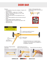
UNIT REMOVAL FROM SKID
FIGURE 3
REMOVAL OF UNIT FROM SKID
It is recommended that the unit not be removed from
the skid with a forklift since the air seal under the unit
could be damaged. See Figure 2.
The shipping brackets on each side of the unit must be
removed and discarded. See Figure 3-A. The return air
grille panel can be removed to provide a place to hold
the unit. The unit can be slid forward on the skid until
the front wheels hang over the edge of the skid. See
Figure 3-B. The unit can be tipped forward and slid
down the edge of the skid until the front wheels touch
the ground. See Figure 3-C. The wheels will not roll.
They are shipped from the factory locked so they will
not roll. The back of the skid will have to be held down
to keep it from tipping up. The skid can be slid out
from under the unit. The unit can then be set upright.
WARNING
This unit is heavy and requires more than one
persontohandleandremovefromtheskid.
Check unit wheels to ensure that wheels are
lockedbeforeremovingfromskid.Extreme
caution must be taken to prevent injury to
personnelanddamagetotheunit.
FIGURE 2
AIR SEAL UNDER QTec UNIT
Air Seal
Hold Skid
Down
A Shipping Brackets B Front Wheels Over Edge
C Front Wheels On Floor

Manual 2100-600
Page 9 of 38
HANDLING UNIT AFTER REMOVAL
FROM SKID
The unit will have to be turned sideways and removed
from the skid to t through a 36" doorway. If the door
height allows, the unit can be slid sideways through the
door.
If the unit can not be slid through the door, then the unit
will have to be put on a cart and tipped down to roll
through the door. It is recommended that an appliance
cart by used with a strap to hold the unit on the cart. The
wheels of the unit must be locked. If the wheels were
allowed to roll, the unit could roll off the cart. The unit
should always be carted from the left side. This is the
side where the compressor is located. See Figure 4.
The blade of the appliance cart should be slid under
the wheels of the unit. The strap of the appliance cart
should be placed around the unit and strapped tightly.
Help will be required to tip the unit back onto the cart.
The unit can be leaned far enough back to be rolled
through the door. Be careful when setting the unit back
up to keep from damaging the unit.
GENERAL
The equipment covered in this manual is to be installed
by trained, experienced service and installation
technicians. A QWS-Series wall sleeve supplied as a
separate accessory must be ordered and installed with
Q-Tec unit.
The unit is designed for use with or without duct work.
For use without duct work, Plenum Box QPB42 is
recommended.
These instructions explain the recommended method
to install the air cooled self-contained unit and the
electrical wiring connections to the unit.
These instructions and any instructions packaged with
any separate equipment required to make up the entire
air conditioning system should be carefully read before
beginning the installation. Note particularly “Start
Procedure” and any tags and/or labels attached to the
equipment.
While these instructions are intended as a general
recommended guide, they do not supersede any
national and/or local codes in any way. Authorities
having jurisdiction should be consulted before the
installation is made. See Page 3 for information on
codes and standards.
Size of unit for a proposed installation should be based
on heat loss calculation made according to methods
of Air Conditioning Contractors of America (ACCA).
The air duct should be installed in accordance
with the Standards of the National Fire Protection
Systems of Other Than Residence Type, NFPA No.
90A, and Residence Type Warm Air Heating and Air
Conditioning Systems, NFPA No. 90B. Where local
regulations are at a variance with instructions, installer
should adhere to local codes.
MINIMUM INSTALLATION HEIGHT
The minimum installation height of the unit with a
Free Blow Plenum is 8 ft. 6 in. This provides enough
clearance for the plenum to be removed. See Figure 5.
The minimum installation height for ducted
applications is 8 ft. 4½ in. This provides enough
clearance to install the duct work. See Figure 6.
FIGURE 4
UNIT ON APPLIANCE CART
WARNING
Exercise extreme caution when pushing the
unitontherollers.Handleandpushfromthe
lower1/3oftheunit.Insurethatdebrisisnot
ontheoorwheretheunitistobemovedon
therollers.Failuretodosocouldresultinthe
unit tipping over and causing bodily injury and/
ordamagetotheunit.
Q-Tec UNIT
(Right Side)
APPLIANCE
CART
STRAP
COMPRESSOR

Manual 2100-600
Page 10 of 38
FIGURE 6
DUCTED APPLICATION
FIGURE 5
INSTALLATION WITH FREE BLOW PLENUM

Manual 2100-600
Page 11 of 38
DUCT WORK
All duct work must be properly sized for the design
airow requirement of the equipment. Air Conditioning
Contractors of America (ACCA) is an excellent guide
to proper sizing. All duct work or portions thereof not
in the conditioned space should be properly insulated in
order to both conserve energy and prevent condensation
or moisture damage. When duct runs through unheated
spaces, it should be insulated with a minimum of one
inch of insulation. Use insulation with a vapor barrier
on the outside of the insulation. Flexible joints should
be used to connect the duct work to the equipment in
order to keep the noise transmission to a minimum.
The Q-Tec series unit has provision to attach a supply
air duct to the top of the unit. Duct connection size is
12 inches x 20 inches. The duct work is eld supplied
and must be attached in a manner to allow for ease of
removal when it becomes necessary to slide the unit out
from the wall for service. See Figure 7 for suggested
attachment method.
The Q-Tec series units are designed for use with free
return (non-ducted) and either free blow with the use of
QPB Plenum Box or a duct supply air system.
The QPB and QPBHW Plenum Box mounts on top
of the unit and has both vertically and horizontally
adjustable louvers on the front discharge grille.
For hot water coil option a QPBHWxx-F for free blow
or QPBHWxx-D for ducted airow is used.
When used with a ducted supply, a QCX Cabinet
Extension can be used to conceal the duct work above
the unit to the ceiling. This extends 20" above the
unit for a total height above the oor of 10'-7/8". The
unit is equipped with a variable speed indoor blower
motor which increases in speed with an increase in duct
static pressure. The unit will therefore deliver proper
rated airow up to the maximum ESP shown in Table
7. However, for quiet operation of the air system, the
duct static should be kept as low as practical, within the
guidelines of good duct design.
FILTERS
Two 1-inch throw away lters [(1) 16x16 and (1)
16x20] are supplied with each unit. The lters slide
into lter brackets. Refer to Figure 8.
The lters are serviced from the inside of the building
by opening the hinged door. This door is attached by a
screw and one locking latch.
The internal lter brackets are adjustable to
accommodate 2-inch lters. The tabs for the 1-inch
lters must be bent down to allow the 2-inch lters to
slide in place.
NOTE: Unit cabinet, supply air duct and free blow
plenum are approved for “0” clearance to
combustible material.
FIGURE 7
SUPPLY DUCT CONNECTIONS
SUPPLY DUCT
TO BE FIELD
SUPPLIED
ATTACHMENT
SCREWS TO
BE FIELD
SUPPLIED
ROOM SIDE OF
Q-T
ec UNIT
DUCT FLANGE
PROVIDED WITH
UNIT
FIGURE 8
FILTER LOCATION
RETURN AIR
GRILLE
FILTERS

Manual 2100-600
Page 12 of 38
FRESH AIR INTAKE
This unit is equipped with a fresh air damper assembly.
The damper blade is locked in the closed position
when the unit is shipped from the factory. To allow
the damper to operate remove the two plastic locking
pins, one on each end of the blade. This will allow for
maximum fresh airow. The damper blade will now
open when the indoor blower is operating. If less than
maximum fresh airow is required, reinsert the plastic
pins to limit damper blade opening to desired level.
Two extra pins are provided (taped to the inside of the
assembly) which may be used to hold the blade in some
position other than minimum or maximum position.
This fresh air assembly is located in the rear of the unit
and to gain access to make these adjustments remove
the air lter service door.
All capacity, efciency and cost of operation
information as required for Department of Energy
“Energyguide” Fact Sheets are based upon the fresh
air blank-off plate in place and is recommended for
maximum energy efciency.
The blank-off plate is available upon request from the
factory and is installed in place of the fresh air damper
shipped with each unit.
For details on energy recovery ventilation see separate
section.
SERVICE LIGHT
The unit is equipped with a service light, which signals
the user that service is required. The light is located
in the upper control panel and is visible only when the
hinged service/lter access door is open.
The Service Unit light indicates that the unit has
been shut off by a high or low pressure device. This
indicates that the unit needs to be serviced.
CONDENSATE DRAIN
There are two drain connections on the unit. The rear
drain is the primary drain, and is located on the right
lower rear panel of the unit. The optional side drain is
located on the bottom right side of the unit. The side
drain is shipped with a plug installed.
The side drain requires a water trap for proper
drainage. See Figure 9. The drain can be routed
through the oor or through the wall. If the drain is to
be routed through an unconditioned space, it must be
protected from freezing. The drain line must be able
to be removed from the unit if it is necessary to remove
the unit from the wall. When the side drain is used, the
plug must be removed and installed in the rear drain
outlet.
The rear drain can be used with wall thickness of up to
10 inches where a water trap can be installed between
the unit and the interior wall. See Figure 10. The trap
cannot extend beyond the edge of the unit or it will
interfere with the wall mounting bracket. The drain can
be routed through the oor or through the wall. If the
drain is routed through the wall, the drain line must be
positioned such that it will not interfere with the sleeve
ange or the grille. See Figure 11. If the drain is to
be routed through an unconditioned space, it must be
protected from freezing.
OPTIONAL REAR DRAIN KITS
Optional Rear Drain Kit, Bard Model QCDS48A,
is also available for these products. The optional
rear drain kit offers multiple benets that include the
following:
• Allows unit to be rolled away from the sleeve
without having to disconnect any hard plumbing
connections.
• Allows indoor coil condensate to be easily
connected to Rear Drain Box while bypassing the
outdoor coil drain pan. This aids in minimizing the
potential for biological growth to occur by
minimizing the standing water and exposing it to
warm temperatures.
See Figures 12A, 12B, 12C and 12D.
The drain box permanently mounts onto the wall sleeve
and is then either piped directly outdoors, or can be
piped vertically. The Q-Tec unit is then equipped with
ttings on the rear of the unit that slide into the drain
box as it is wheeled towards the wall sleeve.
NOTE: On models equipped with a refrigerant
subcooler in the lower drain pan may experience a
2-3% decrease in cooling performance and efciency
when the indoor condensate is routed around the
outdoor coil drain pan/subcooler assembly. Unit
rated performance and efciency are with the indoor
condensate routed to the outdoor coil pan.
There is also a heated version of the rear drain box
available (Model #QCDS48H) for installation in
northern climates where freezing may occur.
SEPARATE EVAPORATOR DRAIN
CONNECTION (OPTIONAL)
A knockout is provided in the back right corner of the
units for use when draining the evaporator drain pan
separately from the condenser. This knockout is 5
inches above the back condenser drain opening. To
utilize a separate evaporator drain connection remove the
knockout and route the existing evaporator drain hose
out this knockout and then to an appropriate drain line.

Manual 2100-600
Page 13 of 38
WATER
TRAP
FIGURE 11
REAR DRAIN (TOP VIEW)
WALL (MAXIMUM
10" FOR REAR
DRAIN)
COUPLINGS NOT
SHOWN BUT
RECOMMENDED
FOR EASE OF
REMOVABILITY
FORSERVICE.
SLEEVE
DRAIN LINE
WALL
BRACKET
UNIT
FIGURE 10
STANDARD REAR DRAIN
FIGURE 9
OPTIONAL SIDE DRAIN (SIDE VIEW) INSTALLATION
Q-Tec UNIT

Manual 2100-600
Page 14 of 38
MIS-2469
DRAIN BOX
WALL SLEEVE
OVERFLOW TUBE
CAULK AROUND TUBE
FIGURE 12A

Manual 2100-600
Page 15 of 38
SUPPLIED WITH DRAIN BOX KIT
3/4" PLASTIC PIPE NIPPLE
HORIZONTAL TO FLOOR)
(TIGHTEN THREADS SO TEE IS
THREADS)
(APPLY TEFLON TAPE TO
REAR DRAIN CONNECTION IN
Q/Tec PRODUCT
1/2" SLIP X 1/2" SLIP X 3/4" NPT
TEE SUPPLIED WITH DRAIN BOX KIT
PLUG INSTALLED IN
SIDE Q/Tec DRAIN
MIS-2470
FIGURE 12B
IMPORTANT !

Manual 2100-600
Page 16 of 38
REMOVE KNOCK-OUT FOR
INDOOR DRAIN HOSE CONNECTOR
MIS-2471
FIGURE 12C
(If Used)

Manual 2100-600
Page 17 of 38
MIS-2472
DRAIN HOSE FROM INDOOR
DRAIN PAN.
MOVE HOSE FROM ATTACHMENT IN
LOWER DRAIN PAN AND SLIDE ONTO
DRAIN BOX BARB FITTING, SECURING
WITH SUPPLIED CLAMP IF OUTDOOR
PAN IS BYPASSED. ( WILL REDUCE RISK
OF ALGAE GROWTH IN THE OUTDOOR
PAN BUT AT A SLIGHT COOLING
PERFORMANCE REDUCTION OF 2-3% )
FIGURE 12D

Manual 2100-600
Page 18 of 38
Washer
Sleeve
Stud
MIS-2689
Nut
Lower Control Panel
Condenser
Door (Removed)
Return Grille
FIGURE 13A
UNIT MOUNTING
BOTTOM
TRIM PIECE
BOTTOM TRIM
EXTENSION
MOUNTING
BRACKET
SIDE TRIM
(2PCS.)
SIDE TRIM
(2PCS.)
CABINET
SIDE PANEL
ENLARGED VIEW OF MOUNTING
BRACKET SHOWING SLEEVE TO
CABINET ATTACHMENT
MOUNTING BRACKET
#8 SCREW
PROVIDED
(LIGHT COLOR)
WALL
SLEEVE
#10 HEX
HEAD SCREW
PROVIDED
FIGURE 13B
UNIT MOUNTING

Manual 2100-600
Page 19 of 38
INSTALLATION INSTRUCTIONS
MOUNTING THE UNIT
When installing a Q-Tec unit near an interior wall on
the left side, a minimum of 8 inches is required; 12
inches is preferred.
When installing a Q-Tec unit near an interior wall on
the right side, a minimum of 18 inches is required as
additional space is required to connect the side drain.
If the rear condensate drain kit QCDS48 is used the
minimum can be reduced to 8 inches.
This clearance is required to allow for the attachment of
the unit to the sleeve and side trim pieces to the wall.
This unit is to be secured to the wall sleeve with
mounting brackets provided. The unit itself, the supply
duct and the free blow plenum are suitable of “0”
clearance to combustible material.
Following are the steps for mounting the Q-Tec. For
reference see Figure 13A for external mounting bracket
or 13B for internal bolt secured bracket (recommended).
1. Attach mounting brackets to the wall sleeve with
screws provided. Either use external mounting
bracket (Fig. 13A) or internal bolt bracket (Fig. 13B).
2. Position the unit in front of the sleeve with the
condenser section toward the sleeve.
3. Remove the locking screws from the wheels.
Refer to Figure 14.
4. Roll the unit into the sleeve. Make sure to check
both sides of the unit as it is being rolled to
keep it centered in the sleeve. Also check the
alignment to the mounting brackets. This unit
must be level from side to side. If adjustments
are necessary, shim up under the rollers with
sheets of steel or any substance that is not
affected by moisture.
5. Make sure the gasket on the rear of the unit is
touching the sleeve across the top and down both
sides. This is a rain water seal.
6. Secure the mounting brackets to the unit with
screws provided, #10 hex head sheet metal
screws (Figure 13A) or use nut and washer to
secure sleeve (Figure 13B).
7. Bottom trim extensions are provided for use when
wall is less than 14 inches but greater than 10.5
inches. Secure to wall with screws (not provided).
8. Attach the bottom trim piece to the unit with the
screws provided (dark colored).
9. Position side trim pieces to wall and attach with
eld supplied screws. There are two long pieces
and two short pieces supplied. The long pieces
are to enclose the gap behind the unit. The
short pieces are to ll the gap behind the cabinet
extension or the free blow plenum box. They
may be cut to suit your ceiling height or overlap
the unit side trim. There is sufcient length to
trim up to a 10'2" ceiling.
NOTE: If the exterior wall thickness is between 5
inches to 10.5 inches, a side trim extension
piece kit, model QSTX42, is available.
REMOVE SCREWS FROM WHEELS
BEFORE ROLLING INTO PLACE
FIGURE 14
REMOVING LOCKING SCREWS FROM WHEELS

Manual 2100-600
Page 20 of 38
WIRING – MAIN POWER
Refer to the unit rating plate and/or Table 2 for wire
sizing information and maximum fuse or “HACR
Type” circuit breaker size. Each unit is marked with
a “Minimum Circuit Ampacity”. This means that the
eld wiring used must be sized to carry that amount
of current. Depending on the installed KW of electric
heat, there may be two eld power circuits required. If
this is the case, the unit serial plate will so indicate. All
models are suitable only for connection with copper
wire. Each unit and/or wiring diagram will be marked
“Use Copper Conductors Only”. These instructions
MUST BE adhered to. Refer to the National Electrical
Code (NEC) for complete current carrying capacity
data on the various insulation grades of wiring material.
All wiring must conform to NEC and all local codes.
The electrical data lists fuse and wire sizes (75°C
copper) for all models, including the most commonly
used heater sizes. Also shown are the number of eld
power circuits required for the various models with
heaters.
The unit rating plate lists a “Maximum Time Delay
Relay Fuse” or “HACR Type” circuit breaker that is to
be used with the equipment. The correct size must be
used for proper circuit protection, and also to assure that
there will be no nuisance tripping due to the momentary
high starting current of the compressor motor.
FIGURE 15
COMPONENT LOCATION
TABLE 3
OPERATING VOLTAGE RANGE
NOTE: The voltage should be measured at the eld
power connection point in the unit and while
the unit is operating at full load (maximum
amperage operating condition).
The disconnect access door on this unit may be locked
to prevent unauthorized access to the disconnect.
See “Start Up” section for information on three phase
scroll compressor start-ups.
The eld wiring connections are located behind the top and
hinged panel in the circuit breaker panel. See Figure 15.
WIRING – LOW VOLTAGE WIRING
230/208V, 1 PHASE AND 3 PHASE EQUIPMENT
DUAL PRIMARY VOLTAGE TRANSFORMERS.
All Equipment leaves the factory wired on 240V tap.
For 208V operation, reconnect from 240V to 208V tap.
The acceptable operating voltage range for the 240 and
208V taps are as noted in Table 3.
TAP RANGE
240V 253 – 216
208V 220 – 187
OPTIONAL CLIMATE CONTROLS
SEQUENCE OF OPERATION
The standard Climate Control Option X is a remote
thermostat connection terminal block. See Figure 17 for
wiring diagram. Compatible thermostats are listed in
Table 4.
The Climate Control Option D is an electronic,
programmable thermostat. The subbase of the thermostat
is factory wired to the front panel of the unit. See Figure
19 for wiring diagram. Compatible for use with Energy
Recovery Ventilator or Economizer. The thermostat can
be set in the heat, cool or automatic mode. When the
thermostat is sent in the heat mode, it can heat only to
maintain the temperature set on the thermostat. When
the thermostat is set in the cool mode, it can cool only
to maintain the temperature set on the thermostat.
When the thermostat is set in the automatic mode, the
thermostat can change automatically to the heat or cool
modes to maintain the temperature set on the thermostat.
The Climate Control Option H is an electronic,
programmable thermostat and a CO
2
controller. The
subbase of the thermostat and CO
2
controller are factory
wired to the front panel of the unit. See Figure 20
for wiring diagram. The thermostat can be set in the
heat, cool or automatic mode. When the thermostat is
set in the heat mode, it can heat only to maintain the
temperature set on the thermostat. When the thermostat
is set in the cool mode, it can cool only to maintain the
temperature set on the thermostat. When the thermostat
is set in the automatic mode, the thermostat can change
automatically to the heat or cool modes to maintain the
temperature set on the thermostat.
DEHUMIDIFICATION
CONTROL
(OPTIONAL)
UNIT
MOUNTED
THERMOSTAT
LOCATION
ELECTRIC
HEATERS
CIRCUIT
BREAKER PANEL
& CONTROLS
I
NDOOR
BLOWER
SIDE FIELD WIRE
ENTRANCE
LOWER
CONTROL
PANEL
REMOTE
THERMOSTAT
TERMINAL
BLOCK
/