Philips AZ2536 User manual

Category
CD players
Type
User manual
MP3/VCD CD Sound Machine
AZ 2536
all versions
Handling Chip Components and Safety ..........................1 - 1
Technical Specification & Service tools...........................2 - 1
Service Measurement......................................................2 - 2
Connections and controls.......................................3 - 1..3 - 2
Instruction for use...................................................3 - 3..3 - 5
Disassembly Diagram......................................................4 - 1
Block Diagram .................................................................5 - 1
Wiring Diagram................................................................5 - 2
LCD & MCU Board
Circuit diagram........................................................6 - 1
Layout diagram........................................................6 - 2
VCD Board
Circuit diagram........................................................7 - 1
Layout diagram........................................................7 - 2
MTF Board
Circuit diagram .......................................................8 - 1
Layout diagram .......................................................8 - 2
Tuner Board
Circuit diagram .......................................................9 - 1
Layout diagram .......................................................9 - 2
Tuner adjustment table ...........................................9 - 2
Power Board
Circuit diagram......................................................10 - 1
Layout diagram......................................................10 - 2
Exploded view diagram (main set) ................................11 - 1
Mechanical partslist ......................................................11 - 2
Electrical partslist...........................................................11 - 2
(Circuit and Layout diagram for referrence only)
© 3141 785 30040
Published by LX 0428 Service Audio Printed in The Netherlands Subject to modification
CLASS 1
LASER PRODUCT
TABLE OF CONTENTS
©
Copyright 2004 Philips Consumer Electronics B.V. Eindhoven, The Netherlands
All rights reserved. No part of this publication may be reproduced, stored in a retrieval
system or transmitted, in any form or by any means, electronic, mechanical, photocopying,
or otherwise without the prior permission of Philips.
version1.0
VIDEO CD
HANDLING CHIP COMPONENTS
© WARNING
All ICs and many other semiconductors are susceptible to
electrostatic discharges (ESD). Careless handling during
repair can reduce life drastically.
When repairing, make sure that you are connected with the
same potential as the mass of the set via a wristband with
resistance. Keep components and tools at this potential.
f ATTENTION
Tous les IC et beaucoup d´autres semi-conducteurs sont
sensibles aux décharges statiques (ESD). Leur longévite
pourrait être considérablement écourtée par le fait qu´aucune
précaution nést prise à leur manipulation.
Lors de réparations, s´assurer de bien être relié au même
potentiel que la masse de l´appareil et enfileer le bracelet
serti d´une résistance de sécurité.
Veiller à ce que les composants ainsi que les outils que l´on
utilise soient également à ce potentiel.
d WARNUNG
Alle ICs und viele andere Halbleiter sind empfindlich
gegenüber elektrostatischen Entladungen (ESD).
Unsorgfältige Behandlung im Reparaturfall kann die
Lebensdauer drastisch reduzieren.
Sorgen Sie dafür, daß Sie im Reparaturfall über ein Puls-
armband mit Widerstand mit dem Massepotential des
Gerätes verbunden sind.
Halten Sie Bauteile und Hilfsmittel ebenfalls auf diesem
Potential.
ñ WAARSCHUWING
Alle IC´s en vele andere halfgeleiders zijn gevoelig voor
electrostatische ontladingen (ESD).
Onzorgvuldig behandelen tijdens reparatie kan de levensduur
drastisch doen vermindern. Zorg ervoor dat u tijdens reparatie
via een polsband met weerstand verbonden bent met hetzelfde
potentiaal als de massa van het apparaat.
Houd componenten en hulpmiddelen ook op ditzelfde potentiaal.
i AVVERTIMENTO
Tutti IC e parecchi semi-conduttori sono sensibili alle scariche
statiche (ESD).
La loro longevità potrebbe essere fortemente ridatta in caso di
non osservazione della più grande cauzione alla loro
manipolazione. Durante le riparationi occorre quindi essere
collegato allo stesso potenziale che quello della massa
delápparecchio tramite un braccialetto a resistenza.
Assicurarsi che i componenti e anche gli utensili con quali si
lavora siano anche a questo potenziale.
©
Safety regulations require that the set be restored to its
original condition and that parts which are identical with
those specified be used.
Safety components are marked by the symbol
i
Le norme di sicurezza estigono che l´apparecchio venga
rimesso nelle condizioni originali e che siano utilizzati i
pezzi di ricambiago identici a quelli specificati.
Componenty di sicurezza sono marcati con
ñ
Veiligheidsbepalingen vereisen, dat het apparaat in zijn
oorspronkeliijke toestand wordt teruggebracht en dat
onderdelen, identiek aan de gespecificeerde, worden toegepast.
De Veiligheidsonderdelen zijn aangeduid met het symbool
s Varning !
Osynlig laserstrålning när apparaten är öppnad och
spärren är urkopplad. Betrakta ej strålen.
Advarsel !
Usynlig laserstråling ved åbning når sikkerhedsafbrydere
er ude af funktion. Undgå udsaettelse for stråling.
ß Varoitus !
Avatussa laitteessa ja suojalukituksen ohitettaessa olet alttiina
näkymättömälle laserisäteilylle. Älä katso säteeseen !
f
"Pour votre sécurite, ces documents doivent être utilisés par
des spécialistes agréés, seuls habilités à réparer votre
appareil en panne".
ESD
SAFETY
d
Bei jeder Reparatur sind die geltenden Sicherheitsvor-
schriften zu beachten. Der Originalzustand des Gerätes
darf nicht verändert werden. Für Reparaturen sind Original-
ersatzteile zu verwenden.
Sicherheitsbauteile sind durch das Symbol markiert.
f
Les normes de sécurité exigent que l`appareil soit remis
à l`état d`origine et que soient utilisées les pièces de
rechange identiques à celles spécifiées.
Les composants de sécurité sont marqués
CLASS 1
LASER PRODUCT
©
DANGER: Invisible laser radiation when open.
©
After servicing and before returning the set to customer
perform a leakage current measurement test from all
exposed metal parts to earth ground, to assure no
shock hazard exists.
The leakage current must not exceed 0.5mA.
AVOID DIRECT EXPOSURE TO BEAM.
1 - 1
GENERAL
Mains voltage
:
-/01 120V/230 V
:
-/10 240 V
Mains frequency
:
-/01 : 60 Hz/50Hz
:
-/10 : 50 Hz
Battery
mains : 12 V (R20 x 8)
Power consumption
:
Dimension (W x H x D)
:
480 x
260 x 170 mm
AMPLIFIER & MAX PART
Output power mains : 2 x 4 W
battery : 2 x 4 W
Residual noise : 60nW (volume minimum)
Channel difference : 3dB typ. at 500mW
Hum & noise : 500nw (Vol.max.-20dB)
TUNER - FM SECTION
Tuning range : 87.5 - 108 MHz
IF frequency : 10.7 MHz
Sensitivity : < 25 dBf at 26dB S/N
Selectivity : > 20 dB at S9/300kHz
±0.02MHz
IF rejection : > 50 dB
Image rejection : > 20 dB
TUNER - MW SECTION
Tuning range :
:
9kHz 531 - 1602 kHz
10kHz 530 - 1700 kHz
IF frequency : 450 kHz ± 1 kHz
Sensitivity : < 5000 µV/m at 26dB S/N
Selectivity : 16 dB
:
IF rejection ratio 24 dB
:
Image rejection 28 dB
< 24 W
Frequency response :
>
>
>
COMPACT DISC
:
S/N ratio > 50 dB
:
> 5 g
+10dB ±2dB at 100Hz
Channel difference : < 3 dB
:
THD (1KHz,-6dB) <1%
:
THD (10KHz,-20dB) <3%
Crosstalk
1 kHz : > 26 dB
Crosstalk
10 kHz : > 16 dB
at S9/300kHz
(500mW output WOOX ON)
Frequency response : +1dB ±2dB at 10kHz
(500mW output WOOX ON)
Shock resistance
±Z axis
:
> 5 g
±X or ±Y axis
:
35dBAmax.(mode:play/pause)
Acoustical noise
:
45dBAmax. (mode:jump)
2 - 1
SERVICE TOOLS
Audio signal disc SBC 429.......................................................................4822 397 30184
Playability test disc SBC 444
...................................................................4822 397 30245
Test disc 5 (disc without errors ) +
Test disc 5A (disc with dropout errors, black spots and fingerprints)
SBC 426/426A.....................................................................4822 397 30096
Burn in test disc (65 min. 1kHz signal at -30 dB level without “pause”)
.....4822 397 30155
anti-static table mat
large 1200x650x1.25mm 4822 466 10953
small 600x650x1.25m 4822 466 10958
anti-static wristband
4822 395 10223
connection box (3 press stud connections, 1M) 4822 320 11307
extendible cable (2m, 2M, to connect wristband to connection box) 4822 320 11305
connecting cable (3m, 2M, to connect table mat to connection box) 4822 320 11306
earth cable (1M, to connect any product to mat or to connection box) 4822 320 11308
KIT ESD3 (combining all 6 prior products - small table mat) 4822 310 10671
wristband tester 4822 344 13999
AVAILABLE ESD PROTECTION EQUIPMENT
TECHNICAL SPECIFICATIONS
2 - 2
SERVICE MEASUREMENT
Bandpass
250Hz-15kHz
e.g. 7122 707 48001
LF Voltmeter
e.g. PM2534
DUT
RF Generator
e.g. PM5326
S/N and distortion meter
e.g. Sound Technology ST1700B
Tuner SW
To avoid atmospheric interference all AM-measurements have to be carried out in a Faraday´s cage.
Use a bandpass filter (or at least a high pass filter with 250Hz) to eliminate hum (50Hz, 100Hz).
Ri=50
Aerial replacement
Capacitor
R=50
Bandpass
250Hz-15kHz
e.g. 7122 707 48001
LF Voltmeter
e.g. PM2534
DUT
S/N and distortion meter
e.g. Sound Technology ST1700B
Frame aerial
e.g. 7122 707 89001
Tuner AM (MW,LW)
To avoid atmospheric interference all AM-measurements have to be carried out in a Faraday´s cage.
RF Generator
e.g. PM5326
Ri=50
Low pass filter 22kHz
L
R
LEVEL METER
e.g. Sennheiser UPM550
with FF-filter
S/N and distortion meter
e.g. Sound Technology ST1700B
DUT
CD
Use Audio Signal Disc SBC429 4822 397 30184 (replaces test disc 3)
L.P.F. = 13
th
order filter 4822 395 30204
3 - 1
#
$
%
6
5
4
3
&
^
7
8
9
1
2
0
!
@
LOURD !
Soin de prise de votre Soundmachine
CD. Saisissez les deux poign
ées quand
vous portez ou déplacez l'appareil.
Take care of your CD Soundmachine.
Grip both handles when you carry or
lift the set.
HEAVY !
Take care of your CD Soundmachine.
Grip both handles when you carry or
lift the set.
HEAVY !
Take care of your CD Soundmachine.
Grip both handles when you carry or
lift the set.
HEAVY !
CONTROLS
Remote Control
. . . . . . . . . . . . . . . . . . . .1 pc
AC Power Cord
. . . . . . . . . . . . . . . . . . . .1 pc
Audio / Video Cable
. . . . . . . . . . . . . . . .1 pc
1 LCD Display - shows the status of the set
2 [dB]: - meter to indicate bass power
3 STANDBY ON y -switches the set on/off
4 VOLUME -
adjusts volume or equalizer level
5
SOURCE - selects sound source for functions:
CD • VCD, FM, MW, TAPE
6
p
-3.5 mm stereo headphone jack
Helpful hints: The speakers will be muted
when headphones are connected to the set.
7
Cassette recorder keys
PAUSE ;
-
pauses playback or recording
STOP
OPEN 9 /
-
opens the cassette compartment
-
stops the tape
SEARCH 5 /6
-
fast winds/rewinds tape
PLAY 1
-
starts playback
RECORD 0
-
starts recording
8 OPEN•CLOSE -press to open/close CD door
9 MIC -jack to connect microphones
VOL - adjust the mixing level for karaoke
0 ALBUM/PRESET -, +
MP3-CD: selects previous/next albums
FM/MW: selects a preset radio station
SEARCH , §
§
-
CD/MP3-CD: - searches backward or forward;
- skips to the beginning of a
current track/ previous/ later
track.
FM/MW:
tunes to radio stations
2; -s
tarts or pauses CD playback
9 -stop
CD
playback;
- erases a CD program.
!
IR SENSOR
-
infrared sensor for remote
control
@ EQUALIZER - selects bass, mid and high
frequencies
PROG -
CD/VCD/MP3-CD:
programs tracks and
reviews the programmed
songs
FM/MW:
programs preset radio stations
MODE - selects different CD/VCD/MP3-CD
play modes: e.g. REPEAT or SHUFFLE
order
MAX SOUND - actives or deactivates the
optimal mix of various sound
features
# Telescopic aerial - improves FM reception
$ Voltage selector (some versions only) - adjusts
to match the local voltage 110/220V before
plugging in the set.
% Battery door - opens the battery compartment
^ AC MAINS - Socket for power cord
& AUDIO / VIDEO SOCKET - connects to a TV
set
1
y
/
1
1
-switches the set to standby / on if set
operating on AC power. (Switches the set
off only if it is battery-powered)
2 DIGITS 0 - 9
CD/VCD/MP3-CD: selects a track number.
(numbers consisting more than 2 figures must
be keyed in within 2 seconds)
3 MODE - selects different CD/VCD/MP3-CD
play modes: e.g. REPEAT or SHUFFLE
order
4 5 or 6 -
CD/VCD/MP3-CD: searches backward or
forward
FM/MW:
tunes to radio stations
5 VOL -/+ -
adjusts volume or equalizer level
REMOTE CONTROL
BACK PANEL
TOP AND FRONT PANEL
SUPPLIED ACCESSORIES
CONTROLS
6 ¡ , -
CD/VCD/MP3-CD: selects previous/next tracks
FM/MW: selects a preset radio station
7 EQ - selects bass, mid and high frequencies
8 VIEW - scans through a VCD with 9 pictures
display on TV screen. Only when PBC mode is
switched off (for VCD operation only).
9 OSD - switches on/off the on screen display on
the TV screen.
0 SLOW - watches a VCD at a slower speed (for
VCD operation only).
! RESUME - resumes playback in stop mode.
@ GOTO - starts playback at any chosen time on
the disc (for CD/VCD operation only and PBC
mode is off).
# MIX/SEL - selects disc format (CD/MP3-CD) in
a mixed mode disc.
$ ECHO + / ECHO
- - adjusts the VCD echo level
for karaoke after you inserted a microphone.
% KEY+ / KEY- - changes the VCD key tone to suit
to your vocal range.
^ L/R/ST - selects channel left / channel right /
stereo sound, or selects a language in a
bilingual VCD.
& A -
2 B - plays a certain scene or passage
repeatedly (for CD/VCD operation only).
* NTSC/PAL - selects the video output for NTSC
or PAL system.
( ZOOM (for VCD operation only)
zooms in or zooms out pictures.
) PBC (PLAYBACK CONTROL) - switches on or
off PBC mode (for VCD version 2.0 only).
¡ RETURN - returns to the previous MENU level
during playback (for VCD with PBC on).
9 - stops playback or clears a programme.
£ 2/; - starts or interrupts playback.
4 (album down) - selects previous albums (for
MP3-CD only)
MAX - selects special bass enhancement
on/off
§ 3 (album up) - selects next albums (for MP3-
CD only)
PROG -
CD/VCD/MP3-CD:programme tracks and
reviews programmed songs.
FM/MW:
programs preset radio stations
1
123
456
7
PROG MODE
VOLVOL
PBC
NTSC/PAL
L/R/ST
KEY
ECHO
MIX SEL GOTOA B
ZOOM SLOW RESUME
RETURN VIEW OSD
EQ
MAX
8
0
9
2
3
4
5
6
7
9
!
$
%
#
@
0
8
£
¡
^
*
)
(
&
§
27
24
POWER SUPPLY
IMPORTANT!
For best CD/MP3-CD/VCD playback, please plug in your set to an AC power supply where
convenient.
If operated in DC mode, see below approximate playtime. (Playtime is also varied from
different brand batteries) :
The CD part of this system also serves as a Video CD player if you connect it to your TV
set.
Before viewing the Video CD, ensure that the set is switched to corresponding PAL or
NTSC system of your TV set (exception Multi-system TV).
Whenever convenient, use the mains supply if you want to conserve battery life. The battery supply
will be switched off when the set is connected to the mains.
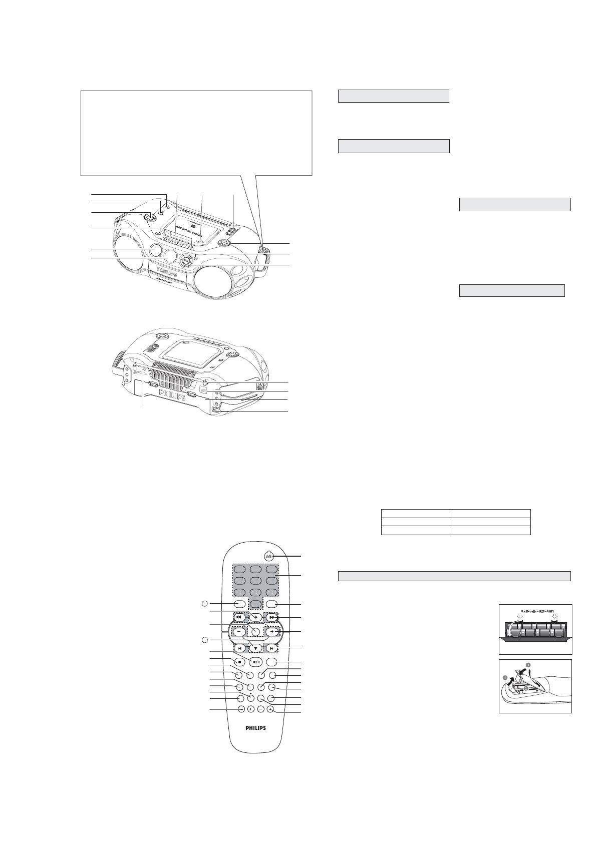
Make sure you remove the plug from the
set and wall outlet before inserting batteries.
Batteries
1. Open the battery compartment and insert six batteries, type
R20, UM1 or D-cells, (preferably alkaline) with the correct
polarity as indicated by the "
+" and "-" symbols inside the
compartment.
Remote control
Open the battery compartment and insert two batteries,
type AA, R6 or UM3 (preferably alkaline).
2. Replace the compartment door, making sure the batteries are
firmly and correctly in place.
3. Remove the batteries if they are exhausted or if they will not be
used for a long period.
– The incorrect use of batteries can cause electrolyte leakage
and will corrode the compartment or cause the batteries to burst. Therefore:
–Do not mix battery types, e.g. alkaline with zinc carbonate.
–When inserting new batteries, replace all at the same time.
–Remove the batteries if the set is not to be used for a long time.
Helpful hints:
–The battery supply is switched off when the set is connected to the mains.
Batteries contain chemical substances, so they should be disposed of properly
TV screen is disabled during CD / MP3-CD playing if your AZ2536 is
battery powered.
BATTERIES (NOT SUPPLIED)
Battery type Playtime
Alkaline approximate 9 hrs
Zinc Carbonate approximate 2hrs
CONNECTIONS AND CONTROLS
3 - 2
GENERAL OPERATION
1. Check if the mains voltage as shown on the type plate (on the
bottom of the set) corresponds to your local mains voltage.
Select 110 or 220V by the selector (for some version only).
2. If your set is equipped with a voltage selector, adjust the
selector so that it matches with the local mains.
3. Connect the mains lead to the AC MAINS
~ socket and the
wall socket.
The set is now ready for use.
4. To switch off the mains supply completely, pull the mains plug out of the wall socket.
Disconnect the mains lead when you change over to battery supply, or to protect the set
during heavy thunderstorms.
The type plate is located on the bottom of the set.
CONNECTING TO YOUR TV SYSTEM
MAINS
R
e
d
Y
e
l
l
o
w
W
h
i
t
e
CONNECTIONS AND CONTROLS
GENERAL OPERATION
1.
Press STANDBY ON
y
on the set to switch on.
2.
Press SOURCE once or more to select your desired function:
CD • VCD, FM, MW, TAPE
3.
Press STANDBY ON
y
to switch the set to standby.
Helpful hints :
To change from
TAPE
to
CD • VCD,
FM
or
MW
source, or when you are switching off the set:
first, make sure you press the tape
STOP
9
key to end playback and all the cassette keys are
released.
The tone, sound settings, tuner presets and the volume level (up to a maximum volume level of
VOL 20
) will be retained in the set's memory.
1.
Adjust the volume with the VOLUME control.
= Display shows the volume level and a number from 0-
32.
2.
MAX SOUND
To enhance the bass response: press MAX SOUND once or more to
switch on / off.
= MAX SOUND-key backlight lights up when MAX SOUND is
turned on.
Helpful hints :
MAX SOUND can be used when you play CD, VCD, FM, MW and TAPE
source.
Some discs might be recorded in high modulation, which causes a distortion at high volume. If this
occurs, deactivate MAX SOUND or reduce the volume.
3.
EQUALIZER
To adjust the bass, mid and high frequencies, press EQUALIZER once
or more (or press EQ on the remote control), then rotate VOLUME
within 3 seconds to adjust each level.
=Display briefly shows
,
, or
level (-5 to
+5) or
.
Helpful hints:
EQUALIZER can be used during CD, VCD, FM, MW and TAPE
source.
To prevent sound interference the bass control options operate exclusively.
You cannot combine the bass from EQUALIZER with MAX SOUND
ADJUSTING VOLUME AND SOUND
SWITCHING ON AND OFF
DIGITAL TUNER
Tuning to stations
1.
Press STANDBY ON
y
to on, then press SOURCE once or more to select
FM/MW
.
= Display: shows waveband, frequency, and preset station number if already stored.
2.
Tuning to stations: you can tune to your stations manually or by
automatic search tuning:
Press down on
or §
§
§
(
5 or 6
on the remote control) and
release button when the frequency in the display starts running.
= The radio automatically tunes to a station of sufficient
reception. Display shows
during automatic tuning.
3.
Repeat step 2 if necessary until you find the desired station.
To tune to a weak station, press
or §
(
5 or 6
on the remote control) briefly and repeatedly
until you have found optimal reception.
Changing tuning grid (some versions only)
In North and South America the frequency step between adjacent channels in the AM and FM band
are 10 KHz and 100 KHz respectively. In the rest of the world this step is 9 KHz and 50 KHz. Usually
the frequency step has been preset in the factory for your area if not
:
1.
Select TUNER source.
2.
Press MODE on the set for at least 6 seconds.
= The display shows either or
.
Helpful hints:: All preset stations will be lost and need to be reprogrammed.
To improve radio reception:
For FM, extend, incline and turn the telescopic antenna. Reduce
its length if the signal is too strong.
For MW, the set uses a built-in antenna. Direct this antenna by
turning the whole set.
RADIO RECEPTION
3 - 3
INSTRUCTION FOR USE
CD/VCD/MP3-CD
This set can play all digital audio CD, video CD, finalised digital
audio CD-Recordable (CDR) discs and finalised digital audio CD-
Rewritable (CDRW) discs.
Support following MP3-CD formats:
ISO 9660 or ISO 9660 + Joliet format - Max. 30 characters
Max. Track number is 400
Max. nested directory is 8 levels
The max. album number is 99
The max. MP3 programme track number is 20
The max. length of each track is 99 minutes 59 seconds
The player can play mixed mode disc of CD / MP3-CD
Supported VBR bit-rate
Supported sampling frequencies for MP3 disc : 8 kHz to 48 kHz (44.1kHz preferably)
Supported bit-rates of MP3 disc are: 32 - 320 kbps (128 kbps preferably)
Following formats are not supported
The files like *.WMA, *AAC, *.DLF, *.M3U, *.PLS, MP3 PRO
The non-session closed discs
1. Press
STANDBY ON y
once or more to on, then select
CD • VCD
SOURCE.
2. Press OPEN
CLOSE to open the CD door.
is displayed when the CD door is open.
3. Insert a CD with the printed side facing up and press down on OPEN
CLOSE to close the CD door.
Display show , then 001 (track number) and elapsed time.
will be displayed if no disc is inserted or error in CD operation.
4. Playback starts from the beginning of the 1st track automatically.
For MP3-CD only
The current track number "XXX" and current album number
AXX" will be displayed interchangeably.
On TV screen, the album list appears on the left and track list
on the right (max. 10 lines per page). The current selected
music is highlighted, with the elapsed time shown at the upper
right corner.
Helpful hints:
- To ensure good system performance, wait until the disc completely reads before proceeding.
- For MP3-CD, the disc reading time may exceed 1 minute due to the large number of songs
compiled into one disc.
PLAYING A DISC
DISCS FOR PLAYBACK
CD/VCD/MP3-CD
Press
2;
to start playback if in the stop position.
The current track number and elpased time appear on the
display.
To interrupt playback, press
2;
.
The current track number will start flashing.
To resume playback, press
2;
again.
To stop playback, press 9.
To select a desired track
Press
or §
§
§
§
§
§§
on the set repeatedly (or use digits 0 - 9 buttons or press
¡ ,
on the remote
control) until the desired track appears on the display.
If playback is stopped, press
2;
to start playback.
To search for a particular passage during playback
Either press and hold
or §
on the set for 1 second, and then release
or §
to select the
passage
or press
5 or 6
on the remote control and then press
2;
to select the passage.
During searching, the volume will be muted.
For MP3-CD only
To select a desired album
Press
ALBUM/PRESET -, +
on the set repeatedly (or press
3 or 4
on the remote control ) until the
desired album number appear on the display.
"AXX" will be displayed.
On TV screen, the arrow will move forward/backward in the ALBUM menu.
To select a desired track
Press
or §
on the set repeatedly (or on the remote control, press
¡ ,
) to select a desired track
from the current album.
"XXX" will be displayed.
On TV screen, the arrow will move forward/backward in the TRACK menu.
Use the digital keys on the remote control to select the track under current album directly.
For VCD only
•Either p
ress
5 or 6
on the remote control repeatedly to select fast search speed (x1, x2, x3 or x4)
or press & hold
or §
on the set for 1 second and then release
or §
to select fast search
speed (x1). Repeat this step to select other speed (x2, x3 or x4).
SELECTING A DESIRED TRACK/PASSAGE
CD/VCD/MP3-CD
Programming tracks of disc is possible when playback is stopped. Up to 20 tracks can be stored in
the memory in any order.
1.
In stop mode, press PROG to enter program setting.
PROG
will start flashing and " P01" will be displayed.
On TV screen, "PROG" program list (5 lines per page) will be displayed.
2.
Press
/ §
§
§
(or use digits 0 - 9 or press
¡,
on the remote control) to select the desired track.
MP3-CD mode only:
First press
ALBUM/PRESET -, +
once or more (or press digits 0 - 9 or
3/ 4
on the remote
control) to find your album, press PROG to store the selected album, and then press
/ §
(or use digits 0 - 9 or press
¡,
on the remote control) to select the desired track.
3.
Press PROG to confirm the track number to be stored.
Display shows " P02", indicating the next program location available.
4.
Repeat steps 1-3 to select and store all desired tracks.
Display: if you try to program more than 20 tracks.
5.
Press
2;
to play the programmed tracks.
If you select REPEAT/REPEAT ALL during program playback, the current track or all programmed
tracks will be played repeatedly.
REPEAT/REPEAT ALL icon and PROG will appear on the display.
Reviewing the program
In the stop position, press PROG repeatedly to see your stored track numbers.
The display first shows the number of program location and then, the number of the track stored
here.
For MP3-CD only: The display first shows the number of program location and then, the album
number for the track stored here. To see the track number, press PROG again.
Erasing a program
You can erase the contents of the memory by:
opening the CD door;
selecting FM, MW or TAPE sound sources;
•pressing
9
twice during playback or once in the stop position.
= PROG disappears.
PROGRAMMING TRACKS
CD/VCD/MP3-CD
You can play all the tracks in random order.
1. During playback, press MODE once or more.
SHUFFLE will appear on the display.
2. To select normal playback, press MODE repeatedly until the various modes are no longer
displayed.
–You can also press the
9
to cancel your play mode in playing.
You can play the current track, the program or the whole disc repeatedly.
1. During playback, press MODE once or more.
REPEAT - plays the current track continuously
REPEAT ALL - repeats the entire CD/ program
2.To select normal playback, press MODE repeatedly until the various modes are no longer
displayed.
–You can also press the
9
to cancel your play mode in playing.
Adjusting the TV System
Before viewing the Video CD, ensure that the set is switched to corresponding PAL or NTSC system
of your TV set (except for Multi - system TV).
1. On the remote control, press NTSC/PAL to switch between NTSC and PAL TV system.
OSD - On Screen Display
If you insert VCD/CD, your TV screen will serve as an additional display for messages (e.g. PLAY,
STOP), and information stored on the VCD/CD.
Press OSD on the remote control to select viewing various information.
The elapsed time, remaining time in the track/disc (SINGLE REMAIN / TOTAL REMAIN) and
EQUALIZER bars appear on the display.
Helpful hints:
- For a MP3-CD, TOTAL REMAIN is not available.
- For a VCD, SINGLE REMAIN is not available.
VIDEO CD
REPEAT
SHUFFLE
3 - 4
CD/VCD/MP3-CD
A-
2
B repeat
This feature is also applicable to audio CD (except for MP3-CD). To Play a certain scene or passage
of the disc repeatedly,
1.Press A-
2
B on the remote control during playback to mark the start point of the chosen scene or
passage.
"REPEAT A" will appear on the screen.
2. Press A-
2
B again to mark the end of the chosen scene or passage.
"REPEAT AB" will appear on the screen.
The selected scene or passage will start playing repeatedly.
3. Press A-
2
B once more to return to normal playback.
"REPEAT AB" will disappear from the display.
Helpful hints:
- You can also cancel A-
2
B repeat by pressing
¡ or
.
- The A-
2
B repeat marking can only be set within the same track.
Resume
In stop mode, press RESUME on the remote control to start playback again from where you have
stopped.
Helpful hints:
- Resume will not be available if you have changed the disc, opened the disc tray or disconnected
the system from the power supply.
View
This feature allows you to scan through a VCD for a quick review. PBC mode must be switched off.
1. In stop mode, press VIEW on the remote control to go to disc view function.
On TV screen, up to 9 pictures will be displayed. If a menu consists of more than one page,
press
¡
or
to view the previous/next page.
The first several seconds of each track will be played.
To exit review mode, press digits 0 - 9 to play the desired track or
2;
to play the current
selected track.
2. In playback mode, press VIEW on the remote control to go to track view function.
press
¡
or
to select the track.
On TV screen, up to 9 pictures within the track will be displayed.
The first several seconds of each picture will be played.
To exit review mode, press digits 0 - 9 to play the desired position within the track or
2;
to
play the current selected position.
Helpful hints:
- If the disc is AVCD disc and there're no video tracks on the same viewed page, cannot use the
direct digital key to play the track.
Return
Press RETURN on the remote control to return to the previous VCD disc MENU level. It is
functional only for Video CD when PBC is switched on.
CD/VCD/MP3-CD
Playing a Video CD with PBC
VCD with PBC (Playback Control) will be indicated of the set and on your TV screen as soon as they
are inserted. PBC is a predefined play sequence stored on the VCD.
1. Switch on the TV, insert a VCD with PBC.
2. Menu appears on the TV screen.
If the menu consists of a list of titles, you can select a sequence directly
1. Press digits 0 - 9 on the remote control to select your choice.
The VCD starts playing of the selected sequence automatically.
2. Press RETURN on the remote control to go back to the previous menu.
Helpful hints:
- If a menu consists of more than one page, press
¡ or
to go through the pages.
Switching off PBC
In stop mode, press PBC.
On TV screen, "PBC OFF" will be displayed shortly.
Helpful hints:
- Programme mode is not available whenever PBC mode is switched on.
- The menu structure depends on the programme stored on the VCD. Please refer to the
information supplied with the disc.
Pause
1. During playback, press
2;
to have a still picture on the TV screen.
The sound will be muted.
On TV screen, "PAUSE" will be displayed.
2. Press
2;
again to continue playback.
Goto
1. Press GOTO on the remote control.
On TV screen, "GOTO --:--" will be displayed.
2. Press digits 0 - 9 on the remote control to key in the disc time which you want the disc to begin
playback.
Helpful hints:
- The disc time entered should not be greater than the total disc time.
- Goto mode is not available whenever PBC mode is switched on.
Slow
1. Press SLOW on the remote control to watch a VCD at a slower speed. There are 4 types of slow
modes to select.
The sound will be muted.
On TV screen, "SLOW 1/2", "SLOW 1/4", "SLOW 1/8" or "SLOW 1/16" will be displayed.
2. To resume playback at normal speed, press SLOW repeatedly until "PLAY" appears on the TV
screen or press
2;
.
VIDEO CD
CD/VCD/MP3-CD
L/R/ST
You can use it to select the different audio modes.
Press L/R/ST on the remote control repeatedly to select the following modes:
➔➔
on the LCD represents channel left/channel right / dual channel on a bilingual
VCD or mono left / mono right / stereo on single language VCD.
This set can play a mixed mode disc.
–mixture of audio CD and MP3-CD
–mixture of other combination may not be operated normally.
1. As default, audio CD tracks will be read first.
will be displayed.
TV screen, "MIX, CD-DA" will be displayed.
2. Press
MIX/SEL
(on the remote control) repeatedly to select other
disc modes.
MP3-CD:
MP3 is displayed.
TV screen, MP3 menu is displayed.
Helpful hints : - For protected CDs, “MIX CD-DA” is displayed on
your TV screen even if the disc does not have
other format. The
MIX/SEL
normal functions are
not available for protected CDs.
PLAYING A MIXED MODE DISC
INSTRUCTION FOR USE
CASSETTE RECORDER
Cassette playback
1 Select TAPE source.
Display: shows throughout tape operation.
2 Press STOP
OPEN 9 / to open the cassette door.
3 Insert a recorded cassette and close the cassette door.
4 Press PLAY 1 to start playback.
5 To interrupt playback press PAUSE ;. To resume, press this
key again.
6 By pressing SEARCH 5 or 6 on the set fast
winding of the tape is possible in both directions.
7 To stop the tape, press STOP
OPEN 9 /.
The keys are automatically released at the end of a tape, except if PAUSE ; has been activated.
General information on cassette recording
•Recording is permissible insofar as copyright or other rights of third parties are not infringed.
This deck is not suitable for recording on CHROME (IEC II ) or METAL (IEC IV) type cassettes. For
recording you should use NORMAL type cassettes (IEC I) on which the tabs have not been
broken.
•Check and tighten slack tape before use with a pencil, to avoid jamming the deck machanism.
The recording level is set automatically. Altering the VOLUME MAX SOUND or BASS, MID &
HIGH controls will not affect the recording in progress.
Helpful hints:
-No recording will take place during the 7 seconds in the beginning of the tape.
•To prevent the accidental erasure of a recording, keep the
cassette side to be safeguarded in front of you and break out
the left tab. Recording on this side is no longer possible.
CASSETTE RECORDING
CASSETTE PLAYBACK
1
3 - 5
TROUBLESHOOTING
Problem Solution
CD/VCD OPERATION
"NO DISC" is displayed Insert a disc.
Check if the disc is inserted upside down.
Wait until the moisture condensation at the lens has
cleared.
Replace or clean the disc, see "Maintenance"
Use a readable disc or correct recorded format
MP3-CD.
No picture on TV screen Connect the cable between the system and TV.
No colour on TV Change the system to the respective PAL or
NTSC setting.
RADIO RECEPTION
Radio reception is poor If the signal is too weak, adjust the antenna
for better reception.
Increase the distance between the Receiver
and your TV or VCR.
TAPE OPERATION/RECORDING
Recording or playback cannot be made Clean deck parts, see "Maintenance".
Use only NORMAL (IEC I) tape.
Apply a piece of adhesive tape over the missing
tab space.
GENERAL
The system does not react when buttons Switch off the set. Remove and reconnect the
pressed/set does not work/no display on AC power plug for 30 seconds and switch on
LCD. the system again.
Sound cannot be heard or is of poor Adjust the volume.
quality Make sure the MP3-CD was recorded within
32-320 kbps (128kbps preferably) with sampling
frequencies at 8 - 48 kHz (44.1kHz preferably).
The remote control does not function Reduce the distance between the remote control
properly and the system.
Insert the batteries with their polarities (+/- signs)
aligned as indicated.
Replace the batteries.
Point the remote control in the direction of the
system's IR sensor.
If a fault occurs, first check the points listed below before taking the set for repair.
If you are unable to remedy a problem by following these hints, consult your dealer or service centre.
W
ARNING: Do not open the set as there is a risk of electric shock. Under no
circumstances should you try to repair the set yourself, as this will
invalidate the guarantee.
MAINTENANCE & SAFETY
•Place the set on a hard, flat surface so that the system does not tilt.
Do not expose the set, CDs, batteries or cassettes to humidity, rain,
sand or excessive heat caused by heating equipment or direct sunlight.
Always shut the CD door to keep the CD compartment dust-free. To
clean, dust the compartment with a soft dry cloth.
Do not cover the set. Adequate ventilation with a minimum gap of 15
cms between the ventilation holes and surrounding surfaces is
necessary to prevent heat build-up.
The mechanical parts of the set contain self-lubricating bearings and
must not be oiled or lubricated.
•To clean the set, use a soft, slightly dampened chamois leather. Do not
use any cleaning agents containing alcohol, ammonia, benzene or
abrasives as these may harm the housing.
The lens of the CD player should never be touched.
Sudden changes in the surrounding temperature can cause
condensation to form and the lens of your CD player to cloud over.
Playing a CD is then not possible. Do not attempt to clean the lens but
leave the set in a warm environment until the moisture evaporates.
Use only Digital Audio CDs.
•To take a CD out of its box, press the centre spindle while lifting the
CD.
Always pick up the CD by the edge and replace the CD back in its box
after use to avoid scratching and dust.
•To clean the CD, wipe in a straight line from the centre towards the
edge using a soft, lint-free cloth. Do not use cleaning agents as they
may damage the disc.
Never write on a CD or attach stickers to it.
To ensure a good recording and playback of the tape deck, clean
parts A,B and C show in the diagram below, after approx. 50 hours of
operation, or on average once a month. Use a cotton bud slightly
moistened with alcohol or a special head cleaning fluid to clean the deck.
Open the cassette holder by pressing
STOP•OPEN 9/
.
•Press PLAY 1 and clean the rubber pressure rollers C.
•Press PAUSE ; and clean the magnetic heads A and also the
capstans B.
After cleaning, press
STOP•OPEN 9/
.
Cleaning of the heads can also be done by playing a cleaning
cassette through once.
A A B C
TAPE DECK MAINTENANCE
X
CD PLAYER AND CD HANDLING
SAFETY INFORMATION
CASSETTE RECORDER
1. Tune to the desired radio station (see Tuning to radio stations).
2. Press
STOP•OPEN 9/
to open the cassette holder.
3. Insert a blank tape.
4. Press RECORD 0 to start recording.
5. For brief interruptions, press PAUSE ;. To resume recording,
press PAUSE ; again.
6. To stop recording, press
STOP•OPEN 9/
1. Select CD•VCD.
2. Insert a CD and if desired, programme track numbers.
3. Press
STOP•OPEN 9/
to open the cassette holder.
4. Insert a blank cassette.
5. Press RECORD 0 to start recording.
Playing of the whole disc or programme starts automatically
from the beginning. It is not necessary to start the CD player
separately.
6. For brief interruptions, press PAUSE ;. To resume recording,
press PAUSE ; again.
7. To stop recording press
STOP•OPEN 9/
To select and record a particular passage within a track
1. Press and hold SEARCH or §
§
on the set to select a passage.
2. Put the CD player in
PAUSE ;
position at the selected passage.
Recording will start from this exact point when you press RECORD 0.
Connect microphones (not supplied) to the system to sing along with the music source.
1. Connect microphones to MIC.
Before connecting the microphone, set the microphone level with VOL to the lower level to
prevent howling sound.
2. Select VCD and press
2;
to start playback.
3. Adjust the volume level of the source with VOLUME control.
4. Press ECHO +/– to adjust the ECHO level to the desired mixing level.
5. Start singing or talking through the microphone.
6. Press KEY +/– to select key tone if necessary.
Helpful hints:
- Keep the microphones away from the speakers to prevent howling.
- Microphone mixing only available in VCD mode.
Microphone mixing
CD SYNCHRO START RECORDING
RECORDING FROM THE RADIO
KARAOKE
INSTRUCTION FOR USE
A1 (x10)
A2 (x2)
A3 (x1)
C6 (x4)
C7 (x2)
C8 (x6)
B5 (x2)
B4 (x2)
A. REMOVE REAR CABINET ASSEMBLY
- REMOVE SCREWS A1 (3X20) 10 PCS
- REMOVE SCREWS A2 (3X12) 2PCS
- REMOVE SCREW A3 (3X5) 1PS
(UNDER FRONT CABINET ASSY)
C. REMOVE LCD BOARD
- REMOVE SCREWS C6 (3X10) 4 PCS
- REMOVE CASSETTE BRACKET
- REMOVE SCREWS C7 (3X10) 2 PCS
- REMOVE CASSETTE SET
- REMOVE SCREWS C8 (3X10) 6 PCS
- REMOVE LCD BOARD
B. REMOVE CD TRAY ASSEMBLY
- REMOVE SCREWS B4 (3X10) 2 PCS
- REMOVE SCREWS B5 (3X8) 2PCS
(IN CD DOOR)
4 - 14 - 1
DISASSEMBLY DIAGRAM
5 - 1
5 - 1
BLOCK DIAGRAM
5 - 25 - 2
WIRING DIAGRAM
6 - 16 - 1
LCD & MCU BOARD - CIRCUIT DIAGRAM
6 - 2 6 - 2
LCD& MCU BOARD - LAYOUT DIAGRAM
7 - 1
7 - 1
VCD BOARD - CIRCUIT DIAGRAM
7 - 27 - 2
VCD BOARD - LAYOUT DIAGRAM
8 - 1
8 - 1
R IN
L IN
GND
R OUT
L OUT
+ TAPE
1
1
2
2
3
3
4
4
5
5
6
6
7
7
8
8
9
9
10
10
11
11
12
12
13
13
14
14
15
15
A
A
B
B
C
C
D
D
E
E
F
F
G
G
H
H
71 D15
73 E15
74 G 9
1702 G15
1707 F 3
1707 C 3
1707 G 7
1707 C 7
1707 E 9
1707 E12
1709 A14
1710 E15
1725 A15
2703 G 7
2704 C 7
2706 B 4
2707 B 6
2708 C 3
2709 G 3
2710 G12
2711 F 6
2712 E 7
2714 C 3
2715 C 6
2716 D 5
2719 C 8
2721 G 3
2722 G 7
2723 G 5
2726 G 8
2727 F 7
2728 C13
2729 C13
2730 G11
2732 G12
2733 H13
2734 G10
2735 G10
2738 B 3
2739 B 1
2750 D 6
2751 H 6
2760 E14
2799 E15
3701 B 6
3703 D 3
3704 C 3
3706 D 4
3707 B 5
3710 D 8
3712 E 7
3713 G 3
3714 F 3
3716 H 4
3719 H 8
3720 F 7
3722 A 2
3723 A 2
3726 B 9
3727 E 9
3730 F12
3731 G12
3732 H13
3733 F 6
3734 D11
3743 C 9
3744 G 9
3747 G12
3748 B 3
3749 B 2
3761 G 6
3762 D 6
5701 F11
6704 F11
7702 H13
7705 G 4
7705 C 4
8702 F 1
8702 F 1
8702 E 1
8702 E 1
8704 E15
8704 E15
8705 F15
8705 F15
9753 C13
9754 F11
9758 D12
T701 A14
T702 A14
T705 B14
T706 E14
T707 B10
T708 B10
T709 D14
T710 G11
T711 F14
T712 F 5
T716 F10
T717 F 2
T718 E 2
T719 H13
T721 A14
T722 G 7
T723 F 2
T724 E 2
T725 C 7
DECK
M
+ MOTOR
GND
+1
LEFT
MOTOR
ELECTROLYTIC CAPACITOR
MYLAR CAPACITOR
PLATE CERAMIC CAPACITOR
ALL TUBULAR CERAMIC CAPACITORS UNLESS OTHERWISE STATED.
ALL CARBON RESISTORS E12 SERIES
G = 50V
f = 25V
0.33W 5% UNLESS OTHERWISE STATED.
o
123456 987101112131415 181716
PLAY RECORD
1707
RECORD
PLAY ---V
5V
5V1
0V
0V
1V5
1V7
2V6
4V2
1V5
0V
0V
2V6
0V
REC INFO
(REC=L)
OPT
OPT
OPT
OPT = OPTIONAL / Used for some Versions
d = 10V
E = 16V
OPT
1725
FE
1
2
3
4
5
6
2728
4n7
2729
4n7
2738
10n
2739
10n
2751
5n6
2750
5n6
2714
1n5
2715
10n
2716
100n
2719
5n6
2721
1n5
2722
10n
2723
100n
2726
5n6
2727
1n5
2732
3n3
2733
10n
2730
1n2
2712
1n5
2734
220p
2735
100p
74
1
2
3
2710
od
100u
2703
22u
oG
2704
22u
oG
2706
of
47u
2707
od
220u
2708
of
47u
2709
of
47u
2711
22u
oG
2799
oE
470u
2760
of
47u
T708
T707
T710
T722
T725
T712
T709
T706
T711
T723
T724
T718
T717
T701
T721
T702
T705
T719
T716
9758
9753
9754
8704
8704
8705
8705
10k
3734
73
1
2
71
1
2
3762
5k6
3761
5k6
3747
150R
3701
100R
3703
150R
3704
220
3706
330k
3707
470k
3710
27k
3712
12k
3713
150R
3714
220
3716
330k
3719
27k
3720
12k
3722
22k
3723
22k
3726
2k2
3727
2k2
3730
150R
3731
56K
3732
10R
3733
4M7
3743
470R
3744
470R
3748
470R
3749
470R
5701
b
a
d
c
8702 4
8702 3
8702 2
8702 1
1702
1
2
3
4
6704
1N4148
7705
12
8
9
11
5
10
13
14
AN7323
NF2
IN2
RF
Vcc
REF1
ALC2
REF2
OP2
7705
3
2
1
7
6
4
AN7323
NF1
IN1
GND
ALC-TC
ALC1
OP1
---V
3V4
V78
0V3
1710
DECK
1707
R
14
P
13
15
1707
R
17
P
16
18
1707 R
5
P
4
6
1707 R
2
P
1
3
1707
R
8
P
7
9
12
10
11
1707
R
P
7702
BC337-25
1709
1
2
3
4
5
6
MTF BOARD - CIRCUIT DIAGRAM
8 - 28 - 2
ECO- MTF- SD
R- 1
98- 12- 15
98- 12- 15
3140 113 31231
ECO- MTF- SD
A
R P
3140 113 31231
9758
98- 12- 15
C
2730
7702
9754
9755
9762
2703
2710
2711
2731
2732
2733
3732
3747
5701
2734
2760
3742
71
74
3720 3721
3735
9757
1707
9751
2727
9756
9701
9702
9703
9705
9707
3733
3744
3761
3762
6704
7705
3712
3713
3716
3719
3730
3731
2723
2726
2750
2751
3706
3707
3711
2713
2715
2716
2720
2721
2722
2700
2707
2708
2709
2712
3726
3727
3743
6715
7703
7704
9760
2704
2706
2719
2735
3701
3710
2738 3734
72
9706
9752
9753
9759
9761
3740
3748
3749
3750
7701
3703
3704
3714
3722
3723
3736
3737
3738
27012714
2728
2729
2739
2740
1702
1709
1721
1722
1725
1701
3724
3728
3739
73
RSH
+M
R
W
2717
2718
-M
YSH
1 234 5
1 234 5
D
C
B
A
D
C
B
A
71 A 1
72 D 5
73 A 5
74 A 1
1701 A 5
1702 B 5
1707 D 3
1709 C 5
1721 B 5
1722 B 5
1725 C 5
2700 B 4
2701 B 5
2703 C 2
2704 A 3
2706 A 3
2707 B 2
2708 B 4
2709 C 3
2710 B 1
2711 B 2
2712 D 1
2713 B 3
2714 B 4
2715 B 3
2716 B 3
2717 C 3
2718 B 3
2719 A 3
2720 C 3
2721 C 4
2722 C 2
2723 C 2
2726 C 2
2727 D 2
2728 C 5
2729 C 5
2730 D 1
2731 C 1
2732 B 1
2733 C 1
2734 A 1
2735 A 1
2738 D 4
2739 C 4
2740 C 4
2750 B 3
2751 C 2
2760 A 2
3701 A 2
3703 B 4
3704 B 4
3706 B 3
3707 B 2
3710 A 3
3711 C 3
3712 D 1
3713 C 3
3714 C 4
3716 C 3
3719 C 2
3720 D 2
3721 D 3
3722 D 5
3723 C 5
3724 A 5
3726 A 3
3727 A 3
3728 A 4
3730 B 1
3731 B 1
3732 B 1
3733 B 2
3734 D 5
3735 D 3
3736 B 5
3737 C 5
3738 C 5
3739 A 5
3740 B 4
3742 B 1
3743 A 2
3744 B 2
3747 B 1
3748 D 4
3749 C 5
3750 D 4
3761 C 2
3762 B 3
5701 C 1
6704 B 2
6715 A 2
7701 B 4
7702 B 1
7703 A 4
7704 A 4
7705 B 3
9701 D 2
9702 D 3
9703 D 3
9705 C 4
9706 D 5
9707 C 2
9751 D 3
9752 D 5
9753 D 5
9754 C 1
9755 D 1
9756 C 3
9757 D 3
9759 D 4
9760 A 2
9761 B 5
9762 D 1
T701 C 5
T702 C 5
T705 B 5
T706 B 5
T709 A 5
T710 C 1
T711 B 5
T712 C 2
T713 A 5
T714 D 5
T715 D 5
T716 D 1
T719 B 1
T720 A 5
T721 C 5
T722 C 2
T725 D 2
T7707 A 4
T7708 A 4
CASSETTE ADJUSTMENT
Adjustment Cassette SK .... Deck 1 Measure Read Adjust Adjust
on on with to
Left hand
Azimuth
10 kHz
SBC420*
SBC420*
Tape Play H/P Jack mV meter
Screw
max.
R/P head
3150 kHz
Wow and
Tape Play H/P Jack flutter
Preset
in motor
**a
meter
**a The maximum permissible speed deviation is – 3%.
* SBC420 : 4822 397 30071
Morever, the wow and flutter value can be read.
Motor
Speed
MTF BOARD - LAYOUT DIAGRAM
9 - 1
9 - 1
SCALER
MULTI-
PLEXER
CONTROL
FILTER
AM
IF
AM
DET
FM
DET
VSTABB
DECODER
CHARGE
PUMP
AGC
OSC
AM DET
FM
IF2
RIPPLE
AGC
STABILIZER
AFC
VDD
VSTABA
AM-IF
MONO/
FM
FRONTEND
CONTROL
XTAL
AGC
PRE-
CTRL
AGC
AM
OSC
AGC
VCC2
FM
OSC
AM
MIXER
MIXER
FM
FM
IF1
FRONTEND
AM
STEREO
STEREO
7V
LW 
1
1V
D
1.4V
B
VCO
VERSION
7180 H13
T113 A9
T114 A11
T115 A8
0V
0.5V
4.1V
0.7V
LEFT
4.0V
0.7V
3.5V
1.1V
4.1V
1V
FM-IF2
0.7V
1.2V
1.1V
1
1V
2
stereo
C
0V
FM-IF1
0V1.4V
...V LW mode
7.5V
1.4V
0V
TUNER BOARD ECO6
6183 H10
7101 B8
7102 C7
(5V-12V)
from 2169
FM-OSCILLATOR
FM-RF
0.1V
0.5V
0V
0V
stereo 0.2V
1.3V
1.4V
1V
0V
monostereo
2
3
4.3V
A
11.4V
AM FRAME AERIAL
4
1V-8V
4.5V-8V
0.6V
AM-OSCILLATOR
1.4V
7124 I7
T112 F7
5103 F2
5109 A9
5110 B10
T116 F10
to 1122
pin 2
RDS only
0.1V
4.0V
0V
0.6V
mono 4.8V
Ferrite Antenna only
8
0V
6
0.6V
0.9V
0V
0.7V
Printed
5123 G5
0V
PROGR.
OUTPUT PORTS
1.3V
3
4
0.6V
0V
0.7V
6182 G11
3159 D13
3160 D13
3161 D13
7103 H7
...V MW mode
...V FM mode stereo
EVM
VOLTAGE MULTIPLIER
transmitter
set is tuned to a strong
voltages measured while
3.4V
/00 /02 FM/MW
3181 E6
3186 F13
3187 H12
0V
0V
7122 I4
3191 I12
3192 I12
7181 I13
7182 I11
0.8V
450kHz
450kHz
450kHz
Q-multiplier
5
5.4V
T111 F4
5102 E3
3137 I7
3141 E7
3142 E7
5111 A8
0V
0V
0V
DISCRIMINATOR
0.6V
0.8V
2V
LW
LW=HIGH
OSCILLATOR
LW only
AM-RF
/17 FM/AM
Printed
Printed
* ... only assembled in FM/AM-version
LEGEND
5130 E6
5131 C6
stereo 0.3V
AM-AFC
mono 4.8V
0V
AM-IF2
0V
0V
6181 G12
3158 E13
3102 D4
3103 C7
3104 A7
3166 F13
7104 D3
7105 D3
7109 H3
V
0.7V
1.4V
1.4V
/01 FM/MW
/PORTABLE AUDIO
MPX
BUFFERAMPLIFIER
3188 H12
3189 H12
3190 H12
3157
VERSION PROGRAMMING COMPONETS
3193 I13
3194 I13
7183 H11
0.15V
3.4V
4.8V
4.8V
0.1V
T110 F5
4110 C4
3134 H6
2149 H7
2150 A10
2152 E4
3143 G7
5112 A11
5114 B11
5119 G9
2V
3.5V
4.7V
4.7V
FM
AM-IF1
black
p ...for provision only
2165 C7
VERSION DETECTION
component mounted
MW=HIGH
2186 H13
2187 H12
MW
GND
6103 A3
0.1V
0V
3.9V
3.3V
0.7V
6131 C5
3157 C12
3101 E4
I
A
B
3105 B6
3167 F12
3169 D11
3170 C12
7111 C13
7119 A9
5.4V typ.
11.4V
6120
2127 E7
2128 B8
2129 C7
2130 F12
MW
6105
3170
2134 I9
2135 I9
/00 /02 FM/MW/LW
5
3195 I12
T102 A2
T103 A2
T105 E2
T106 E2
T109 B6
4109 C3
3132 H5
2148 D12
12 13 14
2153 E5
3144 G8
3145 F8
3152 H14
5121 E11
5122 H5
Frame Aerial only
LW only
USA ... for USA version only
blue
DATA
CLOCK
STEREO
2166 D12
2167 E12
2169 G8
10 11
2188 I12
2189 I13
0.7V
6105-1 B4
6105-2 G6
6106 B4
6120 B13
6130 D5
3156 C12
2197 H11
H
I
1105 A1
1121 F14
C
3106 B2
3107 C3
3108 D2
3176 G7
3180 I3
7
/14 FM-OIRT/MW
152 kHz, 50mVpp
3.9V-LW
3.5V
2120 H6
2108 F3
2131 F8
2132 F8
2133 F8
2125 H6
2126 E7
2136 H14
2137 H14
5105
3196 I10
4101 E2
4102 E2
4104 I5
4105 A9
3128 I4
2147 E12
11
T120 E14
T121 E14
T122 E14
T123 E14
2155 D5
2159 F6
2161 C11
3153 H14
3155 F12
LW only
MW 
78
RIGHT
E_EU ... for East European version only
1
789
T140 F12
T141 F10
12 13
2190 G12
VCC
ENABLE/MPX
0V
2V
0.8V
2196 H12
G
1.3V
2101 A3
2103 C7
T142 F10
Hz
to/from
HN1V02H
E
F
3109 D3
3113 B9
LW=HIGH
3156
2107 F4
T127 F14
D
2122 I6
2109 F3
2110 B3
2111 B3
2112 B9
2119 H6
12
2138 F9
MW=HIGH
5104
3119 A9
3123 H3
3125 H3
2146 D13
10
3 456
9
2124 I6
T118 F12
T125 F14
T126 F14
2163 D11
2164 F10
/06 JAPAN
J ... for JAPAN version only
5V
5.2V
1122 E14
T124 G14
23456
LW
7111
14
2191 H11
2192 G12
2193 G11
2194 G11
2195 G10
A
B
C
D
E
F
1V
T128 C7
T117 G10
2123 I6
G
H
LW ... for LW version only
LW frame ... for LW version with frame aerial only
red
2104 A3
2106 B4
2139 G9
2140 G10
2141 F10
2144 F12
2145 E11
1
2
3
4
5
2104
100p
1122
33n
560p E_EU
2152
22u
2191
5131
5130
11p
3186
180R
2155
T114
2153
15p
2p2 J
3191
4K7
3188
2K2
12p E_EU
2120
22p_LW
18p
BC857C
7103
3189
22K
HN1V02H
6105-1
1
2
7
2149
3195
470K
T115
33p
33K
3176
T110
3190
10K
T111
3103
8K2
47R
3166
7102
BF550
3123
4K7
7183
2197
10n
BC847C
3n3
2122
2K2
2124
*
22n
2119
10p
p
3128
1n
2166
2187
10n
2193
1n
22u
2195
7182
BC847C
T113
10K
3180
BC847C
7181
BAV99
T109
3104
330R
6181
BAS216
6182
8
10n
2188
7P
5114
1
2
3
4
6
7
1
VCC1
7
VCC2
22
9
VCO
VDD
23
38
VSTABA
VSTABB
34
29
WRITE-EN
25
FM-RF
3
I-TUNE
8
IF-GND
1714
LEFT
LPF
12
24
MPX-IN
11
MUTE
13
P0
30
P1
31
PILOT
16
RF-GND1
4
RF-GND2
42
15
RIGHT
RIPPLE
41
AM-IF2
36
AM-MIXOUT
40
AM-OSC
6
2
AM-RF
27
CLOCK
28
DATA
DIG-GND
26
FIELDSTR-IND
21
FM-DEMOD
18
FM-IF1-IN
37
FM-IF2
35
33
FM-IF2-IN
FM-IN
43 39
FM-MIXOUT
FM-OSC
5
TEA5757H
7101
AF-OUT
10
AFC+
20
AFC-
19
AGC
44
AM-AFC
32
AM-IF1-IN
2101
C-PAD
6130
47p
22u
2190
1SV228
4102
*
330k_LW
*
4101
1
2
34
6
78
3196
10K
2126
7PA
5103
1
2
3
4
330p
10p
2109
1121
2K2
3108
2110
100p
34
6
78
3187
1K
3194
100K
5122
1
2
3107
4M7
7105
BC337-40
BC857B
7109
7124
BC847C
33K
3101
3102
100K
2123
390p
1n
*
4104
2103
6131
1SV228
3125
10K
T128
10n
2196
1n
2194
1n
2192
7180
BC857B
2186
220u
220n
2189
100n
3192
1M
3193
2K2
2165
7P
1
2
3
4
6
78
T112
5112
T117
22R
560p
3106
4109
2125
T125
BC337-40
7104
20p_LW frame
2106
11p
100p
2108
33p
2111
4110
*
T103
T106
3109
2K2
T123
T121
T127
3137
15K
BC847C
7122
2169
2n2
220p
2146
100n
6183
BZX284-C11
USA
3181
8K2
p
2161
100n
2163
LW
BAV99
6103
5110
G
2
I
1
O
3
3156
1
2
34
6
78
100K
2128
10u
5123
3
4
6
78
5111
1
2
5109
G
2
1
I
3
O
RT-01T
1105
3134
22K
T140
T142
T141
T118
3132
47R
22K
3161
2159
33p
3167
47R
T124
BAS216
p
3159
470R
3153
470R
6106
2127
220n
100n
2150
3169
T102
T105
150K
2137
220n
T120
T122
3144
1K
3113
T126
3143
22K
J
1K
220p
2167
12p
2145
J
100p
2112
J
BFS20
7119
470n
2131
1u
2107
BAS216
6120
100K
3157
7111
BC847C
82p
2140
2138
2u2
3170
100K
3142
56K
3141
100K
3
6
2164
470n
2141
6105-2
HN1V02H
5
100n
2K2
3145
2144
470n
T116
4105
3155
47R
3119
3152
470R
3160
470R
J
330R
470R
2130
470n
3158
100u
2147
220p
2134
22n_USA15n
2129
470n
2132
15p
22n_USA
2135
15n
2136
2139
6
78
2133
1u
220n
5102
7KL
1
2
34
5
3105
2n2
2148
220R
6
78
5121
DT-381
75K
5119
1
2
3
4
VDD
MPX
P1
Vref
P01
P0
VCC1
VCC2
VDD
P1
VCC1
VDD
P01
P0
P0
VDD
VCC1
MPX
P0
Vref
VCC2
TUNER BOARD - CIRCUIT DIAGRAM
9 - 29 - 2
These assembly drawings show a summary of all possible versions.
For components used in a specific version see schematic diagram respectively partslist.
ECO6 PA 34450 stage .2, 110700
41..
in schematic diagram)
(not all items shown
SMD jumper
EB
C
A
K
1
2
3
4
3
4
1
2
5
black
black
red
red
LWMW
blue
5104 5105
2101 B3
2103 E3
2104 B3
2108 D2
2109 D1
2110 C1
2111 C2
2112 B4
2119 C1
2120 C1
2122 C2
2123 C2
2124 C2
2125 C1
2126 D5
2127 D5
2130 D5
2131 D5
2132 D5
2134 E6
2135 D6
2136 A3
2137 A3
2139 D5
2140 D6
2141 D6
2144 C6
2145 A4
2146 C6
2147 A4
2148 B6
2149 E6
2150 C4
2152 E4
2153 D4
2159 D4
2161 B5
2163 B6
2164 D6
2165 C4
2166 C6
2167 C6
2169 A2
2187 B7
2188 C7
2189 E7
2192 B7
2193 A7
2194 C7
2196 A6
2197 C7
3101 E4
3102 D2
3103 D4
3104 B3
3105 C3
3106 E2
3107 C1
3108 C1
3109 D2
3113 B5
3119 B5
3123 E5
3125 E6
3128 B2
3132 E4
3134 C2
3137 C3
3141 D4
3143 D7
3144 A3
3145 E5
3152 A4
3153 A4
3155 E6
3156 B5
3157 A5
3158 B3
3159 A4
3160 A4
3161 A4
3166 B6
3167 E7
3169 C6
3170 A5
3176 D5
3180 C3
3181 D4
3186 A6
3187 B7
3188 A6
3189 B7
3190 B6
3191 C7
3192 B7
3193 D7
3194 D7
3195 E7
3196 C7
4101 D1
4102 D1
4104 C2
4105 B4
4106 C3
4107 D4
4108 D3
4109 D2
4110 D1
6103 B2
6105 C2
6106 D2
6120 A5
6130 D4
6131 D3
6181 B7
6182 C7
6183 C7
7101 C5
7102 D3
7103 E6
7109 E5
7111 A5
7119 B5
7122 B2
7124 C2
7180 B7
7181 C7
7182 D7
7183 B7
TUNER BOARD ECO6 PA /
copperside view
4 3
D
1
A
C
5
2
B
Vcc1
Vcc2
Vdd
ECO6 PA combi layout 34450 stage .2, 110700
1105 B7
1121 B6
1122 B5
2106 D6
2107 C6
2128 C4
2129 C5
2133 D3
2138 D2
2155 C5
2186 C1
2190 B1
2191 A2
2195 C1
3142 E1
5102 D7
5103 E7
5109 B4
5110 B3
5111 B4
5112 B3
5114 B3
5119 D2
5121 C2
5122 B6
5123 B7
5130 D4
5131 E5
7104 C7
7105 D6
9101 B2
9102 D2
9103 B1
9104 B7
9105 D1
9106 C4
9107 D5
9108 C5
9109 E2
9110 E2
9111 C2
9112 D6
9113 D6
9114 E6
9115 D7
TUNER BOARD ECO6 PA /
componentside view
AM-AFC
DISC.
VCO
LW MW
AM-IF2
AM-IF1
FM-IF1
FM-OSC.
LW-OSC.
MW-OSC.
FM-RF
FM-RF
AM-RF
LW-RF
MW-RF
FM-IF2
B
A
TUNER BOARD ECO6 - LAYOUT DIAGRAM
VARICAP ALIGNMENT
FM RF
FM IF
VCO
AM IF
AM RF
3)
108MHz
87.5MHz
(65.81MHz)
87.5MHz
(65.81MHz)
87.5MHz
(65.81MHz)
279kHz
153kHz
1602kHz
531kHz
5130
check
5122
check
5123
check
8V –0.2V
4.3V –0.5V
(1.2V –0.5V)
8V –0.2V
1.1V –0.4V
8V –0.2V
1.1V –0.4V
1494kHz
558kHz
560kHz
1500kHz
5105
LW ferrite coil
198kHz
1494kHz
558kHz
560kHz
1500kHz
198kHz
2106
5104
MW ferrite coil
5104
MW ferrite coil
2106
3142 152kHz –1kHz
1)
98MHz
5112
MAX
FM
87.5 - 108MHz
(65.81 - 74, 87.5 - 108MHz)
LW
153 - 279kHz
MW
FM/MW/LW- version, 9kHz grid
531 - 1602kHz
1700kHz
530kHz
5123
check
8V –0.2V
1.1V –0.4V
1602kHz
531kHz
5123
check
6.9V –0.2V
1.1V –0.4V
108MHz
108MHz 2155
5131
MW
FM/AM-version, 10kHz grid
530 - 1700kHz
FM
MW
LW
98MHz, 1mV
continuous wave
450kHz
connect pin 6 of
IC 7101 (AM Osc.)
with 2.2k‰ to Vcc
Use Service Testprogram. By selecting the TUNER TEST test frequencies will be stored as preset frequencies automatically.
4
1
3
5
5
A
A
5119FM
10.7MHz, 45mV
continuous wave
2D
mod=1kHz
f=–22.5kHz
1)
If sensitivity of frequency counter is too low adjust to max. channel separation
(input signal: stereo left 90% + 9%, adjust output on right channel to minimum)
Repeat
ECO6, general with ferrite antenna, 070799
TUNER ADJUSTMENT TABLE ( ECO6 FM/MW- and FM/MW/LW - versions with ferrite antenna)
f=–10kHz
V
RF
= 0.5mV
C
see
remark
2)
220R
100nF
36
IC 7101
220R
100nF
40
IC 7101
2141
shortcircuit
to block AFC
21
IC 7101
max.
symmetric
f
o
AM AFC
MW
C
continuous wave
V
RF
= 2mV
5111
5114
2
0 – 2 mV DC
0 – 3 mV DC
MW
FM/MW/LW- and FM/MW-version
( 9kHz grid)
531 - 1602kHz
B
f = –30kHz
V
RF
as low as
possible
max.
symmetric
f
o
MW
FM/AM-version, 10kHz grid
530 - 1700kHz
2)
RC network serves for damping the IF-filter while adjusting the other one.
3)
LW has to be aligned before MW.
Waverange Input frequency Input Tuned to Adjust Output Scope/Voltmeter
FM
87.5 - 108MHz
(65.81 - 74, 87.5 - 108MHz)
FM/MW-version, 9kHz grid
531 - 1602kHz
(as low as
possible)
  • Page 1 1
  • Page 2 2
  • Page 3 3
  • Page 4 4
  • Page 5 5
  • Page 6 6
  • Page 7 7
  • Page 8 8
  • Page 9 9
  • Page 10 10
  • Page 11 11
  • Page 12 12
  • Page 13 13
  • Page 14 14
  • Page 15 15
  • Page 16 16
  • Page 17 17
  • Page 18 18
  • Page 19 19
  • Page 20 20
  • Page 21 21
  • Page 22 22
  • Page 23 23
  • Page 24 24

Philips AZ2536 User manual

Category
CD players
Type
User manual

Ask a question and I''ll find the answer in the document

Finding information in a document is now easier with AI