Page is loading ...

Control Valves
Globe 3-way, Diverting & Mixing type
Series GW
Installation, Maintenance and
Operating Instructions
4 GV 74 en • 11/2013

2 4 GV 74 en
READ THESE INSTRUCTIONS FIRST!
These instructions provide information about safe handling and operation of the valve.
If you require additional assistance, please contact the manufacturer or manufacturer's representative.
Addresses and phone numbers are printed on the back cover.
See also www.metso.com/valves for the latest documentation.
SAVE THESE INSTRUCTIONS!
Subject to change without notice.
All trademarks are property of their respective owners.
Table of Contents
1 GENERAL...............................................................3
1.1 Scope of the manual ............................................3
1.2 Valve construction ................................................3
1.3 Valve markings .......................................................3
1.4 Technical specifications ......................................4
1.5 Valve seat leakage class ......................................4
1.6 Recycling and disposal ........................................4
1.7 Safety precautions ..............................................4
2 TRANSPORTATION, RECEPTION AND
STORAGE...............................................................4
3 VALVE INSTALLATION .........................................5
3.1 General ......................................................................5
3.2 Installation into the pipeline .............................5
3.3 Control valve assembly .......................................5
3.4 Valve insulation......................................................5
4 MAINTENANCE ....................................................5
4.1 General ......................................................................5
4.2 Gland packing adjustment.................................6
4.3 Replacing the gland packing ..........................6
4.4 Replacing the trim and body reassembly ....6
5 TESTING THE VALVE ............................................7
6 REMOVAL & MOUNTING THE ACTUATOR ..........8
7 TOOLS ...................................................................9
8 ORDERING SPARE PARTS ....................................9
9 EXPLODED VIEW AND PARTS LIST ...................10
10 DIMENSIONS AND WEIGHTS .............................11
10.1 Valve GW................................................................ 11
10.2 Actuators VD, VC................................................. 12
11 TYPE CODE .........................................................16

4 GV 74 en 3
1 GENERAL
1.1 Scope of the manual
This manual provides essential information on series GW,
Globe 3-way Diverting or Mixing type installed sliding stem
valves. Actuators and positioners are only discussed briefly.
Refer to the individual manuals for further information on
their installation, operation and maintenance.
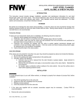
1.2 Valve construction
Series GW valves are flanged (weld end available) 3-way
sliding stem control valves. Two seat rings and the plug
with stem is a module accessible through the bottom bon-
net opening (bottom entry) of the body.
GW valves are available both diverting and mixing flow for
a most primary application is in temperature control.
Our standard design combines the benefits of more strong
guiding with a top and bottom seat rings, and the solid cylin-
drical plug makes strong support to ensure valve alignment.
GW valves are available both cylindrical and V-port plug trim
depending from the application, standard is cylindrical plug.
This series are available to provide a series of reduced trim
and the standard seat tightness is class II, optional trims can
meet to class III and IV, ANSI/FCI 70.2.
The detailed structure is revealed by the type code shown
on the valve identification plate. The type code is explained
in Section 11.
1.3 Valve markings
The body markings are: manufacturer's trademark, nominal
size, pressure rating and material of the body. The valve has
an identification plate attached to it, see Fig. 2.
Markings on the identification plate:
1. Type designation (Valve code)
2. Size, Rating
3. Cv
4. Body material
5. Plug, Stem material
6. Seat material
7. Temp. min./max.
8. Maximum (shut-off) pressure
9. Valve manufacturing date
10. Tag No.
11. Serial No.
NOTE:
Selection and use of the valve in a specific application
requires close consideration of detailed aspects. Due to the
nature of the product, this manual cannot cover all the indi-
vidual situations that may occur when the valve is used.
If you are uncertain about use of the valve or its suitability
for your intended purpose, please contact Metso Automa-
tion for more information.
Fig. 1 Construction of the Neles GW series 3-way Valve
Mixing type
Diverting type
Fig. 2 Identification(name) plate example

4 4 GV 74 en
1.4 Technical specifications
Face-to-face length: ANSI/ISA-75.08.01, 03, 05 &
ANSI/ISA-75.08.06 (Long)
Body rating: Class 150 to Class 600
PN 10 to PN 40
Max. pressure differential:
acc. to pressure class
Temperature range: -30° to +450 °C (depending on the
body materials and bonnet type)
Flow direction: indicated by an arrow on the body
Actuator mounting: threaded bonnet with yoke nut or
bolted yoke
Stem connection: clamp with bolts/nuts
Dimensions: see Section 10
Weights: see Section 10
Note that the max. shut-off pressure is based on the mechan-
ical maximum differential pressure at ambient temperature.
You must always observe the fluid temperature when decid-
ing on applicable pressure values. When selecting a valve
you must also check the noise level, cavitation intensity, flow
velocity, actuator load factor, etc. using Nelprof.
1.5 Valve seat leakage class
The valve follows the seat leakage classifications of ANSI/
FCI 70-2 requirement.
1.6 Recycling and disposal
Most valve parts can be recycled if sorted according to
material. Most parts have a material marking. A material list
is supplied with the valve. In addition, separate recycling
and disposal instructions are available from the manufac-
turer. A valve can also be returned to the manufacturer for
recycling and disposal for a fee.
1.7 Safety precautions
2 TRANSPORTATION, RECEPTION AND
STORAGE
Check the valve and the accompanying devices for any
damage that may have occurred during transport.
Store the valve carefully before installation, preferably
indoors in a dry place.
CAUTION:
Do not exceed the valve performance limitations!
Exceeding the limitations marked on the valve may cause
damage and lead to uncontrolled pressure release. Dam-
age or personal injury may result.
CAUTION:
Do not dismantle the valve or remove it from the pipe-
line while the valve is pressurised!
Dismantling or removing a pressurised valve will result in
uncontrolled pressure release. Always isolate the relevant
part of the pipeline, release the pressure from the valve
and remove the medium before dismantling the valve.
Be aware of the type of medium involved. Protect yourself
and the environment from any harmful or poisonous sub-
stances. Make sure that no medium can enter the pipeline
during valve maintenance.
Failure to do this may result in damage or personal injury.
CAUTION:
Beware of the plug movement!
Keep fingers, other parts of the body, tools and other
objects out of the open flow port. Leave no foreign
objects inside the pipeline. When the valve is actuated,
the plug functions as a cutting device. Close and detach
the actuator pressure supply pipeline for valve mainte-
nance. Failure to do this may result in damage or personal
injury.
CAUTION:
Protect yourself from noise!
The valve may produce noise in the pipeline. The noise
level depends on the application. It can be measured or
calculated using the Metso Nelprof software. Observe the
relevant working environment regulations in terms of
noise emission.
CAUTION:
Beware of a very cold or hot valve!
The valve body may be very cold or very hot during use.
Protect yourself against cold injuries or burns.
CAUTION:
When handling the valve or the control valve assem-
bly, take its weight into account!
Never lift the valve or control valve assembly by the posi-
tioner, the limit switch or their piping.
Place the lifting ropes securely around the valve body (see
Fig. 3). Damage or personal injury may result from falling
parts.
Fig. 3 Lifting the valve

4 GV 74 en 5
Do not remove the flow port protectors until immediately
before installation of the valve into the pipeline.
The valve is delivered in the closed position. A valve
equipped with a spring-return actuator is delivered in the
position determined by the spring.
3 VALVE INSTALLATION
3.1 General
Remove the flow port protectors and check that the valve is
clean inside.
3.2 Installation into the pipeline
Make sure no foreign particles, such as sand or pieces of
welding electrode, are in the pipeline, they may damage
the sealing surfaces.
The valve has an arrow indicating the flow direction. Install
the valve in the pipeline so that the flow direction of the
valve corresponds to the flow direction marked on the pipe.
The mounting orientation of the valve does not restrict the
operation of the valve, actuator or positioner. You should,
however, avoid installing the valve so that the shaft points
downwards as impurities in the fluid may enter and dam-
age the gland packing. Any leak from the packing may then
damage the actuator. See Fig. 6.
Choose flange gaskets according to the operating condi-
tions.
Do not attempt to correct a pipeline misalignment by
means of flange bolting.
Loads on the valve body from pipeline vibrations can be
reduced by supporting the pipeline properly. Reduced
vibration also increases the lifetime of the positioner.
Where necessary, you can support the valve by the body,
using regular pipe clamps and supports. Do not fasten sup-
ports to the valve or flange bolting or to the actuator, see
Fig. 4.
3.3 Control valve assembly
Check all joints, piping and cables.
Check that the actuator stop screws, positioner and limit
switches are calibrated. Refer to their installation, mainte-
nance and operating manuals.
3.4 Valve insulation
If necessary, the valve may be insulated. Insulation must not
continue above the upper level of the valve body, see Fig. 5.
4 MAINTENANCE
4.1 General
The Neles series GW 3-way valves require no regular main-
tenance. However, check the gland packing for leakage.
This section outlines the maintenance that can be carried
out by the user.
The numbers in parentheses refer to the parts lists and the
exploded views of the valve in Section 9.
CAUTION:
When handling the valve or the control valve assem-
bly, take its weight into account!
Fig. 4 Installing the control valve into pipeline using
supports
Fig. 5 Insulation of the valve
CAUTION:
Observe the safety precautions listed in Section 1.7
before starting work!
CAUTION:
When handling the valve or the control valve assem-
bly, take its weight into account!
NOTE:
If you send the valve to the manufacturer for repair, do not
dismantle it. Clean the valve carefully, including the inside.
For safety reasons, inform the manufacturer of the nature
of the medium when you send the valve.
NOTE:
Always use original spare parts to make sure the valve
functions as intended.

6 4 GV 74 en
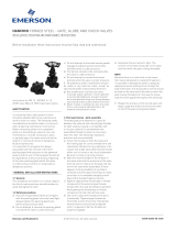
4.2 Gland packing adjustment
In the event of a packing leakage tighten the hexagon nuts
(18) in ¼ turn steps each until the leakage is stopped. Do
not tighten more than necessary.
4.3 Replacing the gland packing
Make sure the valve is not pressurised.
Remove the actuator from the valve stem according
to the instructions given in the actuator manual.
Loosen and remove the hexagon nuts (18).
Remove the gland flange (9b), and gland (9a) up to
the valve stem.
Remove the old packing rings (69) using a pointed
tool, avoid damaging the seal surfaces and valve
stem.
Clean the packing ring counterbore.
Mount the new packing rings one by one into the
packing gland box using the gland as a tool and
mount the gland with hand-tightened nuts.
Fasten the gland with the hexagon nuts (18) and
tighten them.
Check leakage when the valve is pressurised.
Table 1 Required torques for bonnet nuts
4.4 Replacing the trim and body
reassembly
Make sure the valve is not pressurised.
Remove the actuator from the valve stem according
to the instructions given in the actuator manual and
next Section 6.
Turn the body (1) and remove the bottom hexagon
nuts (17).
Remove the bottom flange (26).
Remove the body gasket (65).
Remove the stem (5) and plug (3) sub-assembly.
Avoid from damaging the seating and guiding line
of the plug.
Remove the each two seat rings (7 & 7a) from body
(1) and bottom flange (26) using by fabricated
wrenches to be engaged the seat ring lugs and
adapted to shock wrench.
This is threaded type, if the seat ring is extremely
resistance to removal, the application of heat or pen-
etrating oil will be helpful.
Remove the hexagon nuts (18), gland flange (9b)
and packing gland (9a) from the bonnet (8).
Remove the old packing rings (69).
CAUTION:
Do not dismantle the valve or remove it from the pipe-
line while the valve is pressurised.
Fig. 6 Gland packing
Valve Size
Rating
(ANSI)
Bonnet Stud Bolts
Required Torques
(± 5 % allowable)
mm in Size Q`ty
Carbon Steel
Bolts
St. Steel Bolts
Nm lbf ft Nm lbf ft
25 1
150-300 1/2"-13UNC 4
44 32 35 26
600 1/2"-13UNC 4
40 1.5
150-300 1/2"-13UNC 4
61 45 49 36
600 1/2"-13UNC 4
50 2
150-300 1/2"-13UNC 8 101 74 80 59
600 1/2"-13UNC 8 158 116 123 90
80 3
150-300 3/4"-10UNC 8 176 129
136 100
600 3/4"-10UNC 8 211 155
100 4
150-300 7/8"-9UNC 8 222 163
160 118
600 7/8"-9UNC 8 327 240
150 6
150-300 1"-8UNC 8 316 232
291 214
600 1"-8UNC 12 327 240
200 8
150-300 1-1/4"-8UNC 8 478 351 478 351
600 1-1/4"-8UNC 12 653 479 653 479
250 10
150-300 1-1/4"-8UNC 12 486 356 486 356
600 1-1/4"-8UNC 16 909 667 716 525
Fig. 7 Tightening sequence of the bonnet nuts
NOTE:
The trim set consists of the seat rings, valve plug and stem,
gaskets (for body).
CAUTION:
If using heating devices, insure that proper safety
practices are observed. Such items as the flammability
and toxicity of the controlled substance must be consi-
dered and proper precautions and permissions taken.

4 GV 74 en 7
Clean the body gasket surface.
Insert and tighten the each new top and bottom seat
rings (7 & 7a) into the body (1) and bottom flange
(26).
Insert the stem (5) & plug (3) sub-assembly from top
side into the body very carefully.
Insert the body gasket (65) into bottom side of the
body.
Mount the bottom flange (26) on the body carefully
maintaining alignment with the plug and stem in
the closed
position, so that the arrow on the body and on the
bonnet point in the same direction.
Insert the hexagon nuts (17) into stud (13) and
slightly fasten the nuts.
Insert the packing rings (69) according to above 4.3
Tighten hexagon nuts (17) until plug and seat con-
tact is obtained with proper bolt torque.
5 TESTING THE VALVE
We recommend that the valve body is pressure-tested after
the valve has been assembled.
The pressure test should be carried out in accordance with
an applicable standard for the pressure rating. The valve
must be in the open position during the test.
CAUTION:
Do not strongly tighten hexagon nuts (17) at this time.
CAUTION:
Do not reuse the spiral wound gaskets (65), this is
need to be replace each time the valve is disassemb-
led.
CAUTION:
The all related parts (seat ring, plug & stem, bonnet)
must be properly aligned in the body.
NOTE:
If the valve have excess leakage, the plug and seating sur-
face need lapping and cleaning.
Fig. 8 Conventional Cylindrical Plug Trim
Fig. 9 Different trim designs
Cylindrical plug trim V-port plug trim
CAUTION:
Pressure testing should be carried out using equip-
ment conforming to the correct pressure class!

8 4 GV 74 en
6 REMOVAL & MOUNTING THE
ACTUATOR
The actuator is attached to the valve according to the manual
for actuator with body assembly and plug stem adjustment .
Several types of Metso actuators can be used with suitable
clamps. Refer to the model VD spring-diaphragm and VC
double acting cylinder actuator manuals for further informa-
tion on their installation, maintenance and operation.
A. Actuator removal for Reverse <air to top seat close,
stem retract> actuator (Fig. 10)
Lift up to the valve plug 100% from the seat ring,
using by specified air pressure.
Loosen the stem locknut and socket head screws
(27) and hexagon nuts(28).
Remove the clamp (26).
Shut off and disconnect air supply line.
Support actuator with the suitable lifting device.
Remove the yoke nut.
Remove the actuator from the valve body assembly.
B. Actuator replacement (mounting) for Reverse <air to
top seat close, stem retract> actuator (Fig. 10)
Mount the new or repaired actuator on top of the
bonnet, using a suitable lifting device.
Insert the yoke nut and tightly fasten the yoke by
turning the yoke nut clockwise using tightening
tools.
Connect air line and accessories.
Lift the top stem (18), using by specified air pressure.
Adjustment stem length after clamping the clamp
(26) according to rated travel(stroke) as ‘open’ and
‘close’ position as per pressurizing and depressuriz-
ing the lower diaphragm chamber.
Tighten stem socket head screws (27) and hexagon
nuts (28) with stem locknut.
C. Actuator removal for Direct <air to bottom seat
close, stem extend> actuator (Fig. 10)
Shut off and disconnect the air supply lines and
accessories.
Loosen stem locknut and socket head screws (27)
and hexagon nuts (28).
Remove the clamp (26).
Support actuator with the suitable lifting device.
Remove the yoke nut.
Remove the actuator from the valve body assembly.
D. Actuator replacement (mounting) for Direct <air to
bottom seat close, stem extend> actuator (Fig. 10)
Mount the new or repaired actuator on top of the
bonnet, using a suitable lifting device to setting.
Insert the yoke nut and tightly fasten the yoke by
turning the yoke nut clockwise using tightening
tools.
Connect air line and accessories.
Down the top stem (18), using by specified air pres-
sure.
Adjust stem length after clamping the clamp accord-
ing to rated travel (stroke) as ‘open’ and ‘close’ posi-
tion as per pressurizing and depressurizing the
upper diaphragm chamber.
Tighten socket head screws (27) and hexagon nuts
(28) with stem locknut.
E. Type ‘VC’ Springless Cylinder, Double Acting Actuator
This actuator is springless cylinder, double acting actuator,
can use the 3/8”, 1/2” NPT port according to specified on the
data sheet for all air lines.
Refer to the model VC double acting cylinder actuator man-
uals for further information on their installation, mainte-
nance and operation.
CAUTION:
Beware of the plug movement!
Do not use air pressure higher than what specified on the
identification plate.
CAUTION:
Avoid to turn the valve plug and stem when plug is on
seat ring to prevent the seating line from being dama-
ged.
Fig. 10 VD Actuator
͵ΚΣΖΔΥ͑ͲΔΥΚΠΟ͑ΒΔΥΦΒΥΠΣ
͙ͲΚΣ͑ΥΠ͑ʹΝΠΤΖ͝ΤΥΖΞ͑ΖΩΥΖΟΕ͚
ΖΧΖΣΤΖ͑ͲΔΥΚΠΟ͑ΒΔΥΦΒΥΠΣ
͙ͲΚΣ͑ΥΠ͑ΡΖΟ͝ΤΥΖΞ͑ΣΖΥΣΒΔΥ͚

4 GV 74 en 9
7TOOLS
Removal of the actuator
L- wrench set (mm)
Hex. socket wrench set
Chisel and hammer (10 pound)
+,- drivers
8 ORDERING SPARE PARTS
When ordering spare parts, always include the following
information:
type code, sales order number, serial number
number of the parts list, part number, name of the
part and quantity required
This information can be found from the identification plate
or documents.
NOTE:
Always use original spare parts to make sure that the valve
functions as intended.

10 4 GV 74 en
9 EXPLODED VIEW AND PARTS LIST
Item Description Recommended spare part
1BODY
3* PLUG
5* STEM
6* PLUG PIN
7SEAT RING
7a SEAT RING
8BONNET
9a GLAND
9b GLAND FLANGE
11 YOKE NUT
13 STUD
14 STUD
17 HEXAGON NUT
18 HEXAGON NUT
21 LANTERN RING
22** PACKING SPRING
26 BOTTOM FLANGE
30 HEXAGON SCREW
30a WASHER
30b SPRING WASHER
65 BODY GASKET X
67 PACKING SPACER
69** V-RING SET X
69 PACKING RING X
86 FLOW DIRECTION ARROW
*) Delivered as a set
**) Packing type of V-Ring set

4 GV 74 en 11
10 DIMENSIONS AND WEIGHTS
10.1 Valve GW
150 # / 300 # / 600 #
(UNIT: mm)
Dimension
Size
ABCDEFGHWeight (kg)
150# 300# 600# 150# 300# 600# STD EXT
COMMON
150# 300# 600# 150# 300# 600# 150# 300# 600# 150# 300# 600# 150# 300# 600#
1" 184 197 210 140 140 140 142 250 110 110 125 125 15.9 19.1 19.1 79.4 88.9 88.9 4 4 4 20 21 33
1-1/2" 222 235 251 178 178 178 155 295 110 125 155 155 15.9 22.2 22.2 98.4 114.3 114.3 4 4 4 41 43 50
2" 254 267 286 197 197 197 184 295 110 150 165 165 19.1 19.1 19.1 120.7 127 127 4 8 8 57 62 73
3" 298 318 337 238 238 251 235 330 115 190 210 210 19.1 22.2 22.2 152.4 168.3 168.3 4 8 8 100 104 113
4" 352 368 394 270 270 282 238 380 140 230 255 275 19.1 22.2 25.4 190.5 200 215.9 8 8 8 136 141 156
6" 451 473 508 330 330 356 321 430 150 280 320 355 22.2 22.2 28.6 241.3 269.9 292.1 8 12 12 238 249 322
8" 543 568 610 391 391 416 375 490 150 345 380 420 22.2 25.4 31.8 298.5 330.2 349.2 8 12 12 351 375 451
10" 625 708 752 457 457 490 416 600 150 405 445 510 25.4 28.6 34.9 362 387.4 431.8 12 16 16 779 847 982

12 4 GV 74 en
10.2 Actuators VD, VC
(UNIT: mm)
Size A2
Bd
C2 D
Ed
Weight (kg)
Br Er
#25 255
333
210 NPT 1/4
134
10
358 113
#29 295
370
231 NPT 1/4
144
19
397 113
#37 375
450
269 NPT 1/4
161
37
475 114
#48 486
632
361 NPT 1/4
205
92
654 141
#55 566
675
361 NPT 1/4
242
116
700 141
1. "Br" & "Er" refers to reverse acting actuator, VDR 2. "Bd" & "Ed" refers to direct acting actuator, VDD
(UNIT: mm)
Size A2
Bd
C2 D
Ed Fd
Weight (kg)
Br Er Fr
#25 255
473
210 NPT 1/4
134 141
13
440 113 105
#29 295
576
231 NPT 1/4
144 183
25
529 113 157
#37 375
660
269 NPT 1/4
161 186
46
614 114 158
1. "Br" & "Er" refers to reverse acting actuator, VDR 2. "Bd" & "Ed" refers to direct acting actuator, VDD

4 GV 74 en 13
(UNIT: mm)
Size A2
Bd
C2 D
Ed
A3 Gh Bh Weight (kg)
Br Er
#48 486
1053
361 NPT 1/4
205
335 420 847 112
1053 141
#55 566
1106
361 NPT 1/4
242
335 420 915 145
1106 141
1. "Br" & "Er" refers to reverse acting actuator, VDR 2. "Bd" & "Ed" refers to direct acting actuator, VDD

14 4 GV 74 en
Size # 30
(UNIT: mm)
Stroke A
B1
ØC
D1
E F
Weight (kg)
B2 D2 A B
40 145
590
Ø370
175
420 NPT 3/8 92 116
680 285
50 145
610
Ø370
185
420 NPT 3/8 97 122
700 305
70 145
650
Ø370
205
420 NPT 3/8 102 128
740 345
80 145
670
Ø370
215
420 NPT 3/8 107 134
760 365
100 145
710
Ø370
235
420 NPT 3/8 113 141
800 405
120 145
750
Ø370
255
420 NPT 3/8 119 147
840 445
Size # 40
(UNIT: mm)
Stroke A
B1
ØC
D1
E F
Weight (kg)
B2 D2 A B
40 145
625
Ø460
195
560 NPT 1/2 118 149
920 320
50 145
645
Ø460
205
560 NPT 1/2 123 156
940 340
70 145
685
Ø460
225
560 NPT 1/2 127 160
950 380
80 145
705
Ø460
235
560 NPT 1/2 132 166
970 400
100 145
745
Ø460
255
560 NPT 1/2 135 170
1010 440
120 145
785
Ø460
275
560 NPT 1/2 139 175
1030 480
150 145
845
Ø460
305
560 NPT 1/2 144 181
1090 540
160 145
865
Ø460
315
560 NPT 1/2 148 186
1110 560
170 145
885
Ø460
325
560 NPT 1/2 155 194
1130 580
180 145
905
Ø460
335
560 NPT 1/2 159 199
1150 600
Size # 50
(UNIT: mm)
Stroke A
B1
ØC
D1
E F
Weight (kg)
B2 D2 A B
40 145
625
Ø560
195
560 NPT 1/2 150 188
920 320
50 145
645
Ø560
205
560 NPT 1/2 156 195
940 340
70 145
685
Ø560
225
560 NPT 1/2 162 202
950 380
80 145
705
Ø560
235
560 NPT 1/2 168 210
970 400
100 145
745
Ø560
255
560 NPT 1/2 175 218
1010 440
120 145
785
Ø560
275
560 NPT 1/2 181 226
1030 480
150 145
845
Ø560
305
560 NPT 1/2 188 233
1090 540
160 145
865
Ø560
315
560 NPT 1/2 195 242
1110 560
170 145
885
Ø560
325
560 NPT 1/2 202 250
1130 580
180 145
905
Ø560
335
560 NPT 1/2 209 259
1150 600

4 GV 74 en 15
Size # 30
(UNIT: mm)
Stroke A
B1
ØC
D1
E F G
Weight (kg)
B2 D2 A B
40 145
910
Ø370
175
705 470 NPT 3/8 120 144
1020 285
50 145
920
Ø370
185
705 470 NPT 3/8 125 150
1040 305
70 145
940
Ø370
205
705 470 NPT 3/8 130 156
1080 345
80 145
950
Ø370
215
705 470 NPT 3/8 135 162
1100 365
100 145
970
Ø370
235
705 470 NPT 3/8 141 169
1140 405
120 145
990
Ø370
255
705 470 NPT 3/8 147 175
1180 445
Size # 40
(UNIT: mm)
Stroke A
B1
ØC
D1
E F G
Weight (kg)
B2 D2 A B
40 145
1080
Ø460
195
850 620 NPT 1/2 158 189
1210 320
50 145
1090
Ø460
205
850 620 NPT 1/2 163 196
1230 340
70 145
1110
Ø460
225
850 620 NPT 1/2 167 200
1270 380
80 145
1120
Ø460
235
850 620 NPT 1/2 172 206
1290 400
100 145
1140
Ø460
255
850 620 NPT 1/2 175 210
1330 440
120 145
1160
Ø460
275
850 620 NPT 1/2 179 215
1370 480
150 145
1190
Ø460
305
850 620 NPT 1/2 184 221
1430 540
160 145
1200
Ø460
315
850 620 NPT 1/2 188 226
1450 560
170 145
1210
Ø460
325
850 620 NPT 1/2 195 234
1470 580
180 145
1220
Ø460
335
850 620 NPT 1/2 199 239
1490 600
Size # 50
(UNIT: mm)
Stroke A
B1
ØC
D1
EF G
Weight (kg)
B2 D2 A B
40 145
1080
Ø560
195
850 620 NPT 1/2 190 228
1210 320
50 145
1090
Ø560
205
850 620 NPT 1/2 196 235
1230 340
70 145
1110
Ø560
225
850 620 NPT 1/2 202 242
1270 380
80 145
1120
Ø560
235
850 620 NPT 1/2 208 250
1290 400
100 145
1140
Ø560
255
850 620 NPT 1/2 215 258
1330 440
120 145
1160
Ø560
275
850 620 NPT 1/2 221 266
1370 480
150 145
1190
Ø560
305
850 620 NPT 1/2 228 273
1430 540
160 145
1200
Ø560
315
850 620 NPT 1/2 235 282
1450 560
170 145
1210
Ø560
325
850 620 NPT 1/2 242 290
1470 580
180 145
1220
Ø560
335
850 620 NPT 1/2 249 299
1490 600

Metso Automation Inc.
Europe, Vanha Porvoontie 229, P.O. Box 304, FI-01301 Vantaa, Finland. Tel. +358 20 483 150. Fax +358 20 483 151
North America, 44 Bowditch Drive, P.O. Box 8044, Shrewsbury, MA 01545, USA. Tel. +1 508 852 0200. Fax +1 508 852 8172
Asia Pacific, 20 Kallang Avenue, Lobby B, #06-00, PICO Creative Centre, Singapore 339411, Singapore. Tel. +65 6511 1011. Fax +65 6250 0830
China, 19/F, the Exchange Beijing, No. 118, Jianguo Lu Yi, Chaoyang Dist, 100022 Beijing, China. Tel. +86-10-6566-6600. Fax +86-10-6566-2575
Middle East, Roundabout 8, Unit AB-07, P.O. Box 17175, Jebel Ali Freezone, Dubai, United Arab Emirates. Tel. +971 4 883 6974. Fax +971 4 883 6836
www.metso.com/valves
South America, Av. Independéncia, 2500-Iporanga, 18087-101, Sorocaba-São Paulo, Brazil. Tel. +55 15 2102 9700. Fax +55 15 2102 9748
Metso Automation Inc.
South Korea, 127, Jungwonsaneom-ro, Judeok-eup, Chungju-si, Chungbuk-do, Korea. #380-881. Tel. +82 43 852 7708 Fax. +82 43 852 7818
16 4 GV 74 en
11 TYPE CODE
Globe 3-Way, Diverting / Mixing type, Series GW
1. 2. 3. 4. 5. 6. 7. 8. 9. 10. 11. 12. 13. 14. 15. 16. 17. 18. 19. 20. 21. 22.
GW 02 C W A J2 X P1 X BC S2 P1 X S F X S A X A L FC
1. VALVE SERIES
GW Globe 3-way, Diverting type
2. BODY SIZE
01 1
" / DN 25 1H 1-1/2" / DN 40
02 2
" / DN 50 03 3" / DN 80
04 4
" / DN 100 06 6" / DN 150
08 8
" / DN 200 10 10" / DN 250
YY Special
3. PRESSURE RATING
C ASME class 150 D ASME class 300
Optional Pressure Rating
F ASME class 600 Y Special
4. END CONNECTION
W Flanged RF, ASME B16.5
Optional End Connection
V Socket welding, ASME B16.11
Q Butt welding, ASME B16.25
Y Special
5.
BONNET CONSTRUCTION
Bonnet type Actuator Connection
A Standard Standard actuator size
B Standard Applicable for VD_48/55 (3",4" only)
Optional Bonnet Construction
E Extension Standard actuator size
F Extension Applicable for VD_48/55 (3",4" only)
Y Special Special
6. BODY & BONNET MATERIAL
J2 A216 gr. WCB S6 A351 gr. CF8M
Optional Body & Bonnet Material
S4 A351 gr. CF8 S9 A351 gr. CF3
S1 A351 gr. CF3M YY Special
7. BEARINGS (TRUNNION / THRUST BEARING)
X Not applicable Y Special
8.
PLUG MATERIAL
Material Description
P1 410 SS Standard for carbon steel body
T6 316 SS Standard for stainless steel body
YY Special Special materials
9. PLUG APPLICATION
X Not applicable
A Cobalt based alloy
Y Special
10.
STEM MATERIAL
Material Description
BC 630 SS + HCr Standard for carbon steel body
TC 316 SS + HCr Standard for stainless steel body
YY Special Special materials
11. SEAT TYPE
S2 Double metal seat
YY Special
12.
SEAT MATERIAL
Seat Description
P1 410 SS Standard for carbon steel body
T6 316 SS Standard for stainless steel body
YY Special Special materials
13. SEAT APPLICATION
X Not applicable
A Cobalt based alloy
Y Special
14. PACKING TYPE
S Standard packing
Optional Packing Type
L Live loaded packing
B Bellows seal
Y Special
15. PACKING MATERIAL
F Graphite (with mold and braided)
T PTFE V-Ring
Optional Packing Material
G PTFE + Carbon fiber
Y Special
16. SEALS MATERIAL
X Not applicable Y Special
17. GASKET MATERIAL
S S/W gasket type, 316 SS + Graphite for standard
Optional Gasket Material
H S/W gasket type, 316 SS + Graphite for high temp.
L S/W gasket type, 316 SS + PTFE
Y Special
18. STUD / NUT MATERIAL
A A193 gr. B7 / A194 gr. 2H
B A193 gr. B8 / A194 gr. 8
Y Special
19. OPTIONS
X Not Applicable
M Globe 3-Way, Mixing type
Y Special
20.
TRIM TYPE
21.
TRIM
CHARACTERISTIC
22. RATED Cv
Sign Sign Sign Description
Body Size
1" Srk. 1-1/2" Srk. 2" Srk. 3" Srk. 4" Srk. 6" Srk. 8" Srk. 10" Srk.
A Cylindrical plug type L Linear FC Full capacity 10 (15) 22 (20) 36 (30) 76 (40) 126 (50) 274 (60) 490 (70) 760 (70)
V V-port plug type Q Quick-Opening 1A Reduced trim 4 (15) 10 (20) 16 (30) 36 (40) 62 (50) 135 (60) 240 (70) 360 (70)
Y Special trim type Y Special YY Special Contact Metso Automation for Cv details
* Rated Cv is separeted depending on the trim type & trim characteristic. * Srk. & number in the bracket means the valve stroke.
/