Klipsch RSA-500-BL Owner's manual
- Category
- Subwoofers
- Type
- Owner's manual
This manual is also suitable for
Page is loading ...

IMPORTANT SAFETY INSTRUCTIONS
1. READ these instructions.
2. KEEP these instructions.
3. HEED all warnings.
4. FOLLOW all instructions.
5. DO NOT use this apparatus near water.
6. CLEAN ONLY with dry cloth.
7. DO NOT block any ventilation openings. Install in accordance
with the manufacturer's instructions.
8. DO NOT install near any heat sources such as radiators, heat
registers, stoves, or other apparatus (including amplifiers) that
produce heat.
9. DO NOT defeat the safety purpose of the polarized or grounding
type plug. A polarized plug has two blades with one wider than
the other. A grounding type plug has two blades and a third
grounding prong. The wider blade or the third prong are provided
for your safety. If the provided plug does not fit into your outlet,
consult an electrician for replacement of the obsolete outlet.
10. PROTECT the power cord from being walked on or pinched,
particularly at plugs, convenience receptacles, and the point
where they exit from the apparatus.
11. ONLY USE attachments/accessories specified by the
manufacturer.
12. USE only with a cart, stand, tripod, bracket, or table specified
by the manufacturer, or sold with the apparatus. When a cart is
used, use caution when moving the cart/apparatus
combination to avoid injury from tip-over.
13. UNPLUG this apparatus during lightning storms or when unused
for long periods of time.
14. REFER all servicing to qualified service personnel. Servicing is
required when the apparatus has been damaged in any way,
such as power-supply cord or plug is damaged, liquid has been
spilled or objects have fallen into the apparatus, the apparatus
has been exposed to rain or moisture, does not operate
normally, or has been dropped.
15. Do not expose this apparatus to dripping or splashing and
ensure that no objects filled with liquides, such as vases, are
placed on the apparatus.
16. To completely disconnect this apparatus from teh AC Mains,
disconnect the power supply cord plug from the AC receptacle.
17. The mains plug of the power supply cord shall remain readily
operable.
This symbol indicates that there are important
operating and maintenance instructions in the
literature accompanying this unit.
This symbol indicates that dangerous voltage
constituting a risk of electric shock is present within
this unit.
WARNING: To reduce the risk of fire or electrical shock, do not
expose this a
pparatus to rain or moisture.
WARNING: Voltages in this equipment are hazardous to life.
No user
-serviceable parts inside. Refer all servicing to qualified
service personnel.
CAUTION: Changes or modifications not expressly approved by the
manufacturer could void the user’
s authority to operate this device.
ABOUT YOUR KLIPSCH PURCHASE
Thank you for your purchase of a Klipsch subwoofer amplifier.
After reading this manual and connecting your system,
you will
hear the results of over 60 years of stringent engineering and
class-leading research and development. Again, thank you for
choosing Klipsch and we hope that your subwoofer amplifier
brings life to your music and movies for many years.
UNPACKING
The easiest way to remove the amplifier from its carton is to turn
the open end of the box down so tha
t it is resting on a table or
the floor, with the flaps spread out and away. Then pull the box
straight up and off. Remove any packing material from the
amplifier, place it back in the carton, and store in case you ever
need to ship the amplifier.
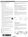
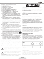
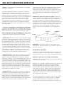
FRONT PANEL CONTROLS
1. Lowpass Crossover
The Lowpass Crossover control allows you to select the proper
frequency a
t which your subwoofer system blends with your
main speakers. It is adjustable from 40-120Hz. You should set
this control to the approximate low-frequency limit of your main
left and right speakers.
2. Level Control
The Level control is the volume setting for the amplifier. It is used
in conjunction with the subwoofer output level control on your
preamplifier or receiver
. It is used to adjust the overall output
level of your subwoofer system.
RSA-500 SUBWOOFER AMPLIFIER
English
Figure 1
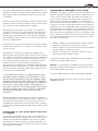
Figure 2

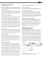
REAR PANEL INPUTS AND OUTPUTS
/CONNECTIONS AND SETUP
Make all connections with the power turned “OFF” on both
the subw
oofer amplifier and your receiver or preamplifier!
1. Speaker Level Inputs
The Speaker Level inputs which allow this amplifier to be used in
whole house distributed audio systems or with receivers tha
t do
not feature line or subwoofer outputs. You may connect either
the inputs or outputs with Banana or pin connectors as well as
stripped wire up to 12 gauge.
2. Line Level Inputs and Outputs
The Line Level inputs consists of a pair of stereo jacks and a
single LFE RCA phono jack.
Either one or both of the stereo jacks
may be used. (Use a shielded, high quality subwoofer
interconnect cable of appropriate length with RCA plugs on each
end. Your dealer can help you select a suitable cable.) Use
the LFE jack when you are using the crossover built into your
receiver or processor. The stereo inputs should be used when
you wish to utilize the crossover built into the RSA-500. The Line
Level outputs consist of a pair of gold plated stereo RCA jacks
and a single LFE RCA phono jack. This set of outputs are unfil-
tered pass through for both the Line Level and LFE input signals.
They can be used to connect to a second RSA-500 amplifier or
to connect back to your electronics if needed.
3. Phase Control
The Phase control on the RSA-500 is switchable between either
0˚ or 180˚.
This control allows you to fine tune the performance
of your subwoofer system by optimizing the blend with the main
speakers. One of the positions may result in an audible increase
in bass output depending upon room placement.
4. Equalizer Selection
The Equalizer switch has four settings which are labeled 1
through 4.
In the “1” position, the EQ curve selected is opti-
mized for the RW-5802 in-wall subwoofer. In the “2” position,
the EQ curve selected is optimized for the AW-800-SW outdoor
subwoofer. In the “3” position, the EQ curve selected is
optomized for the RW-5101-C in-ceiling subwoofer. The position
labeled “4” is for future use.
5. Power Mode Selection
The Power Mode switch has three settings – “Trigger”, “Auto”
and“On”.
In the “Trigger” position, leave the Master Power switch
in the “On” position and set the Power Mode switch to the
“Trigger” position, then the amplifier will automatically turn itself
on and off when 5-30 volts DC is detected or removed from the
rear panel 1/8" Trigger jack. Tip is positive, ring is negative.
There is no delay when using the Trigger function. In the “Auto”
position, leave the Master Power switch in the “On” position and
set the Power Mode switch to the “Auto” position, then the
amplifier will automatically turn itself on and off when an audio
signal is detected or removed from the rear low or high level
inputs. There is a 2 second On delay and a 15 minute Off delay
when using the Auto Power function. In the “On” position, the
Master Power switch turns the amplifier on or off. Set the Master
Power switch to the “On” position and set the Power Mode
switch to the “On” position, then the amplifier will turn itself on
and off with the Master Power switch.
6. Speaker Level Outputs
The Speaker Level outputs may connected either with Banana or
pin connectors as well as stripped wire up to 12 gauge.
7. AC Line Cord and Main Switch
The AC Line connection uses a detachable two-prong power
cord.
Insert the line cord into this jack, set the Master Power
switch located above the cord to “Off”, then insert the power
cord into an appropriate AC receptacle. Leave the Master Power
switch off until all connections are completed. (We recommend
leaving the Master Power and Power Mode switches in the “On”
position for normal operation in most systems.)
CONNECTIONS AND ADJUSTMENTS
The RSA-500 is a high-performance, power amplifier with a
built-in subwoofer crossover
. It is designed specifically to drive
one or two subwoofer modules, such as the RW-5802, to maxi-
mum output without audible distortion or risk of damage.
Although the amplifier’s connections and controls are simple,
their use varies somewhat according to the subwoofer system’s
application. Typical setup procedures are described in the
following sections – one for digital systems and one for
analog systems.
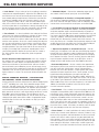
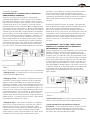
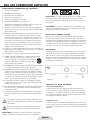
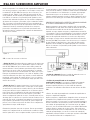
DIGITAL SURROUND RECEIVER OR
PR
OCESSOR CONNECTIONS
Today’s Dolby Digital
®
and DTS
®
digital surround receivers and
processors, as well as all THX-certified models, have line-level
subwoofer outputs and built-in subwoofer crossovers. If your
system is built around one of these, it will almost always be best
to use the RSA-500’s LFE input. This will bypass the crossover
and level controls (Figure 3). Use a shielded, high quality sub-
woofer interconnect cable of appropriate length with RCA plugs
on each end. Your dealer can help you select a suitable cable. Be
sure to go into your receiver or processor’s speaker setup menu
and set Subwoofer to “On” or “Yes” in the subwoofer menu. Your
receiver or processor may have additional bass management
abilities beyond simply activating the subwoofer output. Consult
your receiver or processor’s owner’s manual or your dealer for
more information on the proper bass management settings for
your system.
• Crossover Adjustment – When the RSA-500’s LFE input is
used,
the crossover control will not function.
Figure 3

• Level Control – Play a variety of music recordings containing
strong but not overpowering bass. Adjust the RSA-500 level con-
trol until the music sounds consistently warm and natural. If you
have trouble getting enough low bass without the sound becom-
ing boomy, it probably means the Crossover control is set too
high. Try turning it down a bit at a time until the problem goes
away. If the sound is thin until you turn the subwoofer Level up so
much that lower bass is too prominent, start by changing the set-
ting of the Phase control. If that does not entirely solve the prob-
lem, you probably need to raise the Crossover frequency.
• Phase Control – In some installations the setting of the Phase
control ma
y not make much difference, whereas in others it may
be necessary to go back and forth between the Phase
and Level controls for a while in order to get the very best blend
with the main speakers. Since each control setting (including the
one for crossover frequency in the receiver or processor) affects
the optimum settings for the others, it often takes a while to get
everything dialed in just right. Start with the Phase control at 0°
and play a recording with a prominent, repeating bass line in
your listening position. Repeat this process with the control in
the 180° position. Use the setting that yields the greatest
bass output.
General Comments About Adjustments: Since any change in
the setting of one control tends to change the optimum settings
f
or the others to some degree, the adjustment process is very
interactive and involves a great deal of trial and error. If after a
period of listening and calibration you are still not happy, it may
mean that you need to experiment a little with the location of the
subwoofer. That, of course, also interacts with everything else.
Again, patience is a virtue. The end result will be well worth the
effort.
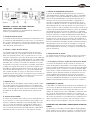
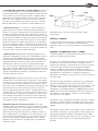
ANALOG SURROUND RECEIVER / PROCESSOR OR
TW
O-CHANNEL STEREO SYSTEM CONNECTION
Some analog A/V receivers and processors (without Dolby Digital
®
or DTS
®
capability) have a line-level subwoofer output. Others
have left- and right-channel line-level outputs, as do some stereo
receivers and integrated amplifiers. All separate stereo preamps
and surround processors have line-level outputs. If your system is
built around one of these, it will almost always be best to use the
RSA-500’s stereo line level inputs. This will allow use of the
crossover and level controls (Figure 4). You will need one or two
shielded, high quality interconnect cables of appropriate length
with RCA plugs on each end. Your dealer can help you select
suitable cables.
• Subwoofer Output – Connect the subwoofer output jack to
one or both of the line-level input jacks on the RSA-500.
• Preamp Outputs on Receiver or Integrated Amplifier – If
your receiver or integ
rated amplifier has spare preamplifier out-
puts for its front left and right channels and no subwoofer output,
connect these to the stereo line-level inputs on the RSA-500.
• Pre-out/Main-in Loops on Receiver or Integrated Amplifier
Some receivers and integrated amplifiers have their preamplifier
and power amplifier sta
ges connected externally via jumpers. If
yours has its left and right front channels connected this way, you
can connect the RSA-500 to those preamp outputs. You will need
a pair of Y-adaptors, each with two male RCA plugs and one
female RCA jack. Remove the jumpers for the two channels. For
each, plug one leg of a Y-adaptor into the preamp output jack and
another into the main amp input jack. Plug the cables leading to
the RSA-500 into the female ends of the Y-adaptors.
• Separate Preamplifier or Surround Processor – You will
need a pair of
Y-adaptors, each with one male RCA plug and two
female RCA jacks. Unplug the cables leading from the front left-
and right-channel outputs on the preamp or processor and plug
the Y-adaptors into them. For each channel, plug the cable lead-
ing to the power amplifier into one of the RCA jacks on the Y-
adaptor and the cable leading to the RSA-500 into the other.
• Crossover Adjustment – Set the control to the approximate
low-frequency limit of your main left and right front speakers.
If
you don’t have their specifications, take an educated guess
based on the size of the speakers. A large speaker will usually
work down to lower frequencies than a small speaker. So for a
large floorstanding loudspeaker, you might start with the
Crossover frequency set all the way down to 40Hz, whereas for
very small satellite speakers you might want to turn it all the way
up to 120Hz. Typical bookshelf speakers would tend to be in the
50Hz to 80Hz range. If the crossover frequency is set higher than
100Hz, the subwoofer should be in the front of the room
near the front main speakers.
• Level Control – Play a variety of music recordings containing
strong but not overpowering bass.
Adjust the RSA-500 level con-
trol until the music sounds consistently warm and natural. If you
have trouble getting enough low bass without the sound becom-
ing boomy, it probably means the Crossover control is set too
high. Try turning it down a bit at a time until the problem goes
away. If the sound is thin until you turn the subwoofer Level up so
much that lower bass is too prominent, start by changing the set-
ting of the Phase control. If that does not entirely solve the prob-
lem, you probably need to raise the Crossover frequency.
• Phase Control – In some installations the setting of the Phase
control ma
y not make much difference, whereas in others it may
be necessary to go back and forth between the Phase and Level
controls for a while in order to get the very best blend with the
main speakers. Since each control setting (including the one for
crossover frequency in the receiver or processor) affects the opti-
mum settings for the others, it often takes a while to get every-
thing dialed in just right. Start with the Phase control at 0° and
Figure 4
RSA-500 SUBWOOFER AMPLIFIER

play a recording with a prominent, repeating bass line in your lis-
tening position. Repeat this process with the control in the 180°
position. Use the setting that yields the greatest bass output.
General Comments About Adjustments: Since any change in
the setting of one control tends to change the optimum settings
f
or the others to some degree, the adjustment process is very
interactive and involves a great deal of trial and error. If after a
period of listening and calibration you are still not happy, it may
mean that you need to experiment a little with the location of the
subwoofer. That, of course, also interacts with everything else.
Again, patience is a virtue. The end result will be well worth the
effort.
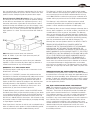
NOTE: Minimum clearence when rack mounted:
Height- 0"
Width- 3" per side Depth (from rear panel)- 6"
CARE AND CLEANING
The only thing you should ever need to do to your subwoofer
amplifier is to dust it occasionall
y. Never apply any abrasive or
solvent-based cleaner or any harsh detergent.
WARRANTY—U.S. AND CANADA ONLY
The Warranty below is valid only for sales to consumers in the
United Sta
tes or Canada.
KLIPSCH, L.L.C. ("KLIPSCH") warrants this product to be free
from defects in materials and workmanship (subject to the terms
set forth below) for a period of five (5) years from the date of
purchase. During the Warranty period, KLIPSCH will repair or
replace (at KLIPSCH’s option) this product or any defective parts
(excluding electronics and amplifiers). For products that have
electronics or amplifiers, the Warranty on those parts is for a
period of two (2) years from the date of purchase.
To obtain Warranty service, please contact the KLIPSCH author-
ized dealer from which you purchased this product. If your dealer
is not equipped to perform the repair of your KLIPSCH product, it
can be returned, freight paid, to KLIPSCH for repair. Please call
KLIPSCH at 1-800-KLIPSCH for instructions. You will need to ship
this product in either its original packaging or packaging affording
an equal degree of protection.
Proof of purchase in the form of a bill of sale or receipted invoice,
which is evidence that this product is within the Warranty period,
must be presented or included to obtain Warranty service.
This Warranty is invalid if (a) the factory-applied serial number
has been altered or removed from this product or (b) this product
was not purchased from a KLIPSCH authorized dealer. You may
call 1-800-KLIPSCH to confirm that you have an unaltered serial
number and/or you purchased from a KLIPSCH authorized dealer.
This Warranty is only valid for the original purchaser and will
automatically terminate prior to expiration (if applicable) if this
product is sold or otherwise transferred to another party.
This Warranty does not cover cosmetic damage or damage due to
misuse, abuse, negligence, acts of God, accident, commercial use
or modification of, or to any part of, the product. This Warranty
does not cover damage due to improper operation, maintenance
or installation, or attempted repair by anyone other than KLIPSCH
or a KLIPSCH dealer which is authorized to do KLIPSCH warranty
work. Any unauthorized repairs will void this Warranty. This
Warranty does not cover product sold AS IS or WITH ALL FAULTS.
REPAIRS OR REPLACEMENTS AS PROVIDED UNDER THIS
WARRANTY ARE THE EXCLUSIVE REMEDY OF THE CONSUMER.
KLIPSCH SHALL NOT BE LIABLE FOR ANY INCIDENTAL OR
CONSEQUENTIAL DAMAGES FOR BREACH OF ANY EXPRESS OR
IMPLIED WARRANTY ON THIS PRODUCT. EXCEPT TO THE EXTENT
PROHIBITED BY LAW, THIS WARRANTY IS EXCLUSIVE AND IN LIEU
OF ALL OTHER EXPRESS AND IMPLIED WARRANTIES WHATSO-
EVER, INCLUDING BUT NOT LIMITED TO, THE WARRANTY OF
MERCHANTABILITY AND FITNESS FOR A PRACTICAL PURPOSE.
Some states do not allow the exclusion or limitation of incidental
or consequential damages or implied warranties so the above
exclusions may not apply to you. This Warranty gives you specific
legal rights, and you may have other rights, which vary from state
to state.
WARRANTY OUTSIDE THE UNITED STATES AND CANADA
The Warranty on this product if it is sold to a consumer outside of
the United Sta
tes or Canada shall comply with applicable law and
shall be the sole responsibility of the distributor that supplied this
product. To obtain any applicable warranty service, please contact
the dealer from which you purchased this product, or the distribu-
tor that supplied this product.
FCC AND CANADA COMPLIANCE INFORMATION:
NOTE: This equipment has been tested and found to comply with
the limits f
or a Class B digital device, pursuant to part 15 of the
FCC Rules. These limits are designed to provide reasonable pro-
tection against harmful interference in a residential installation.
This equipment generates, uses and can radiate radio frequency
energy and, if not in-stalled and used in accordance with the
instructions, may cause harmful interference to radio communica-
tions. However, there is no guarantee that interference will not
occur in a particular installation. If this equipment does cause
harmful interference to radio or television reception, which can be
determined by turning the equipment off and on, the user is
encouraged to try to correct the interference by one or more of
the following measures:

RSA-500 SUBWOOFER AMPLIFIER
• Reorient or relocate the receiving antenna.
• Increase the separation between the equipment and receiver.
• Connect the equipment into an outlet on a circuit different from
that to which the receiver is connected.
• Consult the dealer or an experienced radio/TV technician
for help.
Approved under the verification provision of FCC Part 15 as a
Class B Digital Device.
Caution: Changes or modifications not expressly approved by
Klipsch
Audio Technologies could void the user's authority to
operate this device.
This Class B digital apparatus complies with Canadian ICES-003.
Cet appareil numérique de la classe B est conforme à la norme
NMB-003 du Canada.
Page is loading ...
Page is loading ...
Page is loading ...
Page is loading ...
Page is loading ...
Page is loading ...
Page is loading ...
Page is loading ...
Page is loading ...
Page is loading ...
-
 1
1
-
 2
2
-
 3
3
-
 4
4
-
 5
5
-
 6
6
-
 7
7
-
 8
8
-
 9
9
-
 10
10
-
 11
11
-
 12
12
-
 13
13
-
 14
14
-
 15
15
-
 16
16


Klipsch RSA-500-BL Owner's manual
- Category
- Subwoofers
- Type
- Owner's manual
- This manual is also suitable for
Ask a question and I''ll find the answer in the document
Finding information in a document is now easier with AI
in other languages
Related papers
Other documents
-
Acoustic Research HD510 User manual
-
Energy Take Classic 5.1 User manual
-
 Energy Speaker Systems ESW-V10 User manual
-
Monitor Audio Radius serie User guide
-
Focal SUB 600 P User manual
-
JBL SUB80P Wireless Powered Subwoofer Owner's manual
-
 Energy Speaker Systems S12.3 User manual
-
JBL subwoofer User manual
-
Bryston Mini-T-Sub-R1.0 Owner's manual
-

