Page is loading ...

The Chore-Time Thrust Plate Kit is used to hold the Potentiometer Gear in place, prolonging the life of the
Potentiometer Gear on the Chore-Time Linear Lift
TM
. Using this equipment for any other purpose or in a way
not within the operating recommendations specified in this manual will void the warranty and may cause
personal injury.
This manual is designed to provide comprehensive planning, installation, safety, operation, and parts listing
information.
Carefully read all safety messages in this manual and on your equipment safety signs. Follow recommended
precautions and safe operating practices. Keep safety signs in good condition. Replace missing or damaged
safety signs.
DANGER: Electrical Hazard
Disconnect electrical power before inspecting or servicing equipment Ground
all electrical equipment for safety. All electrical wiring must be done by a
qualified electrician in accordance with local and national electric codes.
Ground all non-current carrying metal parts to guard against electrical shock.
With the exception of motor overload protection, electrical disconnects and
over current protection are not supplied with the equipment.
DANGER: Rotating Parts
Severe personal injury will result, if the electrical power is not disconnected,
prior to servicing the equipment. Do Not operate with cover removed.
Potentiometer Thrust Plate Kit
(50421)
Installation & Operator’s
Instruction Manual
Thank You
The employees of Chore-Time Equipment would like
to thank you for your recent Chore-Time purchase. If
a problem should arise, your Chore-Time distributor
can supply the necessary information to help you.
General
Safety Information
Rotating Parts!
Do not operate with
covers removed!
2527-10
Disconnect electrical power
before working on system,
equipment may start auto-
matically. Otherwise severe
personal injury will result.
DANGER
MV1897AJanuary 2006

Potentiometer Thrust Plate Kit Installation Potentiometer Thrust Plate Kit (50421)
2
MV1897A
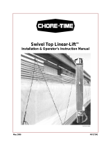
Run the Linear Lift
TM
to move the Bronze Nut all the way to the motor end, with the outer and inner shut-off Set
Collars together at the end of the operating range (See Figure 1). If the Linear Lift
TM
has been connected to an inlet
cable system, and is set to stop at the inner Set Collar somewhere else on the Switch Rod, disconnect the Linear
Lift
TM
from the inlet system cable to allow the Set Collars to be located together. This will allow the Linear Lift
TM
to
be fully synchronized with the Potentiometer Assembly. Remove the four 1/4-20 Nuts (Item 3, Figure 1), and
remove the existing Lower Cover Panel from the Linear Lift
TM
Assembly. Remove the two Self-Tapping Sheet Metal
Screws (Item 7) that hold the Potentiometer Assembly (Item 8) in place. Do not discard the Screws; they will be
used to later to install the Potentiometer with the new Thrust plate.
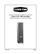
With the cord pointed down as shown below, wind the Potentiometer Assembly Gear CLOCKWISE until it stops.
Now turn the gear COUNTER-CLOCKWISE for half a turn. The Potentiometer Assembly is now reset for the full
stroke range of the Linear Lift
TM
.
Potentiometer Thrust Plate Kit Installation
3
1
2
2
5
4
Item Description
1
Linear Lift
TM
2 Lower Cover
3 Potentiometer Assembly
4 Outer Set Collar
5 Inner Set Collar
6 Bronze Nut
7 Self Tapping Sheet Metal Screws
8 Potentiometer Assembly
6
Motor End
7
8
Figure 1. Removing the Cover and Potentiometer / Collar Position
Remove old cover
CLOCKWISE
2
Item Description
1 Potentiometer Assembly
2 Potentiometer Gear
Figure 2. Setting Potentiometer
1

Potentiometer Thrust Plate Kit (50421) Potentiometer Thrust Plate Kit Installation
MV1897A
3
Insert the 1/4-20 Screw (Item 1) (incl. in parts pkg.) into the Thrust Bracket (Item 2) and attach it with the 1/4-
20 Lock Nut (Item 3) (incl. in parts pkg.) as shown. Place the Thrust Bracket down onto the Potentiometer
Assembly (Item 4), making sure that the 1/4-20 Screw is inserted into the hole in the Potentiometer Gear (Item 5).
Set the Potentiometer Assembly, with the Thrust Bracket in place, over the same holes that you removed it from
earlier (See Figure 4). Fasten the Potentiometer assembly and Thrust Bracket (Item 1) to the Base with the Sheet
Metal Screws (Item 2) that you removed earlier, but do not tighten them at this time. Slide the Potentiometer
Assembly toward the Threaded Drive Rod (Item 3) until the teeth of the Gear make full contact with the Drive
Rod threads. Tighten the Screws in the Base. Route the cord (Item 4) under the threaded Drive Rod and the Switch
Actuator Rod and on through the black fitting on the Cover Assembly (Item 5) that you removed earlier. Allow
2" to 3" of cord through the fitting for easy wire connection inside the white plastic connection box. Tighten the
black fitting to the cord and re-attach the Cover Assembly to the Linear Lift
TM
.
Item Description
1 1/4-20 Screw (Included in Parts Package)
2 Thrust Bracket
3 1/4-20 Lock Nut (Included in Parts Package)
4 Potentiometer Assembly
5 Potentiometer Gear
Figure 3. Assembling Thrust Bracket
Insert 1/4-20 Screw
into hole in Pot. Gear
2
1
4
5
2
1
3
Figure 4. Positioning and Fastening Potentiometer Assembly
1
3
4
2" to 3"
Minimum
2
5
Item Description
1 Potentiometer Assembly and Thrust Bracket
2Sheet Metal Screws (removed earlier)
3 Threaded Drive Rod
4 Cord (routed under Threaded Rod)
5 Cover Assembly

Parts List Potentiometer Thrust Plate Kit (50421)
4
MV1897A
Parts List
Item Description Part Number
1
Lower Linear Lift
TM
Cover
47835-2
2 Terminal Box 36649
3 Switch Box Cover 6776
4 Gasket 6777
5 Liquid Tight Connector 1/2" 23779
6 Potentiometer Assembly 48182
7 Potentiometer Gear (16 Pitch 36 Tooth) 41825
8 Conduit Lock Nut with Seal 39-20512
9 Potentiometer Thrust Bracket 50420
10 1/4-20 x .50 Philips Screw 4424-1
11 1/4-20 HX Lock Nut 8159
1
2
3
5
4
6
7
8
Figure 5. Parts List
9
10
11

Potentiometer Thrust Plate Kit (50421) Potentiometer Wiring and Mounting
MV1897A
5
The correct wiring of the Potentiometer leads
for the Control signal depends on the
mounting and application of the Linear-Lift
TM
.
Figure 6 shows how the unit can be used
either to close the attachment by retracting
cable into the unit or by extending cable out of
the unit. The proper lead connections are
shown in Figure 6.
Potentiometer Connection and Operation
Figure 7 shows the schematic of the Potentiometer and which color lines are associated with rotation, direction,
and position of the Bronze Nut.
Chore-Time Equipment (“Chore-Time”) warrants each new Chore-Time product manufactured by it to be free from defects
in material or workmanship for one year from and after the date of initial installation by or for the original purchaser. If such
a defect is found by the Manufacturer to exist within the one-year period, the Manufacturer will, at its option, (a) repair or
replace such product free of charge, F.O.B. the factory of manufacture, or (b) refund to the original purchaser the original
purchase price, in lieu of such repair or replacement. Labor costs associated with the replacement or repair of the product are
not covered by the Manufacturer.
Conditions and Limitations
1. The product must be installed by and operated in accordance with the instructions published by the Manufacturer or
Warranty will be void.
2. Warranty is void if all components of the system are not original equipment supplied by the Manufacturer.
3. This product must be purchased from and installed by an authorized distributor or certified representative thereof or
the Warranty will be void.
4. Malfunctions or failure resulting from misuse, abuse, negligence, alteration, accident, or lack of proper maintenance
shall not be considered defects under the Warranty.
5. This Warranty applies only to systems for the care of poultry and livestock. Other applications in industry or
commerce are not covered by this Warranty.
The Manufacturer shall not be liable for any Consequential or Special Damage which any purchaser may suffer or claim
to suffer as a result of any defect in the product. “Consequential” or “Special Damages” as used herein include, but are not
limited to, lost or damaged products or goods, costs of transportation, lost sales, lost orders, lost income, increased overhead,
labor and incidental costs and operational inefficiencies.
THIS WARRANTY CONSTITUTES THE MANUFACTURER’S ENTIRE AND SOLE WARRANTY AND THIS
MANUFACTURER EXPRESSLY DISCLAIMS ANY AND ALL OTHER WARRANTIES, INCLUDING, BUT NOT
LIMITED TO, EXPRESS AND IMPLIED WARRANTIES AS TO MERCHANTABILITY, FITNESS FOR PARTICULAR
PURPOSES SOLD AND DESCRIPTION OR QUALITY OF THE PRODUCT FURNISHED HEREUNDER.
Chore-Time Distributors are not authorized to modify or extend the terms and conditions of this Warranty in any manner or
to offer or grant any other warranties for Chore-Time products in addition to those terms expressly stated above. An officer
of CTB, Inc. must authorize any exceptions to this Warranty in writing. The Manufacturer reserves the right to change models
and specifications at any time without notice or obligation to improve previous models.
Potentiometer Wiring and Mounting
Warranty
Closing
Closing
Wire Control Signal to
White and Black Leads
W
I
N
C
H
W
I
N
C
H
Wire Control Signal to
White and Red Leads
Figure 6. Wiring of Leads
CW Rotation
Black
Red
White
(Common)
Linear Lift
Fully Retracted
Linear Lift
Fully Extended
Figure 7. Connection and Operation
1) Resistance across White & Red is maximum when
fully extended.
2) Resistance across White and Black is maximum when fully retracted.
3) Potentiometer rotation is defined as the turning direction when
viewed from the shaft side of the Potentiometer.
4) Chore-Tronics Controllers read increasing resistance=curtain closing.
5) Potentiometer is a 10-turn device that reads from 0 to 10 KOHM.
Notes:

Warranty Potentiometer Thrust Plate Kit (50421)
6
MV1897A
Note: The original, authoritative version of this manual is the [English] version produced by
CTB, Inc. or any of its subsidiaries or divisions, (hereafter collectively referred to as "CTB").
Subsequent changes to any manual made by any third party have not been reviewed nor
authenticated by CTB. Such changes may include, but are not limited to, translation into
languages other than [English], and additions to or deletions from the original content. CTB
disclaims responsibility for any and all damages, injuries, warranty claims and/or any other
claims associated with such changes, inasmuch as such changes result in content that is different
from the authoritative CTB-published [English] version of the manual. For current product
installation and operation information, please contact the customer service and/or technical
service departments of the appropriate CTB subsidiary or division. Should you observe any
questionable content in any manual, please notify CTB immediately in writing to: CTB Legal
Department, P.O. Box 2000, Milford, IN 46542-2000 USA.
Revisions to this Manual
Page No. Description of Change
New Manual
Contact your nearby Chore-Time distributor or representative for additional parts and information.
CTB Inc.
P.O. Box 2000 • Milford, Indiana 46542-2000 • U.S.A.
Phone (219) 658-4101 • Fax (877) 730-8825
E-Mail: ctb@ctbinc.com • Internet: http//www.ctbinc.com
Printed in the U.S.A.
/