Digi 24XStream Telephone Modem User manual
- Category
- Networking
- Type
- User manual
This manual is also suitable for

XStream-PKG-T™ Telephone RF Modem
XStream Telephone RF Modem
RF Module Operation
Telephone Module Operation
RF Communication Modes
Appendices
Product Manual v5.x00
XStream RF Modem Part Numbers: X09-001PK…-T… X24-009PK…-T... XH9-001PK…-T...
X09-009PK…-T… X24-019PK…-T… XH9-009PK…-T…
X09-019PK…-T… XH9-019PK…-T…
Reliable 900 MHz & 2.4 GHz Stand-alone RF Modems by MaxStream, Inc.
355 South 520 West, Suite 180
Lindon, UT 84042
Phone: (801) 765-9885
Fax: (801) 765-9895
M100111
2006.02.24
www.maxstream.net (live chat support)

XStream‐PKG‐T™TelephoneRFModem–ProductManualv5.x00[2006.02.24]
© 2006 MaxStream, Inc. All rights reserved
Nopartofthecontentsofthismanualmaybetransmittedor
reproducedinanyformorbyanymeanswithoutthewritten
permissionofMaxStream,Inc.
XStream™,XStream‐PKG‐R™andXStream‐PKG‐T™are
registeredtrademarksofMaxStream,Inc.
TechnicalSupport:
Phone:(801)765‐9885
LiveChat:
www.maxstream.net
©2006MaxStream,Inc.,ConfidentialandProprietary ii

XStream‐PKG‐T™TelephoneRFModem–ProductManualv5.x00[2006.02.24]
Contents
1. XStream Telephone RF Modem 4
1.1. Key Features 4
1.1.1. Worldwide Acceptance 4
1.2. Product Overview 5
1.2.1. Specifications 5
1.3. External Interface 6
1.3.1. Front and Back Views 6
1.4. Block Diagram 7
1.5. Pin Signals 8
1.5.1. RJ-11 Connector Pin Signals 8
1.5.2. DB-9 Connector Pin Signals 8
2. RF Module Operation 9
2.1. Modes of Operation 9
2.1.1. Idle Mode 9
2.1.2. Transmit Mode 10
2.1.3. Receive Mode 11
2.1.4. Sleep Mode 12
2.1.5. Command Mode 14
2.2. RF Module Configuration 15
2.2.1. Command Reference Table 15
2.2.2. AT Command Mode 16
2.2.3. Binary Command Mode 18
3. Telephone Module Operation 20
3.1. Telephone Module Configuration 20
3.1.1. Command Reference Tables 22
3.1.2. Telephone Module Configuration Example 25
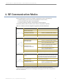
4. RF Communication Modes 26
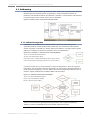
4.1. Addressing 27
4.1.1. Address Recognition 27
4.2. Basic Communications 28
4.2.1. Streaming Mode (Default) 28
4.2.2. Repeater Mode 29
4.3. Acknowledged Communications 32
4.3.1. Acknowledged Mode 32
4.3.2. Multi-Streaming Mode 34
Appendix A: Agency Certifications 38
FCC Certification 38
OEM Labeling Requirements 39
Antenna Usage 40
FCC-Approved Antennas 41
IC (Industry Canada) Certification 42
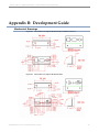
Appendix B: Development Guide 43
Mechanical Drawings 43
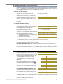
RF Module Configuration 44
X-CTU Software 44
RF Module Commands (Long Descriptions) 45
Appendix C: Additional Information 61
1-Year Warranty 61
Ordering Information 61
Contact MaxStream 62
©2006MaxStream,Inc.,ConfidentialandProprietary iii

XStream‐PKG‐T™TelephoneRFModem–ProductManualv5.x00[2006.02.24]
1. XStreamTelephoneRFModem
The XStream-PKG-T RF Modem provides long range data communications and advanced
networking for the expanding RFd2d (Radio Frequency Device-to-Device) segment of the wireless
market. Out-of-box, the modem comes configured to sustain long
range wireless communications between devices.
The modem transfers a standard asynchronous serial data stream
between two or more modems. Its built-in telephone interfacing
allows for rapid integration into existing data systems.
1.1. Key Features
Long Range at a Low Cost
Easy-to-Use
Out-of-Box RF Experience
(no configuration required)
No Master/Slave setup dependencies
External DIP Switch configurations
Advanced configurations using simple
AT & binary commands
7-28 VDC power supply
Transparent Operation
Portable
(small form factor & low power)
Software-selectable interfacing rates
Support for multiple data formats
XII™ Interference Immunity
I/O line passing RF communication
options available
Unlimited Technical Support
is included
9XStream-PKG-T (900 MHz) Range:
• Indoor/Urban: up to 1500’ (450 m)
• Outdoor line-of-sight: up to 7 miles
(11 km) w/ 2.1 dBm dipole antenna
• Outdoor line-of-sight: up to 20 miles
(32 km) w/ high gain antenna
24XStream-PKG-T (2.4 GHz) Range:
• Indoor/Urban: up to 600’ (180 m)
• Outdoor line-of-sight: up to 3 miles
(5 km) w/ 2.1 dBm dipole antenna
• Outdoor line-of-sight: up to 10 miles
(16 km) w/ high gain antenna
Receiver sensitivity: -110 dBm (@ 900 MHz),
–105 dBm (@ 2.4 GHz)
Advanced Networking & Security
True Peer-to-Peer (no “master” required), Point-
to-Point, Point-to-Multipoint & Multidrop
Retries and Acknowledgements
FHSS (Frequency Hopping Spread Spectrum)
7 hopping channels, each with over 65,000
unique network addresses available
1.1.1. Worldwide Acceptance
FCC Certified (USA) Refer to Appendix A for FCC Requirements.
Devices that contain XStream RF Modems inherit MaxStream’s FCC Certification
ISM (Industrial, Scientific & Medical) frequency band
Manufactured under ISO 9001:2000 registered standards
9XStream-PKG-T (900 MHz) RF Modems approved for use in US, Canada,
Australia, Israel (and more).
©2006MaxStream,Inc.,ConfidentialandProprietary 4

XStream‐PKG‐T™TelephoneRFModem–ProductManualv5.x00[2006.02.24]
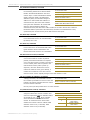
1.2. Product Overview
When networked with other MaxStream Radio Modems (RS-232/485, Ethernet, USB, etc.), the
XStream PKG Telephone Modem provides a transparent wireless link between serial devices and
telephone modems. The telephone interface extends MaxStream’s over-the-air range with the
reach of any PSTN (Public Switched Telephone Network).
Figure1‐01. On‐boardTelephone&RFModulesInsidetheXStream‐PKG‐TTelephoneRFModem
The XStream-PKG-T RF Modem comes configured to provide an immediate wireless link between
devices; however, both the on-board RF and Telephone Modules can be configured for additional
functionality through the use of a simple AT command interface [Refer to the RF Module
Configuration [p
15] & Telephone Module Configuration [p20] sections for programming options].
1.2.1. Specifications
Table1‐01. Specificationsof theXStream‐PKG‐TTelephoneRFModem
Specification 9XStream-PKG-T (900 MHz) 24XStream-PKG-T (2.4 GHz)
Performance
Indoor/Urban Range Up to 1500’ (450 m) Up to 600’ (180 m)
Outdoor
RF line-of-sight Range
Up to 7 miles (11 km) w/ dipole antenna
Up to 20 miles (32 km) w/ high-gain antenna
Up to 3 miles (5 km) w/ dipole antenna
Up to 10 miles (16 km) w/ high-gain antenna
Interface Data Rate 1200 - 57600 bps (software selectable) 1200 - 57600 bps (software selectable)
Throughput Data Rate 9,600 bps 19,200 bps 9,600 bps 19,200 bps
RF Data Rate 10,000 bps 20,000 bps 10,000 bps 20,000 bps
Transmit Power Output 100 mW (20 dBm) 100 mW (20 dBm) 50 mW (17 dBm) 50 mW (17 dBm)
Receiver Sensitivity -110 dBm -107 dBm -105 dBm -102 dBm
Power Requirements
Supply Voltage 7-28 VDC (optional jumpers allow the PKG-T to be powered with a 5V supply)
Receive (RX) Current 140 mA 160 mA
Transmit (TX) Current 220 mA 230 mA
General
Frequency 902-928 MHz 2.4000-2.4835 GHz
Spread Spectrum Frequency Hopping, Wide band FM modulator
Network Topology Peer-to-Peer, Point-to-multipoint, Point-to-Point, Multidrop
Channel Capacity 7 hop sequences share 25 frequencies
Physical Properties
Enclosure Extruded aluminum, black anodized
Enclosure Size 2.750” x 6.500” x 1.124” (7.90 cm x 16.51 cm x 3.80 cm)
Operating Temperature 0 to 70º C (commercial), -40 to 85º C (industrial)
Antenna
Type ½ wave dipole whip, 6.75” (17.1 cm), 2.1 dBi Gain
Connector Reverse-polarity SMA (RPSMA)
Impedance 50 ohms unbalanced
Certifications
FCC Part 15.247 OUR9XSTREAM OUR-24XSTREAM
Industry Canada (IC) 4214A-9XSTREAM 4214A 12008
©2006MaxStream,Inc.,ConfidentialandProprietary 5

XStream‐PKG‐T™TelephoneRFModem–ProductManualv5.x00[2006.02.24]
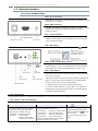
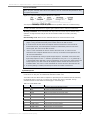
1.3. External Interface
1.3.1. Front and Back Views
1-02a. RJ-11 Connector
Figure1‐02. FrontView
Standard RJ-11 connector is used to connect to telephone lines. [Pin
descriptions are on page 8]
1-02b. DB-9 Serial Port
Standard female DB-9 (RS-232) DCE connector is primarily used as
a medium to configure RF module and Telephone module
parameter values.
1-02c. Power Connector
7-28 VDC Power, Center positive, 5.5/2.1 mm Connector –
Installing internal jumpers J1 & J5 allows the unit to be powered
with a regulated 5V supply.
1‐02b.DB‐9SerialPort
1‐02a.RJ‐11Connector 1‐02c.Power
1-03a. DIP Switch
DIP Switch provides external control of speaker and
functions.
Figure1‐03. BackView
1-03b. Config (Configuration) Switch
Configuration Switch provides an alternate way to enter AT
Command Mode. To enter AT Command Mode at the RF Modem’s
default baud rate, read the Reset Switch entry [Figure 1-03c].
1‐03g.
LED
1‐03d.
Antenna
Port
©2006MaxStream,Inc.,ConfidentialandProprietary 6
1-03c. Reset Switch
1‐03c.
ResetSwitch
1‐03f.
RSSILEDs
Reset Switch forces both the Telephone Module and the RF Module
into reset (or re-boot).
1‐03e.
I/O&PowerLEDs
1‐03b.
ConfigSwitch
This switch can also be used in conjunction with the Config Switch
[Figure 1-03b] to enter the RF Module into AT Command Mode.
To enter the RF module into AT Command Mode:
(i.) Simultaneously press the Reset and Config switches,
(ii.) release the Reset Switch, (iii.) then after 1 sec. release the
Config Switch. The RF modem then enters AT Command Mode at
the module’s default baud rate.
1‐03a.DIPSwitch
1-03d. Antenna Port
50Ω RF signal connector for connecting to external antenna - Antenna connector type is RPSMA (Reverse Polarity SMA).
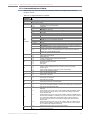
1-03e, 1-03f, & 1-03g. LED Indicators
Table1‐02. LEDindicatorsandtheirmeanings
1-03e. I/O & Power LEDs 1-03f. RSSI LEDs 1-03g. (Data Carrier Detect) LED
LED indicators visualize diagnostic status information.
The RF Modem’s status is represented as follows:
Yellow (top LED) = Serial Data Out (to host)
Green (middle) = Serial Data In (from host)
Red (bottom) = Power/TX Indicator
(Red light is on when powered,
off briefly during RF transmission)
Used to determine RSSI (Received Signal Strength Indicator)
and fade margin available in the wireless link:
3 Green LEDs ON = Very Strong (> 30 dB fade margin)
2 Green LEDs ON = Strong (> 20 dB fade margin)
1 Green LED ON = Moderate (> 10 dB fade margin)
0 Green LED ON = Weak (< 10 dB fade margin)
Fade Margin = The difference between the incoming signal
strength and the modem’s receiver sensitivity.
Illuminated yellow LED indicates telephone
connection is established and
(Data Carrier
Detect) is asserted.
This signal is controlled by the Telephone
Module.

XStream‐PKG‐T™TelephoneRFModem–ProductManualv5.x00[2006.02.24]
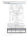
1.4. Block Diagram
Figure1‐04. PKG‐TRFModemInternalBlockDiagram
(Low‐assertedsignalsdistinguishedbyhorizontallineoverpinname.)
The PKG-T RF Modem provides a wireless link between devices out-of-box and without
configuration. If more advanced features are needed, the XStream RF Module and Telephone
Module can be configured via the DB-9 connector or a wireless link.
The Data Path Switch is controlled by the
and lines of the DB-9 connector. In the PKG-
T’s RF Modem’s default state (when nothing is attached to the DB-9 connector), data is routed
between the RF module and the telephone module. In this case, the Telephone Module
communicates directly with a remote RF Modem and receives commands through a wireless link.
Table1‐03. DataPathSwitchSettings‐SignalRoutingbetweenRS‐232DB‐9connector,RFModule&
TelephoneModule(Low‐assertedsignalsdistinguishedbyhorizontallineoverpinname.)
Result
+10V +10V DB-9 connects to RF Module for configuration.
+10V -10V DB-9 connects to Telephone Module for configuration.
-10V (default state) -10V / +10V (default state)
RF Module and Telephone Module are connected to each other and not
to the DB-9 connector.
This is the default state of the RF Modem
(when DB-9 is not connected).
Refer to the RF Module Configuration [p15] and Telephone Module Configuration [p20] sections
for more information about configurations of the on-board Telephone and RF Modules.
©2006MaxStream,Inc.,ConfidentialandProprietary 7

XStream‐PKG‐T™TelephoneRFModem–ProductManualv5.x00[2006.02.24]
1.5. Pin Signals
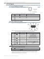
1.5.1. RJ-11 Connector Pin Signals
Figure1‐05. TipandRingPinsoftheRJ‐11Connector
Table1‐04. RJ‐11SignalsandtheirimplementationsontheXStream‐PKG‐TRFModem
Pin Pin Name Description Implementation
3 T1 Tip Dial-tone and talk circuit
4 R1 Ring Dial-tone and talk circuit
2, 5 not used
1, 6 not connected
1.5.2. DB-9 Connector Pin Signals
Figure1‐06. PinsoftheFemaleDB‐9(RS‐232)Connector
Table1‐05. DB‐9(RS‐232)SignalsandtheirimplementationsontheXStream‐PKG‐TRFModem
(Low‐assertedsignalsaredistinguishedbyhorizontallineoverpinname.)
Pin Pin Name Description Implementation
1 Data-Carrier-Detect Set to +5V
2 RXD Received Data
Serial Data OUT of the RF Modem
(to host, from over-the-air))
3 TXD Transmitted Data
Serial Data IN to the RF Modem
(from host, to be transmitted over-the-air)
4 Data-Terminal-Ready
Enables configuration (Serial Port Method) of XStream
OEM RF Module or Telephone Module
5 GND Ground Ground
6 Data-Set-Ready Set to +5V
7 Request-to-Send
Connects DB-9 data lines to XStream RF Module
or Telephone Module when
asserted (+10V)
8 Clear-to-Send Set to +5V
9 RI Ring Indicator not used
Jumpers
Table1‐06. JumpersontheXIB‐TInterfaceBoard
Jumper Description
J3 Connects either or of the Telephone Modem to DI3 (SLEEP) of the on-board RF Module.
Non-populated J1 and J5 jumpers are also available for bypassing the high input voltage
regulators. This would allow the RF modem to be powered with a 5 volt supply. Contact
MaxStream Technical Support for more information.
©2006MaxStream,Inc.,ConfidentialandProprietary 8

XStream‐PKG‐T™TelephoneRFModem–ProductManualv5.x00[2006.02.24]
2. RFModuleOperation
2.1. Modes of Operation
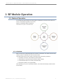
An on-board RF module enables the XStream-PKG-T RF Modem to send and receive data over-
the-air. The RF module operates in five modes.
Figure2‐01. RFModule’sModesofOperation
Themodemcanonlybeinonemodeatatime.
2.1.1. Idle Mode
When not receiving or transmitting data, the module is in Idle Mode. The module uses the same
amount of power in Idle Mode as it does in Receive Mode.
The modem shifts into the other modes of operation under the following conditions:
• Serial data is received in the DI Buffer (Transmit Mode)
• Valid RF data is received through the antenna (Receive Mode)
• Command Mode Sequence is issued (Command Mode)
• Sleep Mode condition is met (Sleep Mode)
After responding to any of the preceding conditions, the modem automatically transitions back
into Idle Mode.
©2006MaxStream,Inc.,ConfidentialandProprietary 9

XStream‐PKG‐T™TelephoneRFModem–ProductManualv5.x00[2006.02.24]
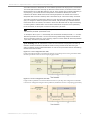
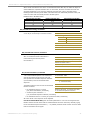
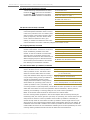
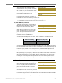
2.1.2. Transmit Mode
When the first byte of serial data is received from the UART in the DI buffer, the modem
attempts to shift to Transmit Mode and initiate an RF connection with other modems.
Figure2‐02. TransmissionofDat
nsmit
a
Once in Tra Mode, the
nnel.
s
s,
on,
buffer.
p to 64
e
modem initializes a
communications cha
Channel initialization is the
process of sending an RF
initializer that synchronize
receiving modems with the
transmitting modem. When
streaming multiple RF packet
the RF Initializer is only sent in
front of the first packet.
During channel initializati
incoming serial data
accumulates in the DI
After the channel is initialized,
data in the DI buffer is
grouped into packets (u
bytes in each packet) and is transmitted. The modem continues to transmit data packets until th
DI buffer is empty. Once transmission is finished, the modem returns to Idle Mode. This
progression is shown above.
As the transmitting modem nears the end of the transmission, it inspects the DI buffer to see if
more data exists to be transmitted. This could be the case if more bytes arrived from the host
after the transmission began. If more data is pending, the transmitting modem assembles a
subsequent packet for transmission.
RF Packet
The RF packet is the sequence of data used for communicating information between MaxStream
Modems. An RF Packet consists of an RF Initializer and RF Data.
©2006MaxStream,Inc.,ConfidentialandProprietary 10
Figure2‐03. RFPacketComponents
*WhenstreamingmultipleRFpackets,theRFInitializerisonlysentinfrontofthefirstpacket.
RF Initializer
An RF initializer is sent each time a new connection sequence begins. The RF initializer contains
channel information that notifies receiving modems of information such as the hopping pattern
used by the transmitting modem. The first transmission always sends an RF initializer.
An RF initializer can be of various lengths depending on the amount of time determined to be
required to prepare a receiving modem. For example, a wake-up initializer is a type of RF
initializer used to wake remote modems from Sleep Mode (Refer to the FH, LH, HT and SM
Commands for more information). The length of the wake-up initializer should be longer than the
length of time remote modems are in cyclic sleep.

XStream‐PKG‐T™TelephoneRFModem–ProductManualv5.x00[2006.02.24]
Header
The header contains network addressing information that is used to filter incoming RF data. The
receiving modem checks for matching a VID, Hopping Channel and Destination Address. Data
that does not pass through all three network filter layers is discarded.
Figure2‐04. FiltrationLayersContainedintheHeader
CRC (Cyclic Redundancy Check)
To verify data integrity and provide built-in error checking, a 16-bit CRC (Cyclic Redundancy
Check) is computed for the transmitted data and attached to the end of each RF packet. On the
receiving end, the receiving modem computes the CRC on all incoming RF data. Received data
that has an invalid CRC is discarded [Refer to Receive Mode section].
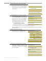
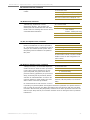
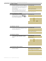
2.1.3. Receive Mode
If a modem detects RF data while operating in Idle Mode, the modem transitions into Receive
Mode to start receiving RF packets.
Figure2‐05. ReceptionofRFDataÆ
After a packet is received, the
modem checks the CRC (cyclic
redundancy check) to ensure that
the data was transmitted without
error. If the CRC data bits on the
incoming packet are invalid, the
packet is discarded. If the CRC is
valid, the packet proceeds to the
DO Buffer.
The modem returns to Idle Mode
after valid RF data is no longer
detected or after an error is
detected in the received RF data.
If serial data is stored in the DI
buffer while the modem is in
Receive Mode, the serial data will
be transmitted after the modem
is finished receiving data and
returns to Idle Mode.
©2006MaxStream,Inc.,ConfidentialandProprietary 11

XStream‐PKG‐T™TelephoneRFModem–ProductManualv5.x00[2006.02.24]
2.1.4. Sleep Mode
Sleep Modes are not supported by the XStream-PKG-T Telephone RF Modem; however, Sleep
Modes can be implemented on remote modems connected to the telephone RF modem host.
Sleep Modes enable the XStream Modem to operate at minimal power consumption when not in
use. Three Sleep Mode options are available:
• Pin Sleep (Host Controlled)
• Serial Port Sleep (Wake on Serial Port activity)
• Cyclic Sleep (Wake on RF activity)
For the modem to transition into Sleep Mode, the modem must have a non-zero SM (Sleep Mode)
Parameter and one of the following must occur:
1. The modem is idle (no data transmission or reception) for a user-defined period of time
[Refer to ST (Time before Sleep) Command].
2. SLEEP pin is asserted (only for Pin Sleep option).
In Sleep Mode, the modem will not transmit or receive data until the modem first transitions to
Idle Mode. All Sleep Modes are enabled and disabled using SM Command. Transitions into and
out of Sleep Modes are triggered by various mechanisms as shown in the table below.
For more information about Sleep Modes, refer to the individual commands listed in “Related
Commands” column of the table. SM Command is the best starting point for implementing sleep
mode configurations.
Pin Sleep (SM = 1)
Pin Sleep requires the least amount of power. In order to achieve this state, Pin 2 (SLEEP) must
be asserted (high). The module remains in Pin Sleep until the Sleep pin is de-asserted.
After enabling Pin Sleep, DI3 controls whether the XStream Module is active or in Sleep Mode.
When DI3 is de-asserted (low), the module is fully operational. When DI3 is asserted (high), the
module transitions to Sleep Mode and remains in its lowest power-consuming state until the
Sleep pin is de-asserted. DI3 is only active if the module is setup to operate in this mode;
otherwise the pin is ignored.
Once in Pin Sleep Mode, DO2 (pin 1,
) is de-asserted (high), indicating that data should not
be sent to the module. Pin 8 (PWR) is also de-asserted (low) when the module is in Pin Sleep
Mode.
Note: The module will complete a transmission or reception before activating Pin Sleep.
Serial Port Sleep (SM = 2)
Serial Port Sleep is a Sleep Mode in which the XStream Module runs in a low power state until
serial data is detected on the DI pin.
When Serial Port Sleep is enabled, the module goes into Sleep Mode after a user-defined period
of inactivity (no transmitting or receiving of data). This period of time is determined by ST (Time
before Sleep) Command. Once a character is received through the DI pin, the module returns to
Idle Mode and is fully operational.
Cyclic Sleep (SM = 3-8)
Cyclic Sleep is the Sleep Mode in which the XStream Module enters into a low-power state and
awakens periodically to determine if any transmissions are being sent.
When Cyclic Sleep settings are enabled, the XStream Module goes into Sleep Mode after a user-
defined period of inactivity (no transmission or reception on the RF channel). The user-defined
period is determined by ST (Time before Sleep) Command.
While the module is in Cyclic Sleep Mode, DO2 (
) is de-asserted (high) to indicate that data
should not be sent to the module during this time. When the module awakens to listen for data,
DO2 is asserted and any data received on the DI Pin is transmitted. PWR is also de-asserted
(low) when the module is in Cyclic Sleep Mode.
©2006MaxStream,Inc.,ConfidentialandProprietary 12

XStream‐PKG‐T™TelephoneRFModem–ProductManualv5.x00[2006.02.24]
The module remains in Sleep Mode for a user-defined period of time ranging from 0.5 seconds to
16 seconds (SM Parameters 3 through 8). After this interval of time, the module returns to Idle
Mode and listens for a valid data packet for 100 ms. If the module does not detect valid data (on
any frequency), the module returns to Sleep Mode. If valid data is detected, the module
transitions into Receive Mode and receives incoming RF packets. The module then returns to
Sleep Mode after a Period of inactivity that is determined by ST “Time before Sleep” Command.
The module can also be configured to wake from cyclic sleep when DI3 (SLEEP) is de-asserted
(low). To configure a module to operate in this manner, PW (Pin Wake-up) Command must be
issued. Once DI3 is de-asserted, the module is forced into Idle Mode and can begin transmitting
or receiving data. It remains active until no data is detected for the period of time specified by
the ST Command, at which point it resumes its low-power cyclic state.
Note: The cyclic interval time defined by SM (Sleep Mode) Command must be shorter than the interval
time defined by LH (Wake-up Initializer Timer).
For example: If SM=4 (Cyclic 1.0 second sleep), the LH Parameter should equal 0x0B (“1.1” seconds).
With these parameters set, there is no risk of the receiving module being asleep for the duration of
wake-up initializer transmission. “Cyclic Scanning” explains in further detail the relationship between
“Cyclic Sleep” and “Wake-up Initializer Timer”
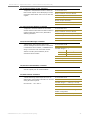
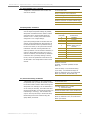
Cyclic Scanning. Each RF transmission consists of an RF Initializer and payload. The wake-up
initializer contains initialization information and all receiving modules must wake during the
wake-up initializer portion of data transmission in order to be synchronized with the transmitting
module and receive the data.
Figure2‐06. CorrectConfiguration(LH>SM):
Lengthofthewake‐upinitializerexceedsthetimeintervalofCyclicSleep.Thereceiverisguaranteedtodetect
thewake‐upinitializerandreceivetheaccompanyingpayloaddata.
Figure2‐07. IncorrectConfiguration(LH<SM):
Lengthofwake‐upinitializerisshorterthanthetimeintervalofCyclicSleep.Thisconfigurationisvulnerable
tothereceiverwakingandmissingthewake‐upinitializer(andthereforealsotheaccompanyingpayloaddata).
©2006MaxStream,Inc.,ConfidentialandProprietary 13

XStream‐PKG‐T™TelephoneRFModem–ProductManualv5.x00[2006.02.24]
©2006MaxStream,Inc.,ConfidentialandProprietary 14
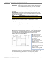
2.1.5. Command Mode
To modify or read RF module parameters, the module must first enter into Command Mode - the
state in which incoming characters are interpreted as commands. Two command types are
available for programming the on-board RF module:
• AT Commands
• Binary Commands
Refer to the RF Module Configuration sections [beginning on the next page] for more information.
For information about programming the on-board telephone module, refer to the Telephone
Module Configuration [p
20] section.
NOTE: The XStream-PKG-T RF Modem automatically powers up to a Command Mode for the on-
board telephone module, the on-board RF Module does not. To enter RF Module into Command
Mode for the purpose of programming the module, follow the refer to the RF Module Configuration
section [next page].

XStream‐PKG‐T™TelephoneRFModem–ProductManualv5.x00[2006.02.24]
©2006MaxStream,Inc.,ConfidentialandProprietary 15
2.2. RF Module Configuration
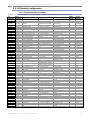
2.2.1. Command Reference Table
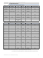
Table2‐01. CommandsUniquetotheon‐boardRFModule(Fordetailedcommanddescriptions,refertoAppendixB)
AT
Command
Binary
Command
AT Command Name Range Command Category
# Bytes
Returned
Factory
Default
AM v4.30* 0x3A (58d) Auto-set MY - Networking & Security - -
AT 0x05 (5d) Guard Time After 0x02 – 0xFFFF [x 100 msec] Command Mode Options 2 0x0A (10d)
BD v4.2B* 0x15 (21d) Baud Rate
Standard baud rates: 0 – 6
(custom rates also supported)
Serial Interfacing 2
factory-set
RF data rate
BK v4.30* 0x2E (46d) Serial Break Passing 0 – 1 Serial Interfacing 1 0
BO v4.30* 0x30 (48d) Serial Break Timeout 0 - 0xFFFF [x 1 second] Serial Interfacing 2 0
BT 0x04 (4d) Guard Time Before 0 – 0xFFFF [x 100 msec] Command Mode Options 2 0x0A (10d)
CB v4.30* 0x33 (51d) Connection Duration Timeout 0x01 – 0xFFFF [x 100 msec] Networking & Security 2 0x28 (4d sec)
CC 0x13 (19d) Command Sequence Character 0x20 – 0x7F Command Mode Options 1 0x2B (“+”)
CD v4.2B* 0x28 (40d) DO3 Configuration 0 – 4 Serial Interfacing 1 0
CE v4.30* 0x34 (52d) Connection Inactivity Timeout 0 – 0xFFFF [x 10 msec] Networking & Security 2 0x64 (1d sec)
CF v4.30* 0x35 (53d) Connection Failure Count 0 – 0xFFFF Networking & Security 2 0
CL v4.30* 0x39 (57d) Last Connection Address [read-only] Diagnostics 2 -
CM v4.30* 0x38 (56d) Connection Message 0 – 1 Networking & Security 1 0
CN 0x09 (9d) Exit AT Command Mode - Command Mode Options - -
CO v4.30* 0x2F (47d) DO3 Timeout 0 - 0xFFFF [x 1 second] Serial Interfacing 2 0x03
CS v4.27D* 0x1F (31d) DO2 Configuration 0 – 4 Serial Interfacing 1 0
CT 0x06 (6d) Command Mode Timeout 0x02 – 0xFFFF [x 100 msec] Command Mode Options 2 0xC8 (200d)
DC v4.30* 0x37 (55d) Disconnect - Networking & Security - -
DR v4.30* 0x2D (45d) DI3 Configuration 0 – 4 Serial Interfacing 1 0
DT 0x00 (0d) Destination Address 0 – 0xFFFF Networking & Security 2 0
E0 0x0A (10d) Echo Off - Command Mode Options - -
E1 0x0B (11d) Echo On - Command Mode Options - -
ER 0x0F (15d) Receive Error Count 0 – 0xFFFF Diagnostics 2 0
FH 0x0D (13d) Force Wake-up Initializer - Sleep (Low Power) - -
FL 0x07 (7d) Software Flow Control 0 – 1 Serial Interfacing 1 0
FT v4.27B* 0x24 (36d) Flow Control Threshold 0 – 0xFF [bytes] Serial Interfacing 2 varies
GD 0x10 (16d) Receive Good Count 0 – 0xFFFF Diagnostics 2 0
HP 0x11 (17d) Hopping Channel 0 – 6 Networking & Security 1 0
HT 0x03 (3d) Time before Wake-up Initializer 0 – 0xFFFF [x 100 msec] Sleep (Low Power) 2 0xFFFF
ID v4.2B* 0x27 (39d) Modem VID
User-settable: 0x10 - 0x7FFF
Read-only: 0x8000 – 0xFFFF
Networking & Security 2 -
IU v4.30* 0x3B (59d) DI2, DI3 Update Timer 0 - 0xFFFF [x 100 msec] Serial Interfacing 2 0x0A (10d)
LH 0x0C (12d) Wake-up Initializer Timer 0 – 0xFF [x 100 msec] Sleep (Low Power) 1 0x01
MD v4.30* 0x32 (50d) RF Mode 0 – 4 Networking & Security 1 0
MK 0x12 (18d) Address Mask 0 – 0xFFFF Networking & Security 2 0xFFFF
MY v4.30* 0x2A (42d) Source Address 0 – 0xFFFF Networking & Security 2 0xFFFF
NB v4.30* 0x23 (35d) Parity 0 – 5 Serial Interfacing 1 0
PC v4.22* 0x1E (30d) Power-up Mode 0 – 1 Command Mode Options 1 0
PK v4.30* 0x29 (41d) RF Packet Size 0 - 0x100 [bytes] Serial Interfacing 2 0x40 (64d)
PW v4.22* 0x1D (29d) Pin Wake-up 0 – 1 Sleep (Low Power) 1 0
RB v4.30* 0x20 (32d) Packetization Threshold 0 - 0x100 [bytes] Serial Interfacing 2 0x01
RE 0x0E (14d) Restore Defaults - (Special) - -
RN v4.22* 0x19 (25d) Delay Slots 0 – 0xFF [slots] Networking & Security 1 0
RO v4.2A* 0x21 (33d) Packetization Timeout 0 – 0xFFFF [x 200 µsec] Serial Interfacing 2 0
RP v4.2A* 0x22 (34d) RSSI PWM Timer 0 - 0x7F [x 100 msec] Diagnostics 1 0
RR v4.22* 0x18 (24d) Retries 0 – 0xFF Networking & Security 1 0
RS v4.22* 0x1C (28d) RSSI 0x06 – 0x36 [read-only] Diagnostics 1 -
RT 0x16 (22d) DI2 Configuration 0 - 2 Serial Interfacing 1 0
RZ v4.30* 0x2C (44d) DI Buffer Size [read-only] Diagnostics - -
SB v4.2B* 0x36 (54d) Stop Bits 0 - 1 Serial Interfacing 1 0
SH v4.27C* 0x25 (37d) Serial Number High 0 – 0xFFFF [read-only] Diagnostics 2 -
SL v4.27C* 0x26 (38d) Serial Number Low 0 – 0xFFFF [read-only] Diagnostics 2 -
SM 0x01 (1d) Sleep Mode 0 – 8 Sleep (Low Power) 1 0
ST 0x02 (2d) Time before Sleep 0x10 – 0xFFFF [x 100 msec] Sleep (Low Power) 2 0x64 (100d)
SY 0x17 (23d) Time before Initialization 0 – 0xFF [x 100 msec] Networking & Security 1 0 (disabled)
TO v4.30* 0x31 (49d) DO2 Timeout 0 - 0xFFFF (x 1 sec) Serial Interfacing 2 0x03
TR v4.22* 0x1B (27d) Transmit Error Count 0 – 0xFFFF Diagnostics 2 0
TT v4.22* 0x1A (26d) Streaming Limit 0 – 0xFFFF [0 = disabled] Networking & Security 2 0xFFFF
VR 0x14 (20d) Firmware Version 0 x 0xFFFF [read-only] Diagnostics 2 -
WR 0x08 (8d) Write - (Special) - -
*FirmwareVersioninwhichthecommandwasfirstintroduced.Allsubsequentversionsalsosupportthecommand.

XStream‐PKG‐T™TelephoneRFModem–ProductManualv5.x00[2006.02.24]
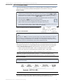
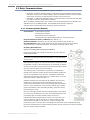
2.2.2. AT Command Mode
This section illustrates how to configure the on-board RF Module using standard AT Commands.
Refer to p
17 for programming examples that implement the instructions on this page.
Hardware Setup:
The on-board RF Module is configured through the DB-9 connector of the PKG-T RF Modem. To
configure the on-board RF Module, DIP Switch 2 must be ON (up) and both and
must be asserted (+10V RS-232 logic). Most serial communications software (including
MaxStream’s X-CTU Software) will assert and when the serial com port is opened.
1. Attach an RS-232 cable to the DB-9 connectors of the XStream-PKG-T RF Modem and a PC.
2. Move DIP Switch 2 ( Control) to the ON (up) position.
3. Launch MaxStream’s X-CTU™ Software and select the “PC Settings” Tab.
[Refer to the X-CTU section of Appendix B for information about X-CTU.]
In the ‘Com Port Setup’ section, match the Baud, Parity and Stop Bit settings of the PC com
port with those of the RF Module. [Refer to BD & NB commands.]
Figure2‐08. HardwareSetupforConfiguringtheRFModule
Enter AT Command Mode:
Enter the AT Command Mode Sequence using the “Terminal” tab* of the X-CTU Software.
[OR]
Assert (low) the pin and turn the power going to the modem off and back on. This can
be achieved by (i.) simultaneously pressing the Reset and Config switches [Figures 1-03b & 1-
03c], (ii.) releasing the Reset Switch, (iii.) then after 1 sec. releasing the Config Switch. The RF
Module then enters AT Command Mode at the module’s default baud rate.
* The “Modem Configuration” tab can also be used to send AT commands to the RF module.
When using this tab, make sure the settings under the ‘AT Command Setup’ sub-section of the
“PC Settings” tab match the AT Command Mode Sequence parameters stored in the RF Module.
The AT Command Mode Sequence (default parameter values are shown in parenthesis):
• Observe Guard Time Before (ATBT = 0x0A, no characters sent for one second)
• Enter three copies of the Command Sequence Character (ATCC = 0x2D, ASCII “---“)
• Observe Guard Time After (ATAT = 0x0A, no characters sent for one second)
IMPORTANT: The default Command Sequence Character (“-“) is unique to the XStream-PKG-T
Telephone RF Modem. All other MaxStream Radio Modems use the “+” character as their default.
Send AT Commands:
When using the “Terminal” tab of the X-CTU Software, send AT Commands and parameters using
the syntax shown below:
Table2‐02. SyntaxforsendingRFModuleATCommands:
To read a parameter value stored in a register, leave the parameter field blank.
The preceding example would change destination address of the RF Module to “1F”. To store the
new value to non-volatile (long-term) memory, the WR (Write) Command must follow.
©2006MaxStream,Inc.,ConfidentialandProprietary 16

XStream‐PKG‐T™TelephoneRFModem–ProductManualv5.x00[2006.02.24]
©2006MaxStream,Inc.,ConfidentialandProprietary 17
System Response. When a command is sent to the module, the module parses and executes
the command. Upon successful execution of a command, the module returns an “OK” message. If
execution of command results in an error, the module returns an “ERROR” message.
Multiple AT Commands. Multiple AT commands can be entered on one line with one carriage
return at the end of the line. Each command must be delimited by a comma (spaces in between
are optional). The “AT” prefix is only sent before the first command and should not be included
with subsequent commands in a line.
Exit AT Command Mode:
Send the ATCN (Exit Command Mode) Command.
[OR]
If no valid AT Commands are received within the time specified by CT (Command Mode Timeout)
Command, the RF Module automatically returns to Idle Mode.
AT Command Examples
EXAMPLE #1: Modify DT (Destination Address) parameter using the Terminal tab
The following steps show how to read & modify the destination address of a PKG-T RF modem.
1. Follow the “Hardware Setup” steps outlined on p14; then open the X-CTU program
(Start --> Programs --> MaxStream --> X-CTU).
2. Under the ‘Com Port Setup’ section of the “PC Settings” tab, select the Com Port that will be
used to connect the RF module; then select the ‘Baud’ setting that matches the module’s
baud rate. Use RF Module default values for all other fields.
3. Select the “Terminal” tab; then send the following AT commands:
Method 1 (One line per command)
Issue AT Command System Response
--- OK<CR> (Enters RF module into AT Command Mode)
ATDT <Enter> (reads & displays current destination address)<CR>
ATDT1A0D<Enter> OK<CR> (Changes DT address to 0x1A0d)
ATWR <Enter> OK<CR> (Writes new value to non-volatile memory)
ATCN <Enter> OK<CR> (Exits RF Module from AT Command Mode)
Method 2 (Multiple commands on one line)
Issue AT Command System Response
--- OK<CR> (Enters into AT Command Mode)
ATDT <Enter> (reads & displays current destination address)<CR>
ATDT1A0D, WR, CN <Enter> OK<CR> (Send multiple AT Commands)
EXAMPLE #2: Restore Defaults using the Modem Configuration tab
The following steps show how to read currently stored RF module parameter values; then restore
the RF module parameters to their factory-default states.
1. Follow the “Hardware Setup” steps outlined on p14; then open the X-CTU program
(Start --> Programs --> MaxStream --> X-CTU).
2. Under the ‘Com Port Setup’ section of the “PC Settings” tab, select the Com Port that will be
used to connect the RF module; then select the ‘Baud’ setting that matches the module’s
baud rate. Use RF Module default values for all other fields.
3. Under the ‘Host Setup’ sub-tab, enter “-“ in the ASCII text box to match the RF module’s
CC (Command Sequence Character) parameter.
4. Select the “Modem Configuration” tab; then select the Read’ button to read currently stored
parameter values of the RF module.
5. Select the ‘Load’ button, then navigate to and open the appropriate profile. Profiles carry a
“.pro” file extension and are located in the ‘Profiles’ folder of the MaxStream CD.
6. Select the ‘Write’ button to save RF module default values to non-volatile memory.

XStream‐PKG‐T™TelephoneRFModem–ProductManualv5.x00[2006.02.24]
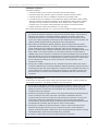
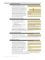
2.2.3. Binary Command Mode
Sending and receiving parameter values using binary commands is the fastest way to change
operating parameters of the XStream RF Modem. Binary commands are used most often to
sample signal strength (RS parameter) and/or error counts; or change modem addresses and
channels for polling data systems. Since the sending and receiving of register values takes place
through the same serial data path as 'live' data (received RF payload), interference between the
two types of data can be a concern.
Common questions about using binary commands:
• What are the implications of asserting CMD while live data is being sent or received?
• After sending serial data, is there a minimum time delay before CMD can be asserted?
• Is a delay required after CMD is de-asserted before payload data can be sent?
• How does one discern between live data and data received in response to a command?
The CMD pin must be asserted in order to send binary commands to the RF modem. The CMD pin
can be asserted to recognize binary commands anytime during the transmission or reception of
data. The status of the CMD signal is only checked at the end of the stop bit as the byte is shifted
into the serial port. The application does not allow control over when data is received, except by
waiting for dead time between bursts of communication.
If the command is sent in the middle of a stream of payload data to be transmitted, the
command will essentially be executed in the order it is received. If the radio is continuously
receiving data, the radio will wait for a break in the received data before executing the command.
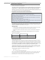
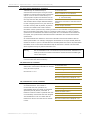
The
signal will frame the response coming from the binary command request [refer to Figure
below].
A minimum time delay of 100 µs (after the stop bit of the command byte has been sent) must be
observed before the CMD pin can be de-asserted. The command executes after all parameters
associated with the command have been sent. If all parameters are not received within 0.5
seconds, the modem returns to Idle Mode.
Note: When parameters are sent, they are two bytes long with the least significant byte sent first.
Binary commands that return one parameter byte must be written with two parameter bytes.
Commands can be queried for their current value by sending the command logically ORed (bit-
wise) with the value 0x80 (hexadecimal) with CMD asserted. When the binary value is sent (with
no parameters), the current value of the command parameter is sent back through the DO pin.
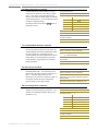
Figure2‐09. BinaryCommandWritethenRead
Signal#4isCMD
Signal#1istheDINsignaltotheradio
Signal#2istheDOUTsignalfromtheradio
Signal#3is
Inthisgraph,avaluewaswrittentoaregisterand
thenreadouttoverifyit.Whilenotinthemiddle
ofotherreceiveddata,notethatthe
signal
outlinesthedataresponseoutofthemodem
IMPORTANT: For the RF Module to recognize a binary command, the RT (DI2 Configuration)
parameter must be set to one. If binary programming is not enabled (RT ≠ 1), the
RF module will not recognize that the CMD pin is asserted and therefore will not
recognize the data as binary commands.
©2006MaxStream,Inc.,ConfidentialandProprietary 18

XStream‐PKG‐T™TelephoneRFModem–ProductManualv5.x00[2006.02.24]
Binary Command Example
The following example steps through an RF module configuration process using binary
commands.
To Send Binary Commands:
Example: Use binary commands to change the RF Module’s destination address to 0x1A0D and
save the new address to non-volatile memory.
1. RT Command must be set to “1” in AT Command Mode to enable binary programming.
2. Assert CMD (Pin is driven high). (Enter Binary Command Mode)
3. Send Bytes [Parameter bytes must be 2 bytes long]:
00 (Send DT (Destination Address) Command)
0D (Least significant byte of parameter bytes)
1A (Most significant byte of parameter bytes)
08 (Send WR (Write) Command)
4. De-assert CMD (Pin is driven low). (Exit Binary Command Mode)
Note: is high when command is being executed. Hardware flow control must be disabled as
will hold off parameter bytes.
©2006MaxStream,Inc.,ConfidentialandProprietary 19

XStream‐PKG‐T™TelephoneRFModem–ProductManualv5.x00[2006.02.24]
3. TelephoneModuleOperation
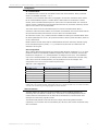
3.1. Telephone Module Configuration
The Telephone Module features a rich set of AT commands that allow flexibility in operations. On
power-up or reset, the Telephone Module operates in command mode and will accept AT
commands either from an RS-232 serial cable or from another MaxStream RF Modem (PKG-R,
PKG-U, etc.) over a wireless link.
Refer to the Telephone Module Configuration Example section [p
25] for programming examples.
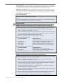
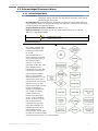
Hardware Setup Option 1 – Serial Port Method:
Configurations made through the serial line [Figure 3-01]
©2006MaxStream,Inc.,ConfidentialandProprietary 20
1. Connect an RS-232 cable to the DB-9 connector of the PKG-T RF Modem.
2. Move DIP Switch 1 (Speaker Control) to the ON (up) position and DIP Switch 2
( control) to the OFF (down) position. This will configure the Data Path
Switch to connect the DB-9 and Telephone Module.
3. Assert (+10V). Most serial communications software (including MaxStream’s X-CTU
Software) will assert when the serial com port is opened.
Figure3‐01. HardwareSetup‐SerialPortMethod
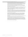
Hardware Setup Option 2 – Wireless Link Method
Configurations made via a remote PKG RF Modem [Figure 3-02]
1. Detach cable from the DB-9 connector (Absence of the cable will automatically de-assert
(-10V RS-232 level)).
2. Connect wirelessly to the RF Modem (AT Commands are sent from a PC to a device such as
the PKG-R RS-232/485 RF Modem via a serial port. The PKG-R Modem then relays
commands over-the-air to the PKG-T Telephone RF Modem.)
Figure3‐02. HardwareSetup‐WirelessLinkMethod
Page is loading ...
Page is loading ...
Page is loading ...
Page is loading ...
Page is loading ...
Page is loading ...
Page is loading ...
Page is loading ...
Page is loading ...
Page is loading ...
Page is loading ...
Page is loading ...
Page is loading ...
Page is loading ...
Page is loading ...
Page is loading ...
Page is loading ...
Page is loading ...
Page is loading ...
Page is loading ...
Page is loading ...
Page is loading ...
Page is loading ...
Page is loading ...
Page is loading ...
Page is loading ...
Page is loading ...
Page is loading ...
Page is loading ...
Page is loading ...
Page is loading ...
Page is loading ...
Page is loading ...
Page is loading ...
Page is loading ...
Page is loading ...
Page is loading ...
Page is loading ...
Page is loading ...
Page is loading ...
Page is loading ...
Page is loading ...
-
 1
1
-
 2
2
-
 3
3
-
 4
4
-
 5
5
-
 6
6
-
 7
7
-
 8
8
-
 9
9
-
 10
10
-
 11
11
-
 12
12
-
 13
13
-
 14
14
-
 15
15
-
 16
16
-
 17
17
-
 18
18
-
 19
19
-
 20
20
-
 21
21
-
 22
22
-
 23
23
-
 24
24
-
 25
25
-
 26
26
-
 27
27
-
 28
28
-
 29
29
-
 30
30
-
 31
31
-
 32
32
-
 33
33
-
 34
34
-
 35
35
-
 36
36
-
 37
37
-
 38
38
-
 39
39
-
 40
40
-
 41
41
-
 42
42
-
 43
43
-
 44
44
-
 45
45
-
 46
46
-
 47
47
-
 48
48
-
 49
49
-
 50
50
-
 51
51
-
 52
52
-
 53
53
-
 54
54
-
 55
55
-
 56
56
-
 57
57
-
 58
58
-
 59
59
-
 60
60
-
 61
61
-
 62
62


Digi 24XStream Telephone Modem User manual
- Category
- Networking
- Type
- User manual
- This manual is also suitable for
Ask a question and I''ll find the answer in the document
Finding information in a document is now easier with AI
Related papers
Other documents
-
 CallingSYS ZZQ8 User manual
-
 Data Connect DSP19.2 User manual
-
Sunricher SR-3001DIN User manual
-
FSR K-10D Owner's manual
-
DAVIS 7625 Owner's manual
-
B&B Electronics 9XTend-PKG-E User manual
-
 Xpress XEB09-C User manual
-
 Xpress Network Router XEB09-C User manual
-
Dwyer Wireless Temperature/Humidity User manual
-
 GAPOSA RIP868 Quick start guide


