Page is loading ...

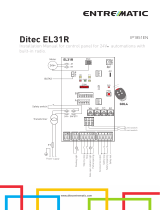
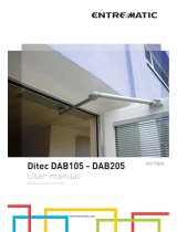
Ditec LOGICM
IP1854EN
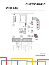
Control panel installation manual for 230 V~ automation with one or two motors.
www.ditecentrematic.com
TM
RF
AUX
AUX
JR6
POWER
SA
IN
11
12
F1
F2
TC RP TR R1
OM
J7
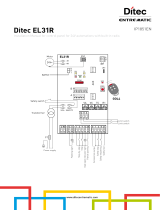
15 14 13 12 11 00112345678920 41UWVXZYLN
LN
com
com
Electric lock
Power suuply
Flashing light
Lamp
Limit switch
Limit switch
Accessories output
Automatic closing
Opening
Closing
Step by step
Opening safety device
Closing safety device
Safety reopening
Stop
Partial opening
Safety test
M1
1~
M2
1~
D5 S5 JT
NIO
SO
JR10
JR4
EO
1
ON
23456
1
4
2
F
U
S
E
F
U
S
E
LOGICM

2
IP1854EN - 2013-03-01

3
IP1854EN - 2013-03-01
Index
Subject Page
1. General safety precautions 4
2. EC declaration of conformity 4
3. Technical data 4
3.1 Applications
4
4. Commands 5
4.1
Self-controlled safety edge
5
5. Outputs and accessories 6
6. Adjustments 7
6.1 Trimmer
7
6.2 Dip-switch
7
6.3 Jumper
8
6.4 Signals
8
7. Start-up 9
8. Troubleshooting 10
9. Example application for two-motors swing gates 11
10. Example application for one-motor swing gate 12
11. Example application for sliding gate 13
12. Example application for barrier 13
13. Example of parallel 14
Caption
i
STOP
This symbol indicates informations which are useful for correct product function.
This symbol indicates instructions or notes intended for technical and expert personnel.
This symbol indicates options and parameters which are only available with the indicated item.
This symbol indicates operations not to be effected for not compromise the correct operation of the automation.
This symbol indicates options and parameters which are not available with the indicated item.
This symbol indicates instructions or notes regarding safety issues which require particular attention.

4
IP1854EN - 2013-03-01
1. General safety precautions
This installation manual is intended for qualified personnel only.
Installation, electrical connections and adjustments must be performed in accordance with Good Working Methods and in
compliance with applicable regulations.
Before installing the product, carefully read the instructions. Bad installation could be hazardous.
The packaging materials (plastic, polystyrene, etc.) should not be discarded in the environment or left within reach of children,
as these are a potential source of hazard.
Before installing the product, make sure it is in perfect condition.
Do not install the product in an explosive environment and atmosphere: gas or inflammable fumes are a serious hazard risk.
Before installing the motors, make all structural changes relating to safety clearances and protection or segregation of all areas
where there is risk of being crushed, cut or dragged, and danger areas in general.
Make sure the existing structure is up to standard in terms of strength and stability. The motor manufacturer is not responsible
for failure to use Good Working Methods in building the frames to be motorized or for any deformation occurring during use.
The safety devices (photocells, safety edges, emergency stops, etc.) must be installed taking into account: applicable laws and
directives, Good Working Methods, installation premises, system operating logic and the forces developed by the motorized door.
The safety devices must protect any areas where the risk exists of being crushed, cut or gragged, or where there are any other
risks generated by the motorized door.
Apply hazard area notices required by applicable regulations.
Each installation must clearly show the identification details of the motorized door.
When necessary, connect the motorized door to a reliable earth system made in accordance with applicable safety regulations.
During installation, maintenance and repair, interrupt the power supply before opening the lid to access the electrical parts.
The protective casing of the automation must be removed by qualified personnel only.
To handle electronic parts, wear earthed antistatic conductive bracelets. The motor manufacturer declines all responsibility
in the event of component parts being fitted that are not compatible with the safe an correct operation.
For repairs or replacements of products only original spare parts must be used. The installer shall provide all information relating
to automatic, manual and emergency operation of the motorized door, and provide the user with operating instructions.
The manufacturer Entrematic Group AB with headquarters in Lodjursgatan 10, SE-261 44 Landskrona, Sweden
declares that the control panel Ditec LOGICM is in conformity with the provisions of the following EC directives:
EMC Directive 2004/108/CE;
Low Voltage Directive 2006/95/CE.
Landskrona, 29-01-2013 Marco Pietro Zini
(President & CEO)
2. EC Declaration of conformity
3. Technical data
LOGICM LOGICMJ
Power supply 230 V~ 50/60 Hz 120 V~ 60 Hz
F1 fuse F6,3A F6,3A
F2 fuse F3,15A F3,15A
One motor output 230 V~ 5A max 120 V~ 6,3A max
Two motor output
230 V~
2x2,5A max
120 V~
2x3,15A max
Accessories power supply 24 V
0,5 A 24 V 0,5 A
Temperature min -20 °C max +55 °C min -20 °C max +55 °C
Degree of protection IP55 IP55
Dimensions 187X261X105 187X261X105
i
3.1 Applications
NOTE: the given operating and performance features can only be guaranteed with the use of DITEC accessories and
safety devices.

5
IP1854EN - 2013-03-01
4. Commands
Command Function Description
1
2 N.O. AUTOMATIC CLOSING Permanently closing the contact enables automatic closing.
1
3 N.O. OPENING The opening operation starts when the contact is closed.
1
4 N.O. CLOSING The closing operation starts when the contact is closed.
1
5 N.O. STEP-BY-STEP With D5=ON closing the contact starts a sequential opening or closing operation: open-stop-
close-open.
With D5=OFF closing the contact starts a sequential opening or closing operation: open-stop-
close-stop-open.
Note: if automatic closing is enabled, with S5=ON the stop is not permanent but at a time that
is set by the TC, with S5=OFF the stop is permanent.
41
6
N.C. OPENING SAFETY
DEVICE
Opening the safety contact stops the current opening operation in progress and impedes any
future opening operations.
41
7
N.C. CLOSING SAFETY
DEVICE
Opening the safety contact stops the current closing operation in progress and impedes any
future closing operations.
41
6
7
N.C. SAFETY STOP Opening the safety contact stops and prevents any movement.
Note: it does not carry out the disengagement operation. Use with photocells installed only.
41
8 N.C. REVERSAL SAFETY
DEVICE
Opening the safety contact triggers a reversal of motion (re-opening) during a closing opera-
tion.
1
9 N.C. STOP Opening the safety contact stops the current operation.
EMERGENCY STOP To enable the emergency stop function (e.g. with a specific red button), connect the opening
and closing controls to terminal 9 instead of 1 (9-3, 9-4, 9-20).
1
9 N.O. HOLD-TO-RUN
FUNCTION
Permanently opening the safety contact enables the operator presence dependent function.
In this state, the opening (1-3, 1-20) and closing (1-4) controls function only if held in the pres-
sed position and the automation stops when the controls are released.
All safety switches, the step-by-step control and the automatic closing function are disabled.
1
20 PARTIAL OPENING Closing the contact activates a partial opening operation of the door wing powered by motor 1,
of the duration set with the RP trimmer.
Once the automation stops, the partial opening control performs the opposite operation to the
one performed before stoppage.
0
11
N.C. M2 LIMIT SWITCH With TC=MAX, the limit switch contact opening stops closing movement of motor 2 (M2).
With OM=OFF (1 motor mode) and DIP2=OFF, the limit switch stops closing movement of motor
1 (M1).
With OM=OFF (1 motor mode) and DIP2=ON, the limit switch stops opening movement of motor
1 (M1).
0
11 N.O. M2 PROXIMITY
LIMIT SWITCH
See Chapters 9-10, example 4.
0
12 N.C. M1 LIMIT SWITCH With TC=MAX, the limit switch contact opening stops closing movement of motor 1 (M1).
With OM=OFF (1 motor mode) and DIP2=OFF, the limit switch stops opening movement of
motor 1 (M1).
With OM=OFF (1 motor mode) and DIP2=ON, the limit switch stops closing movement of motor
1 (M1).
0
12 N.O. M1 PROXIMITY
LIMIT SWITCH
See Chapters 9-10, example 4.
WARNING: Make a jumper on all N.C. contacts if not in use. The terminals with the same number are equal.
4.1 Self-controlled safety edge SOFA1-SOFA2 or GOPAVRS
Command Function Description
GOPAV
SOFA1-SOFA2
SAFETY TEST Place the SOFA1-SOFA2 or GOPAVRS device into its housing for plug-in cards AUX.
Connecting terminal 41 enables a safety edge test cycle before every operation.
If the test fails the SA led flashes and the test is repeated.
1
6 N.C. OPENING SAFETY
DEVICE
Connect the output contact of device SOFA1-SOFA2 to terminals 1-6 on the control panel (in
series with the photocell output contact, if installed).
1
7 N.C. CLOSING SAFETY
DEVICE
Connect the output contact of device SOFA1-SOFA2 to terminals 1-7 on the control panel (in
series with the photocell output contact, if installed).
1
8 N.C. REVERSAL SAFETY
DEVICE
Connect the output contact of device SOFA1-SOFA2 to terminals 1-8 on the control panel (in
series with the photocell output contact, if installed).
ATTENTION: for quick operation on the safety edge, connect it to contact 1-6 or to contact 1-7.

6
IP1854EN - 2013-03-01
5. Output and accessories
Output Value - Accessories Description
4901 23
+-
24 V 0,5 A
Accessories power supply.
Power supply output for external accessories, including automation status lamp.
NOTE: the maximum absorption of 0.5 A corresponds to the sum of all terminals 1.
AUX
SOFA1-SOFA2
GOPAV
The control panel has two spaces for coupling board, type radio receivers, magnetic loops etc.
The coupling board working mode is selected by DIP1.
WARNING: the plug-in cards must be inserted and removed with the power supply disconnected.
11 ...
1
24 V 3 W
Automation open lamp.
Only with limit switch 0-11 (NC) connected and in one motor mode (jumper OM=OFF) will the lamp
extinguish when automation is closed.
12 ...
1
24 V 3 W
Automation closed lamp.
Only with limit switch 0-12 (NC) connected and in one motor mode (jumper OM=OFF) will the lamp
extinguish when automation is open.
13 ...
1
24 V 3 W
Automation open lamp.
A lamp lights up that extinguishes only when automation is closed.
14 ...
0
LAMPH
24 V 50 W
Flashing light.
Activated during opening and closing operations.
15 ...
0
24 V 1,2 A
24 V electric block.
Activated upon every opening command.
24 V electric motor brake.
With JR6=OFF, OM=OFF and DIP5=ON, the output is active for the entire duration of the opening
or closing motion.
24 V electric lock. With EO=OFF the output is on and the automation is closed.
15 ...
0
12 V~ 15 W
12 V electric lock.
Connect the supplied 8.2 Ω / 5 W resistance in series. Activated upon every opening command
M1
UVW
230 V~ 2,5 A
120 V (LOGICMJ)
Motor 1 (M1).
Terminal W must be connected to the common motor phase connection. The condenser must be
connected between the U and V phases.
Note: if the direction of rotation of the motor is incorrect for the desired direction of movement,
swap the U and V phases.
M2
XYZ
230 V~ 2,5 A
120 V (LOGICMJ)
Motor 2 (M2).
Terminal Z must be connected to the common motor phase connection. The condenser must be
connected between the X and Y phases.
Note: if the direction of rotation of the motor is incorrect for the desired direction of movement,
swap the X and Y phases.
NL
W... ...
LAMP
230 V~ 100 W
120 V~ (LOGICMJ)
Flashing light.
Activated during opening and closing operations.
NL
X... ...
230 V~ 100 W
120 V~ (LOGICMJ)
Courtesy light.
In one motor mode only (jumper OM=OFF and no motor connected to terminals X-Z-Y), a courtesy
light may be connected, which activates for 180 s each time a total or partial opening command
or closing command is received.

7
IP1854EN - 2013-03-01
Output Value - Accessories Description
J7
Membrane push-button panel (PT3).
Starts the opening operation.
Note: to activate the closing operation, connect the connector of the push-button panel to J7
(rotated by 180°).
Membrane push-button panel (PT3).
Causes the blocking of the movement.
Membrane push-button panel (PT3).
Starts the closing operation.
Note: to activate the opening operation, connect the connector of the push-button panel to J7
(rotated by 180°).
6. Adjustments
6.1 Trimmer
6.2 Dip-switch
Trimmer Description
TM
MIN=10 s MAX=120 s
60 s
Setting the operating time. From 10 to 120 s.
NOTE: with NC limit switch, set TM=MAX.
TR
MIN=0 s
10 s
20 s
30 s
3 s
Setting motor 1 (M1) closing delay time.
When closing, motor 1 (M1) starts after a delay set with TR from 0 to 30 s relative to M2. When opening, motor 2
(M2) starts after a delay of 3 s relative to M1.
If TR=MIN, the door wings start simultaneously.
NOTE: we recommend setting TR=MIN with non-overlapping door wings, and setting TR>3 s with overlapping door
wings.
TC
MIN=0 s MAX=120 s
Setting automatic closing time. From 0 to 120 s.
With DIP3=OFF, once a safety switch has been activated, the counter starts as soon as the safety switch is released
(for example, after passing through the photocells), and lasts for a period of time set with TC (50%).
With DIP3=ON, the counter starts when automation is opened and lasts for the entire duration set with TC (100%).
NOTE: after the activation of the stop command, once contact 1-9 has closed again, automatic closing is only ena-
bled after a total, partial or step-by-step opening command.
RF
1
5
4
3
2
Power setting.
Sets voltage supplied to motor (1=MIN / 5=MAX).
R1
MAX=disabled
MIN
Setting obstacle thrust.
The control panel is equipped with a safety system that stops motion if an obstacle is encountered during an opening
operation and either stops or reverses motion during a closing operation.
R1=MIN gives maximum obstacle sensitivity (minimum thrust).
R1=MAX disables detection (maximum thrust).
RP
0 s
30 s
Setting motor 1 (M1) partial aperture.
From 0 to 30 s.
DIP Description OFF
ON
DIP1 Radio mode. Step-by-Step. Opening.
DIP2 Direction selection with OM=OFF (one mo-
tor mode).
Opens towards right. Opens towards left.
DIP3 Restore automatic closing time. 50% 100%
DIP4 Automation status at power on.
Indicates how the control panel considers
automation when powered up.
Open.
NOTE: with a limit switch installed, prefera-
bly set DIP4=OFF.
Closed.
NOTE: if the automatic closing function is
not used, preferably set DIP4=ON.
DIP5 Electric lock release. Disabled. Enabled.
DIP6 Preflashing set at 3 s. Disabled during opening.
Enabled only with automatic closing and
with TC setting greater than 3 s.
Enabled for both opening and closing.

8
IP1854EN - 2013-03-01
6.3 Jumper
6.4 Signals
Jumper Description OFF ON
JR4 Overtravel reduction.
Reduces the overtravel distance for the
door wing.
Disabled.
NOTE: set JR4=OFF is the motor is equip-
ped with an electric brake.
Enabled.
NOTE: preferably set JR4=ON if the door
wing performs an excessive overtravel.
JR6 Application type. Sliding gate. Other applications.
NIO Electronic antifreeze system. Maintains
motor function even at low ambient tem-
peratures.
NOTE: for correct operation, the control
panel must be exposed to the same am-
bient temperature as the motors.
Enabled.
ATTENTION: do not use with LOGICMJ.
Disabled.
JR10 Maximum power at start. Disabled.
The motor starts with the voltage set with RF.
Enabled.
The motor starts at maximum power for 1 s.
OM Automation type. One motor automation (M1 only). Automation with two independent motors.
D5 Step-by-step sequence. Open-stop-close-stop-open. Open-stop-close-open.
S5 Step-by-step sequence stop duration. Permanent.
(Automatic closing disabled).
Temporary.
(Automatic closing enabled).
JT Closing operation time. Set with TM+4 s.
NOTE: set JT=OFF with hydraulic or friction
gearmotor.
Automatic.
EO Electric lock function. Powered with automation closed. Powered for 1 s at the beginning of the
opening operation.
SO Reversal safety switch func-tion. With automation stopped and contact 41-8
open, opening operations are permitted.
With automation stopped and 41-8 open, all
operations are disabled.
LED On Flashing
POWER
24 V power supply /
SA
Indicates that at least one of the safety contacts is open. Safety test failure (terminal 41).
Operations count performed (only when control panel is switched
on):
= 1000 operations
= 10000 operations
IN
Activated at every command and adjustment to the dip-switch
and jumper.
/
11
Indicates that the 0-11 limit switch contact is open.
/
12
Indicates that the 0-12 limit switch contact is open.
/

9
IP1854EN - 2013-03-01
7. Starting
• Bridge the NC safety contacts with a jumper.
• Before starting up, check the application type selected. In the case of single door wing automation, set OM=OFF. For sliding
gate automation, set JR6=OFF.
• Any limit switches installed must be adjusted so that they are triggered near the mechanical opening and closing end stops.
Set TM=MAX.
NOTE: limit switches must be kept pressed until the operation has been completed.
• If no limit switches are installed, bridge terminals 0-11 and 0-12 with jumpers and set TM to half.
• Set RF=3 and R1 to half.
• Set TR>3 s in the case of automation with two overlapping door wings.
• Switch on power.
• Swap the motor polarity if the direction of motion of the door wings is incorrect.
NOTE: the first closing operation requested after a power outage is performed, if TR>MIN, with one door wing at a time (first the
door wing powered by motor M2, then the door wing powered by motor M1), whereas if TR=MIN, the door wings start simultaneously.
• Perform opening and closing commands and check that the automation functions correctly and that the limit switches (if
installed) are correctly set.
• Connect the safety devices (removing the relative jumpers) and check that they function correctly.
• If required, activate automatic closing and adjust with the TC trimmer.
• Set RF to a position that allows the automation to function correctly while ensuring the safety of the user in the event of col-
lision.
• Set obstacle thrust with R1.
NOTE: if the door wing closing second encounters an obstacle, both door wings are reopened. The subsequent closing operation
is performed one door wing at a time.
• Ensure that the forces exerted by the door wings are compliant with EN12453-EN12445 regulations.
• If required, set the partial aperture of motor 1 with RP.
• If required, connect the radio receiver to the relative AUX connector, programme the transmitters as described in the relative
manual and check that all elements function correctly.
• Connect any other accessories and check operation.
• Once the start up and check procedures are completed, close the container.
ATTENTION: The following operations are performed with no safety devices
WARNING: the plug-in cards must be inserted and removed with the power supply disconnected.
i
NOTE: in the event of servicing or if the control panel is to be replaced, repeat the start-up procedure.

10
IP1854EN - 2013-03-01
8. Troubleshooting
Problem Possible causes Remedy
Automation does not open or close. No power.
(POWER led off).
Check that the control panel is powered cor-
rectly.
Short circuited accessories.
(POWER led off).
Disconnect all accessories from terminals 0-1
(voltage must be 24 V=) and reconnect one at
a time.
Blown line fuse.
(POWER led off).
Replace fuse.
Safety contacts are open.
(SA led on).
Check that the safety contacts are closed cor-
rectly (N.C.).
Safety contacts not correctly connected or
self-controlled safety edge SOFA1-SOFA2 not
functioning correctly.
(SA led flashing).
Check connections to terminals 6-7-8 on control
panel and connections to the self-controlled
safety edge SOFA1-SOFA2.
Release microswitch open (if installed). Check that the hatch is closed correctly and the
microswitch makes contact.
The motor thermal overload switch is open. Check for continuity between the phases of the
motors disconnected from the control panel.
Automation opens but does not close. Safety contacts are open.
(SA led on).
Check that the safety contacts are closed cor-
rectly (N.C.).
Safety contacts not correctly connected or
self-controlled safety edge SOFA1-SOFA2 not
functioning correctly.
(SA led flashing).
Check connections to terminals 6-7-8 on control
panel and connections to the self-controlled
safety edge SOFA1-SOFA2.
Photocells activated.
(SA led on).
Check that the photocells are clean and opera-
ting correctly.
The automatic closing does not work. Check that contact 1-2 is closed.
External safety devices not activating. Incorrect connections between the photocells
and the control panel.
Connect NC safety devices together in series
and remove any bridges on the control panel
terminal board.

11
IP1854EN - 2013-03-01
9. Example application for two-motors swing gates
When the LOGICM control panel is used in automation applications with two swinging door wings, one of the
following operating modes may be selected.
Example 1 - Door wings stop against mechanical end stops and in
the event of obstacle detection.
Set an operating time of 2-3 s longer than the effective time taken by
the door wing (TM<MAX) and bridge terminals 0-11-12 with jumpers.
In this configuration, each door wing will come to a stop against me-
chanical opening and closing end stops and in the event of obstacle
detection.
Example 2 - Door wings stop against limit switches and in the event
of obstacle detection.
The NC contacts of the opening and closing limit switches are con-
nected in series with the motor phases.
Set an operating time TM<MAX and bridge terminals 0-11-12 with
jumpers.
In this configuration, each door wing will come to a stop against the
opening and closing limit switches and in the event of obstacle de-
tection.
Example 3 - Door wings stop against limit switches and reverse
motion in the event of obstacle detection.
Set an operating time TM=MAX and connect the closing limit
switch NC contacts to terminals 0-11-12 and the opening limit
switch NC contacts in series with the open phase of each motor.
With this configuration, each of the door wings stops when the limit
switches are activated.
In the event of obstacle detection while opening, only the door wing
that detects the obstacle stops, performing a disengagement ope-
ration, whereas during a closing operation, both door wings reopen.
Example 4 - Door wings stop against mechanical end stops and re-
verse motion in the event of obstacle detection.
Set an operating time 2-3 s greater than the effective time taken
by the door wing (TM<MAX) and connect the closing proximity limit
switch NO contacts to terminals 0-11-12, positioning the switches
2-3 s ahead of the mechanical end stop. In this configuration, each
door wings stops against its respective mechanical closing and ope-
ning end stop. In the event of obstacle detection while opening, only
the door wing that detects the obstacle stops, performing a disenga-
gement operation. In the event of obstacle detection during closing
and before the activation of the proximity limit switch, the door wings
reopen; after the activation of the proximity limit switch, the door
wings stop against the obstacle.
Example 5 - The door wings stop against the limit switches when
opening and against the mechanical end stops when closing, and
reverse motion when an obstacle is detected.
Set an operating time 2-3 s greater than the effective time taken
by the door wing (TM<MAX) and connect the closing proximity limit
switches to terminals 0-11-12, positioning the switches 2-3 s ahead
of the mechanical end stop. Connect the opening NC limit switches
in series to the open phase of each motor. In this configuration, the
door wing stops against the mechanical end stop when closing, and
when the relative limit switch is activated when opening. When an
obstacle is detected during opening, the door wing stops, performing
a disengagement operation. In the event of obstacle detection during
closing and before the activation of the proximity limit switch, the
door wings reopen; after the activation of the proximity limit switch,
the door wings stop against the obstacle.
TM
<MAX <MAX
TC RP TR R1
15 14 13 12 11 00112345678920 41UWVXZY
com
com
M1
1~
M2
1~
Limit switch (230 V 5A)
TM TC RP TR R1
15 14 13 12 11 0011234567892041
Closing
proximity switch
<MAX <MAX
TM
<MAX <MAX
TC RP TR R1
15 14 13 12 11 00112345678920 41
TM TC RP TR R1
15 14 13 12 11 00112345678920 41UWVXZY
com
com
M1
1~
M2
1~
Opening limit switch (230 V~ 5A)
Closing
proximity switch
<MAX <MAX
TM TC RP TR R1
15 14 13 12 11 0 0112345678920 41UWVXZY
com
com
M1
1~
M2
1~
Opening limit switch (230 V 5A)
Closing
limit switch
=MAX <MAX

12
IP1854EN - 2013-03-01
10. Example application for one-motor swing gate
When the LOGICM control panel is used in automation applications with one swinging door wing, one of the
following operating modes may be selected.
Example 1 - Door wing stops against mechanical end stops and in
the event of obstacle detection.
Set an operating time of 2-3 s longer than the effective time taken by
the door wing (TM<MAX) and bridge terminals 0-11-12 with jumpers.
In this configuration, the door wing will come to a stop against me-
chanical opening and closing end stops and in the event of obstacle
detection.
Example 2 - Door wing stops against limit switches and in the event
of obstacle detection.
The NC contacts of the opening and closing limit switches are con-
nected in series with the motor phases.
Set an operation time TM<MAX and bridge terminals 0-11-12 with
jumpers.
In this configuration, the door wing stops against the opening and
closing limit switches and in the event of obstacle detection.
Example 3 - Door wing stops against limit switches and reverses
motion in the event of obstacle detection.
Set an operating time TM=MAX and connect the opening and closing
limit switch NC contacts to terminals 0-11-12.
In this configuration, the door wing stops when the limit switches
are activated.
In the event of obstacle detection while opening, the door wing stops,
performing a disengagement operation, whereas during a closing
operation, the door wing reopens.
Example 4 - Door wing stops against mechanical end stops and re-
verses motion in the event of obstacle detection.
Set an operating time of 2-3 s longer than the effective time taken by
the door wing (TM<MAX) and position the proximity limit switches 2-3
s ahead of the mechanical end stop.
In this configuration, the door wing stops against its respective me-
chanical closing and opening end stop.
In the event of obstacle detection before the activation of the proximi-
ty limit switch while opening, the door wing stops, performing a di-
sengagement operation; after the proximity limit switch is activated,
the door wing stops against the obstacle.
In the event of obstacle detection during closing and before the acti-
vation of the proximity limit switch, the door wing reopens; after the
proximity limit switch is activated, the door wing stops against the
obstacle.
Example 5 - The door wing stops against the limit switch when ope-
ning and against the mechanical end stop when closing, and rever-
ses motion in the event of obstacle detection.
Set an operating time of 2-3 s longer than the effective time taken
by the door wing (TM<MAX), position the proximity limit switches 2-3
s ahead of the mechanical end stop and connect the opening limit
switch NC in series to the opening phase of the motor.
In this configuration, the door wing stops against the mechanical
end stop when closing, and when the relative limit switch is acti-
vated when opening. When an obstacle is detected during opening,
the door wing stops, performing a disengagement operation. In the
event of obstacle detection during closing and before the activation of
the proximity limit switch, the door wing reopens; after the proximity
limit switch is activated, the door wing stops against the obstacle.
TM TC RP TR R1
OM=OFF
15 14 13 12 11 00112345678920 41
<MAX <MAX
TM TC RP TR R1
15 14 13 12 11 00112345678920 41UWVXZY
com
M1
1~
Limit switch (230 V 5A)
OM=OFF
<MAX <MAX
TM TC RP TR R1
15 14 13 12 11 00112345678920 41
Closing limit switch
Opening limit switch
OM=OFF
=MAX <MAX
TM TC RP TR R1
15 14 13 12 11 0011234567892041
Closing proximity switch
Opening proximity switch
OM=OFF
<MAX <MAX
TM TC RP TR R1
15 14 13 12 11 00112345678920 41UWVXZY
com
M1
1~
Opening limit switch (230 V 5A)
Closing
proximity switch
OM=OFF
<MAX <MAX

13
IP1854EN - 2013-03-01
11. Example application for sliding gate
12. Example application for barriers
When using the LOGICM control panel for sliding automation appli-
cations:
- set OM=OFF
- set JR6=OFF
- set TM=MAX
Connect the opening and closing limit switch NC contacts to terminals
0-11-12.
With this configuration, the door wing stops when the limit switches
are activated.
In the event of obstacle detection while opening, the door wing stops,
performing a disengagement operation, whereas during a closing
operation, the door wing reopens.
Select the correct opening direction with DIP2.
• In the event of automation with right-side opening seen from the
automation side (DIP2=OFF), connect the opening limit switch to
terminals 0-12 and closing limit switch to terminals 0-11.
• In the event of automation with left-side opening seen from the
automation side (DIP2=ON), connect the opening limit switch to
terminals 0-11 and the closing limit switch to terminals 0-12.
When using the LOGICM control panel for barrier applications:
- set OM=OFF
- set RF=5 (MAX)
- set TM=MAX
Select the correct opening direction with DIP2.
• In the event of automation with right-side opening seen from the
automation side (DIP2=OFF), connect the opening limit switch to
terminals 0-12 and closing limit switch to terminals 0-11.
• In the event of automation with left-side opening seen from the
automation side (DIP2=ON), connect the opening limit switch to
terminals 0-11 and the closing limit switch to terminals 0-12.
TM TC RP TR R1
15 14 13 12 11 00112345678920 41
Limit switch
Limit switch
OM=OFF
JR6=OFF
1
ON
23456
DIP2=OFF
DIP2=ON
1
ON
23456
1
ON
23456
=MAX <MAX
TM TC RP TR R1
15 14 13 12 11 00112345678920 41
Limit switch
Limit switch
OM=OFF
1
ON
23456
DIP2=OFF
DIP2=ON
1
ON
23456
1
ON
23456
1
5
4
3
2
=MAX <MAX

14
IP1854EN - 2013-03-01
13. Example of automation in parallel
A B
The two automations [A] and [B] can be operated in parallel by making the connections indicated in the figure.
Commands 1-3 and the remote controls (with DIP1=ON) are equivalent to a total opening command.
Automatic closing is obtained by adjusting the TC trimmer not at the maximum and in the same position on both control panels.
TM TC RP TR R1
TM TC RP TR R1
15 14 13 12 11 0011234567892041
0
6841
6
8
OM=OFF
JR6=OFF
1
ON
23456
LOGICM
SWT
A
LOGICM B
15141312110011234567892041
OM=OFF
JR6=OFF
1
ON
23456
OUT2
0
6841
6
8
SWT
BIXLR22
JR1 JR2
Opening
Closing
Safety while opening
Stop
Partial opening
i
N.B.: the opening and closing movements are not synchronised, including reopening after activation of the photocells.
WARNING: in the absence of safety edge SOFA1-SOFA2, connect commands 1-8 to the SWT card.
Commands 41-6 and 41-7 can only be connected on the respective control panel.

15
IP1854EN - 2013-03-01
All rights related to this material are the exclusive property of Entrematic Group AB.
Although the contents of this publication have been compiled with the greatest possible care, Entrematic Group AB cannot accept liability for any damage that might
arise from errors or omissions in this publication.
We reserve the right to make modifications without prior notice.
No part of this publication may be copied, scanned, adapted or modified without prior permission in writing from Entrematic Group AB.

IP1854EN - 2013-03-01
Entrematic Italy S.p.A.
Via Mons. Ban, 3 • 21042 Caronno P.lla (VA) Italy
Tel. +39 02 963911 Fax +39 02 9650314
www.ditecentrematic.com
/