Page is loading ...

1770 SOUTH TAPO STREET ª SIMI VALLEY, CALIFORNIA 93063
800-998-6880 ª 805-526-9400 ª FAX 805-581-9500
WWW.CRIMESTOPPER.COM
Page 1 of 6
Model SV-6600 I/R Reverse Camera
SAFETY PRECAUTIONS
z Make sure to read the “Installation Manual” for safety precautions before installing
unit or accessories.
z Please make sure the vehicle is well parked in a safe place. Make sure that the engine
and the power are switched off.
z Avoid installation outdoors during rain or thunder storms.
z The instructions presented in this manual are based on the passenger seat at the right of
the driver’s seat. In an opposite situation, change the directions accordingly.
z Objects on the monitor are closer than they appear.
z This I/R camera is not a safety device. Safe driving is the driver’s responsibility in all
circumstances.
NOTICE-DISCLAIMER
Under no circumstances shall the manufacturer or distributor of the I/R CAMERA be held liable for
consequential or incidental damages sustained in connection with the use of the I/R Cam rear vision
system. The I/R Camera is designed as a safety enhancement device and is in no way intended as a
replacement for rear-view mirrors, side-view mirrors or physically checking the surroundings when
backing a vehicle. Always check surroundings for safety when backing. Objects on the monitor are closer
than they appear. For the best fit, modification of the vehicle license may or may not be necessary. It is the
sole responsibility of the vehicle owner to check and verify any and all state or federal motor vehicle codes
with regard to modifications of vehicle license plates.

1770 SOUTH TAPO STREET ª SIMI VALLEY, CALIFORNIA 93063
800-998-6880 ª 805-526-9400 ª FAX 805-581-9500
WWW.CRIMESTOPPER.COM
Page 2 of 6
PACKAGE CONTENTS
Check your package for the listed contents. If you do not find all of the
listed items, contact the supplier from whom you purchased the camera
before installing the unit and accessories.
(1) I/R Camera (1) Mounting Bracket (4) Screws
(1) Screw Wrench (1) 20 Ft. (6 Meter) Cable
Compilation and Publication Notice
Under the supervision of PEC, this manual has been compiled and published, covering the latest description
and specification. The contents of this manual and the specifications of this product are subject to change
without notice. PEC reserves the right to make changes without notice in the specification and material
contained herein and shall not be responsible for any damages (including consequential) caused by reliance
on the materials presented, including but not limited to typographical and other errors relating to the
publication.

1770 SOUTH TAPO STREET ª SIMI VALLEY, CALIFORNIA 93063
800-998-6880 ª 805-526-9400 ª FAX 805-581-9500
WWW.CRIMESTOPPER.COM
Page 3 of 6
INSTALLATION
Step 1: Testing the Camera (Bench Testing)
1. Prepare two sets of DC 11-13V batteries for running a bench test to
make sure the camera functions are working properly (before you
actually install the camera into your vehicle).
2. Refer to the wiring diagram (4.1-3) the camera and the monitor each
have to have their own power source, DO NOT connect with the same
battery.
3. When connecting the 20’ cable, make sure all connectors have been
solidly connected.
4. Turn on the monitor and you should see a clear, color picture display.
5. If you do not see a picture or the picture quality is not satisfactory,
please turn off the monitor and double check all the connectors to
make sure they are securely connected.
6. Turn on the monitor again. If you are still unable to see the picture or
the picture quality has not improved, contact your supplier for
assistance.
Step 2: Checking the Power Source
1. The camera can only operate by connecting a power source of DC 11-
13V+ / 70mA type.
2. Check your vehicle and make sure you have the correct power source
for the camera.
3. In most cases, the camera power line is connected with the reverse
light power source.

1770 SOUTH TAPO STREET ª SIMI VALLEY, CALIFORNIA 93063
800-998-6880 ª 805-526-9400 ª FAX 805-581-9500
WWW.CRIMESTOPPER.COM
Page 4 of 6
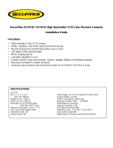
Step 3: Camera Installation
1. Determine the proper location on your vehicle to install the camera.
2. Make sure the area surface is clear, clean and flat.
3. Install the mounting bracket. (Refer to Diagram 3.1-1)
4. Assemble the camera inside of the mounting bracket (Refer to
Diagram 3.1-2)
5. Adjust the viewing direction and angles to attain the best viewing (Refer to
Diagram 3.1-3)
Diagram 3.1-1 Diagram 3.1-2 Diagram 3.1-3
④
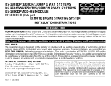
Step 4: Wire Connection
1. Connect the power source line to the camera. Also connect 20’ cable to the
monitor. (Refer to Diagram 4.1)
4 pin connector
Pin No.
PART-DESC
1 Video Output
2 Power DC 12V
3
GND
4
2
1
4
3
Diagram 4.1-1
Diagram 4.1-2
RED Power Input 12V(+)
BLACK Power Input 12(
-
)
Waterproof Camera
Connector
Video Output
Standard Cable Connector

1770 SOUTH TAPO STREET ª SIMI VALLEY, CALIFORNIA 93063
800-998-6880 ª 805-526-9400 ª FAX 805-581-9500
WWW.CRIMESTOPPER.COM
Page 5 of 6
Video output to monitor
Diagram 4.1-3
2. In most cases and as a time saver, connect the camera power wire at the rear of
vehicle behind the reverse lights. The red power wire line goes to the reverse
light + 12 V and the black wire to ground.
3. Please carefully choose a path to route and hide the camera cable. Drilling a cable
hole if necessary.
4. Please make sure to use the rubber grommet or plug to make a watertight seal for
the cable where it passes into the vehicle body.
5. Please refer to the monitor wiring diagram. The monitor must be connected using
its own power line and should not be connected to same power line with the
camera.
Step 5: Test Run Your New Rear View Camera System
1. You have just completed the installation and wiring of your new rear view camera
system.
2. Please make sure the vehicle is parked at a safe place before you do a test run.
3. Power up your vehicle and the monitor. Put the vehicle in reverse and the monitor
should immediately display a clear, color picture.
Important: The rear view camera will be used when the vehicle is in reverse gear. If the monitor
does not display a picture or the picture quality not satisfactory, please double check all cable
connections. If you are unable to correct the problem, please contact your supplier for help.
I/R Camera
Black, Ground
Red, power input 12V (+) from reverse light
12 PIN (M)
12 PIN (F)
4 PIN (M)
4 PIN (F)

1770 SOUTH TAPO STREET ª SIMI VALLEY, CALIFORNIA 93063
800-998-6880 ª 805-526-9400 ª FAX 805-581-9500
WWW.CRIMESTOPPER.COM
Page 6 of 6
Technical Specifications
The following table defines the technical specifications for the SV-6600 I/R Camera.
NTSC: 512(H)*492(V) ; PAL:512(H)*582(V)
Sensor 1/4 inch -type CCD Sensor
Signal processor Digital signal processor (D.S.P)
Resolution >250,000 pixels
Digitalis 10 bit A/D Converter
Sync. System Internal
Resolution More than 330 TV line
Minimum illumination 1.0 LUX / F2.8
S/N ratio More than 48dB
Gamma correction 0.45
Gain control AGC
White balance AUTO
Exposure A.E: auto electronics shutter 1/60s1/50s)~1/100000s
Video output 1.0Vp-p composite video. 75(OHM) load
Power consumption 180mA, 2.4W(MAX)
Operation temp
-30°C TO 75°C
Storage temp
-40°C TO 85°C
Lens mount type Wide-angle Board lens
Supply voltage DC12V, 220mA(+/-10%)
Horizontal Angle
Minimum 82.5°± 2°
Vertical Angle
Minimum 61.2°± 2°
Diagonal Angle
101°± 2
Housing Aluminum Alloy
IR spec
IR λ P=880 Typ.(nm) X 4
/