
MiniMe
P10 & P12
Models
Earthquake Sound Corporation
www.earthquakesound.com
Sound That Will Move You
User's Manual

Safety Instructions
13. Damage Requiring Service — The Component
1. Read Instructions — All the safety and operation
should be served only by EQ qualified serviced
instructions should be read before the Earthquake
personnel when:
Component is operated.
a. The power-supply cord or the plug has been
2. Retain Instructions — The safety and operating
damaged; or
instructions should be kept for future reference.
b. Objects have fallen, or liquid has spilled into the
3. Heed Warnings — All warnings on the
Component; or
Components in these operating instructions should be
followed.
c. The Component has been exposed to rain; or
4. Follow Instructions — All operating and other
d. The Component does not appear to operate
instructions should be followed.
normally or exhibits a marked change in performance;
or
5. Water and Moisture — The Component should not
be used near water - for example, near a bathtub,
e. The Component has been dropped, or its cabinet
washbowl, kitchen sink , laundry tub, in a wet
damaged.
basement, or near a swimming pool, etc.
14. Servicing — The user should not attempt to
6. Ventilation — The Component should be situated
service the Component beyond those means
so that its location or position does not interfere with
described in this operating manual. All other servicing
its proper ventilation. For example, the Component
should be referred to qualified Earthquake service
should not be situated on a bed, sofa, rug, or similar
personnel.
surface that may block any ventilation openings; or
placed in a built-in installation such as a bookcase or
15. To Prevent Electric Shock — Do not use this
cabinet that may impede the flow of air through
polarized plug with an extension cord, receptacles of
ventilation openings.
other outlet unless the blades can be fully inserted to
prevent blade exposure.
7. Heat — The Component should be situated away
from heat sources such as radiator, or other devices
16. Grounding or Polarization — Precautions should
which produce heat.
be taken so that the grounding or polarization means
of the Component is not defeated.
8. Power Sources — The Component should be
connected to a power supply only of the type
This apparatus does not exceed the Class A/Class B
described in these operation instructions or as marked
(which ever is applicable) limits for radio noise
on the Component.
emissions from digital apparatus as set out in the
radio interference regulations of the Canadian
9. Power Cord Protection — Power-supply cords
Department of Communications.
should be routed so that they are not likely to be
walked upon or pinched by items placed upon or
against them, paying particular attention to cords at
plugs, convenience receptacles, and the point where
they exit the Component.
10. Cleaning — The Components should be cleaned
only as recommended in this manual.
11. Non-use Periods — The power cord of the
Component should be unplugged from the outlet when
unused for a long period of time.
12. Object and Liquid Entry — Care should be taken
so that objects do not fall into and liquids are not
spilled inside of the Component.
The exclamation point within an
equilateral triangle is intended
to alert the user of the presence
of important operating and
maintenance (servicing)
instructions in the literature
accompanying the appliance.
The lightening flash with
arrowhead symbol within an
equilateral triangle is intended to
alert the user to the presence of
uninsulated "dangerous voltage"
within the product's enclosure,
that may be of sufficient
magnitude to constitute a risk of
electric shock to a person.
Earthquake • MiniMe User Manual
2

WARNING: The MiniMe subwoofers are capable of generating high sound pressure
levels. You should exercise caution when operating these speakers. Long term
exposures to high levels of sound pressure will cause permanent damage to your
hearing. Sound pressure levels exceeding 85dB can be dangerous with constant
exposure, set your audio system to a comfortable loudness level. Earthquake
Sound Corporation does not assume liability for damages resulting from the direct use
of the MiniMe subwoofers , and urges users to play volume at moderate levels.
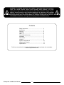
Contents
To find out more about this and other fine Earthquake products, please visit our website:
www.earthquakesound.com
Safety Instructions .................................................
Introduction ............................................................
Features .................................................................
Unpacking ..............................................................
Care .......................................................................
Control Panel Overview .........................................
Installation ..............................................................
Connections ...........................................................
Location .................................................................
System Configurations ...........................................
Adjusting the Controls ............................................
Specifications .........................................................
2
4
4
4
4
5
7
8
9
10
13
14
Earthquake • MiniMe User Manual
3

Introduction
Please take a moment to fill out and mail the
Earthquake Warranty Registration card. Also read the
serial number located on the control panel and record
it here:
Unpacking
Your Earthquake subwoofer should reach you
in perfect condition. If you do notice any shipping
damage, please contact your Earthquake dealer
immediately.
Gently lift out the unit and remove all the
packing material. It is important. It is important to save
all the packing materials and the box in case your
subwoofer ever needs to be moved or shipped for
repair.
Make sure that you keep your sales receipt. It
s the only way to establish the duration of you Limited
Warranty and it may be useful for insurance purposes.
Dear Valued Customer,
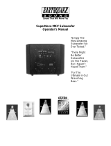
Welcome to the electric world of Earthquake
High Fidelity sound systems; you are about to
experience the MiniMe subwoofer. This system is
designed to dramatically enhance your enjoyment of
music and films at home, by adding power and
impact to low frequency sound effects, without taking
up your entire living space.
Earthquake Sound Corporation is located in
the heart of the Silicon Valley. It specializes in
manufacturing high end Home and Mobile audio
products ranging from the smallest driver to the loudest
subwoofer systems. In its dedication to excellence,
Earthquake has maintained extensive programs in
research and development to provide you with the
highest quality audio products made.
Features
• Elegant 7-layer piano black lacquer finish
This owners manual is designed to better
acquaint you with the MiniMe subwoofer system, and
• Built in 450-Watt, high efficiency, Class "D" amplifier
to guide you through the phases of system design and
application. It is imperative that you read this manual in
• Extremely low distortion
its entirety. EARTHQUAKE technicians and staff are
looking forward to answer any questions you might
• Long throw, premium quality drivers
have, please call (1-800-576-7944).
• Convenient compact size
• Automatic signal-sensing turn-on and stand-by mode
• Volume control
• Operation status LEDs
• 50Hz - 160Hz Freq. adjustment
• 0 - 180 Phase Shift adjustment
• High Level inputs
• Bypassed High Level outputs
• 220V - 110V selectable
Care
To maintain the speaker cabinet's finish, first
unplug the power cord and then use a soft, slightly
dampened cloth to clean the surfaces and finish off
with a dry cloth.
To keep the large rubber surrounds soft and
supple for 20-years or more, treat them with mink oil,
available ta most shoe repair stores. Rub a generous
amount into the surrounds with a soft cloth about once
a year (more often if you line in a dry climate).
Serial Number:
Purchased From:
Date:
Earthquake • MiniMe User Manual
4

(1) Line Level RCA Inputs terminals will accept up to 16-gauge quality speaker
Connect with RCA type patch cords to the line level wire. The Inputs should be connected to the left and
output of your receiver or pre-amp. If your pre- right speaker terminals of your amplifier or receiver.
amplifier or receiver has a single sub/LFE output, The Outputs should run from the subwoofer to the left
connect it to the subwoofer's left input jack. There is and right satellite speakers. Remember: Always
no need to use the subwoofers right input jack. If you connect red-to-red and black-to-black, when making
want to run your main/satellite speakers full range, connections between an amplifier/receiver to the
use a "Y" adapter at the pre-amplifier outputs. In this subwoofer. If you inadvertently reverse one of the
way, you can send the pre-amplifier's output signal to connections (i.e., red-to-black), you will notice a lack
your main amplifier and to the subwoofer at the same of bass from your subwoofer.
time.
(3) Voltage Selection Switch
(2) High Level Inputs / Outputs
Under normal conditions, the preferred connection is
through the Line Level inputs. If this is difficult or not
possible in your system, then you can use the
Speaker Level inputs. Also, if you experience
excessive noise or hum with the Line Level input,
often a simple change to the Speaker Level input will
result in a lower background noise level.
(4) Manual ON/OFF Switch
Connect the Speaker Level inputs to the speaker-level In the “ON” position, the subwoofer will remain “on”
outputs of your amplifier or receiver using speaker constantly or can turn “on” and “off” automatically
wire. The binding posts can accept bare wire when the “AUTO/ON” circuit is engaged. In the “OFF”
connections only. position, the subwoofer will remain off until the switch
is manually turned back to the “ON” position.
High Level: Connecting the Subwoofer using the high
level speaker connections: On the rear of your MiniMe (5) Line Fuse
Subwoofer are two pairs of red and black binding The subwoofer is supplied with a conservative, slow-
posts. One set is marked “Input” and one set is blow type fuse to protect the electronics.
marked “Output”, with each pair designated as left or
right. Each post is color-coded black/red. These
The voltage switch is positioned according to area
voltage requirements. It has been pre-set
prior to shipping from the factory.
CAUTION
Do not try to alter the voltage setting, as doing so will
result in a blown fuse. A wrong setting
may result in damaged electronics.
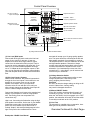
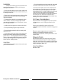
Control Panel Overview
Overview Continued On Next Page»
(5) Line Fuse
(9) 0-180° Phase Shift
(11) 50Hz - 160Hz
Frequency Adjustment
(12) Volume Control
(10) Sub Operation Switch
(8) Power Status LED
(1)
Inputs and Outputs
Line Level RCA
(7) Auto ON/OFF
(2) Speaker
Inputs and Outputs
Level
(4) Manual ON/OFF Switch(3) Voltage Selection Switch
(6) 110-120V AC Power Connection
Earthquake • MiniMe User Manual
5
Earthquake Sound, 2727 McCone Avenue, Hayward, CA 94545 USA
www.earthquakesound.com
VOLUME
FREQUENCY
MODE
PHASE
AUTO
MIN
50Hz
MAX
RIGHT
POWER
LEFT
160Hz
SUB
0
OFF
LFE
180
ON
110-120VAC~60Hz
220-240VAX~50Hz
FUSE: 115V, T6.4AL/250V
FUSE: 230V, T3.2AL/250V
ON
110-120V
220-240V
OFF
TO REDUCE RISK OF FIRE OR ELECTRIC SHOCK, DO NOT EXPOSE
THIS APPLIANCE TO RAIN OR MOISTURE NO USER SERVICEABLE
PARTS INSIDE. REFER SERVICING TO QUALIFIED SERVICE PERSONNEL
WARNING
WARNING: SHOCK HAZARD-DO NOT OPEN
AVIS: RISQUE DE CHOC ELECTRIQUE-NE PAS OUVRIR
RISK OF ELECTRIC SHOCK
DO NOT OPEN
CAUTION
P O W E R
DIGITAL
600 WATTS
POWERED
SUBWOOFER
FUSE

(6) Auto ON/OFF (10) Sub Operation Switch
When the main “POWER” ON/OFF switch is in the In LFE position, the Frequency adjustment becomes
“OFF” position, this switch has no affect on the disabled and the subwoofer runs in a Full range
subwoofer. When the main “POWER ON/OFF” switch mode, from 20Hz - 2kHz.
is in the “ON” position, this switch allows the auto
circuit to be engaged. When this switch is in the While in Sub position the subwoofer reverts to the
“AUTO” position, the subwoofer will automatically turn manual frequency adjustment, allowing the user to
“on” when it senses a signal. It will automatically turn operate and fine tune the subwoofer to their personal
“off” after 20 minutes with no signal. When this switch taste.
is in the “ON” position, the subwoofer will remain on
as long as the “POWER” ON/OFF switch is in the (11) 50Hz - 160Hz Frequency Adjustment
“ON” position. This controls the high frequency cutoff point. With the
control set to the middle, the subwoofer will reproduce
(7) 110-120V AC Power Connection frequencies up to 105Hz. If the control is set fully
The Earthquake MiniMe is equipped with a built in clockwise, the crossover is bypassed and the
standard, two-prong power connection. subwoofer will reproduce a wide frequency range.
With the control fully counter-closkcwise the
(8) Power Status LED subwoofer reproduces a narrow range, up to 50Hz.
Earthquake powered subwoofers have an LED on the
panel that indicates the status of the built-in amplifier. Rotate the control until the bass sound natural. If the
The LED will light red when the amplifier is in standby mid-bass sounds natural but you want more low bass,
mode and green when the amplifier is on and turn the control down a little.
receiving a signal.
(12) Volume Control
(9) 0-180° Phase Shift Manual volume control to regulate your subwoofers
This control is used to acoustically match the power output, to prevent clipping and distortions
subwoofer’s output to your main speakers. Select the caused by overpowering.
position, either 0° or 180°, in which your subwoofer
has more output at the listening position.
inspecting or changing the fuse. Never
use a fuse with a larger current rating
than recommended.
Always unplug the power cord before
Earthquake • MiniMe User Manual
6
Control Panel Overview Continued

• Do not let anything come into contact with the panel
Installation
and keep at least two inches away from any walls.
Observe the following general precautions and
read the safety instructions before powering your
The metal control plate serves as the amplifier heat
Earthquake subwoofer.
sink and also as a conduit to remove internal heat to
the outside and into the atmosphere. It can reach
• Never open the cabinet or remove the metal control
temperatures of 60° C, which will feel hot to the touch,
panel as this might result in an electrical shock to you,
using nerves of flesh and blood as temperature
or damage to the unit.
sensors. As uncomfortable as it may feel, 60 degrees
C cannot burn you, and in fact is almost cool to
• Protect it from prolonged exposure to direct sunlight
copper, silicon, steel, and aluminum the material from
and other direct sources of heat, such as heating
which your woofer is constructed.
vents and radiators.
AC Power Considerations
• To prevent fire or shock, do not expose the unit to
rain or moisture. If fluid or a foreign object should Ensure that the unit is plugged into an outlet capable
enter the unit, immediately turn off the power contact of supplying the correct voltage specified for your
your Earthquake dealer. model.
• Avoid excessive exposure to extreme cold or dust. Unplug your subwoofer's power cord from the
electrical outlet if it will be left unused for a long period
• Do not place heavy objects on top of the unit. of time.
• Do not place the subwoofer with its control panel
against the floor. Route the power-supply cord so it is not likely to be
walked on or pinched by especially at plugs,
• If you wish to place your woofer so the drivers face convenience receptacles, and the point where it exits
the floor and ceiling, thereby moving up and down, from the unit.
use at least 1-1 ½ inch high spikes or feet for support.
They may be attached either with screws or self-stick
Magnetic Fields
backing . This arrangement will impart substantial
We recommend that you place your woofer further
house and floor shaking motion.
than two feet away from your TV, VCR, DVD player,
tape deck or computer, so the speaker's magnet won't
distort the color of you TV picture or erase your video
Heat Rise
tapes, audio tapes, discs...etc.
• Allow adequate ventilation around the metal control
panel of the subwoofer.
Line Conditioner
DO NOT USE!
Earthquake • MiniMe User Manual
7

AC outlets on the same circuit breaker
Power strip
Tape Deck
DVD
Pre-amplifier
Amplifier
Subwoofer
Connections
• This diagram shows all the low power components
Please consider the following when setting up
sharing a power strip which is connected to the same
your new system:
outlet used by the amplifier.
• Before making or changing any connections,
• The subwoofer is connected to an outlet on the
ALWAYS make sure that the subwoofer is unplugged
same circuit breaker, provided that the total system
from the wall and your other components are turned
current draw does not exceed the breaker current
OFF. Also, turn down the volume control of the
rating.
subwoofer and your pre-amplifier or receiver.
• This arrangement will reduce the possibility of an
audible hum in your system caused by a ground loop.
• Whenever possible, keep the power cords away
from the signal cable or speaker wires to prevent any
hum or inference being heard in speakers.
• Choose reliable, high quality interconnect cables,
also called patch cords or RCA cables. They should
be fully shielded and as short as possible for the job.
The longest cable in your system will likely be to the
subwoofer, so choose a good quality brand.
• Some patch cords can be a very tight fit and there is
usually a preferred method of getting them off. Some
have to be removed with a twisting action. Be gentle
or you may damage the jacks of the subwoofer or
your other components.
Speaker Level Connections
• The subwoofer's Speaker Level Inputs can accept
speaker stripped speaker wires only.
• Make sure that the negative speaker wires never
touch the positive wires as this will short out and
possibly damage your amplifier or receiver.
Earthquake • MiniMe User Manual
8

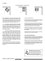
MiniMe
1
P= Passive Radiator A= Active Driver
MiniMe
2
P
A
MiniMe
3
PA
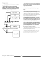
Location
Fact: Subwoofers reproduce frequencies with #1 is very good positioning.
wavelengths that are long in relation to the dimensions
of most living rooms. Standing waves will boost or #2 is also excellent but may shake the back wall too
cancel various frequencies due to the interaction with much and cause things on or along the walls to rattle too
the room boundaries. Moving a subwoofer in a room will much. If this occurs, use the #3 position.
change what you hear in the listening position a lot.
#3 Move the woofer approximately three feet away from
For maximum bass reinforcement, the MiniMe the right wall and place it along the back wall as shown.
subwoofer system should be placed in the corner of your This will substantially reduce the rattling of the back wall
living room, with the subwoofers facing the wall. This and will still pressurize the room with lots of bass.
creates acoustical coupling with the walls, which in turn
leads to a 9 decibels of boost in the overall response of Although low frequencies are non directional, factors
the MiniMe. Keep a 3" clearance between the such as room reflections, standing waves, resonance,
subwoofer and the walls. and absorption strongly affect your subwoofer's
performance.
Fine tuning the MiniMe requires adjustments to
the crossover point, volume control and the phase Also position the control panel so that it is not touching
switch. These controls are located on the side of the anything and can receive good ventilation.
enclosure. For ease of tuning we recommend that you
turn the MiniMe around to expose the controls, and
place it in position (corner). Set your stereo system to a
Using Two Subwoofers
moderate listening level and adjust the MiniMe
If you choose the use two woofers, the sound output will
accordingly. The MiniMe is equipped with a 24 dB / Oct.
double (an increase of ~5dB). Locate the woofers with
Low pass filter designed to eliminate vocals from
one in each corner and experiment with the location and
entering the system. When tweaking, gradually reduce
phase control to achieve the best bass response.
the crossover point setting to eliminate vocals from
seeping into the amplifier.
Always drive each woofer through the Left/Mon input
even though you are driving one woofer on a right
Your Earthquake MiniMe is designed to be placed in a
channel drive and the other with a left channel drive. If
corner and this will produce optimum performance.
your pre-amplifier has a single dub/LFE output, use a 'Y'
Experiment with at least two corners then decide which
cable to split it into two outputs.
is the best.
Remember to keep it at least two or
three feet away from any TV screen,
computer, VCR or magnetic tapes and
discs. This will reduce the chance of
the magnetic field upsetting the TV
screen or erasing your magnetic media.
Earthquake • MiniMe User Manual
9

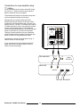
System Configurations
The following pages show some typical connections
that you might make in your installation. They show
how the inputs and outputs of the Earthquake sub are
connected to your pre-amplifier or receiver.
Connections to a pre-amplifier's
subwoofer output
If your pre-amplifier has a subwoofer output (often
labeled LFE for Low Frequency Effects), it can be
connected to the subwoofer's Left (Mono) input as
shown. This is the simplest and recommended
connection. A receiver with a sub/LFE output can be
connected in the same way.
The subwoofer will play the low frequency range and
the other speaker will play the frequency range
delivered to them by your amplifier.
If you have a home theater pre-amplifier, it may have
an independent subwoofer volume control. Make sure
this is correctly adjusted, and that the Earthquake
subwoofer's crossover frequency is set to 100Hz. This
is by no means an iron-clad rule, rather it is a good
starting point.
You can set the subwoofer's Bass Level control on
your receiver to 0dB, and then use the pre-amplifier's
subwoofer level control for normal and routine
adjustments.
PRE-AMPLIFIER
SUB/LFE OUT
L R
MAIN
OUTPUTS
+ -
AMPLIFIER
INPUTS
L R
TO FRONT SPEAKERS
+ -
Earthquake • MiniMe User Manual
10
Earthquake Sound, 2727 McCone Avenue, Hayward, CA 94545 USA
www.earthquakesound.com
VOLUME
FREQUENCY
MODE
PHASE
AUTO
MIN
50Hz
MAX
RIGHT
POWER
LEFT
160Hz
SUB
0
OFF
LFE
180
ON
110-120VAC~60Hz
220-240VAX~50Hz
FUSE: 115V, T6.4AL/250V
FUSE: 230V, T3.2AL/250V
ON
110-120V
220-240V
OFF
TO REDUCE RISK OF FIRE OR ELECTRIC SHOCK, DO NOT EXPOSE
THIS APPLIANCE TO RAIN OR MOISTURE NO USER SERVICEABLE
PARTS INSIDE. REFER SERVICING TO QUALIFIED SERVICE PERSONNEL
WARNING
WARNING: SHOCK HAZARD-DO NOT OPEN
AVIS: RISQUE DE CHOC ELECTRIQUE-NE PAS OUVRIR
RISK OF ELECTRIC SHOCK
DO NOT OPEN
CAUTION
P O W E R
DIGITAL
600 WATTS
POWERED
SUBWOOFER
FUSE

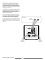
Connections to a pre-amplifier using
“Y” cables
If your pre-amplifier does not have a sub/LFE output,
you can use “Y” cables to send its main outputs to
both the subwoofer and your amplifier.
The subwoofer will play the low frequency range and
your front speakers will play the full range.
Although bass is commonly distributed evenly
between left and right channels (L+R bass), movie
soundtracks often contain differential (L-R) bass. The
opening scene in “Top Gun”, for example, has loads of
L-R bass information. If this is not preserved, the bass
in these scenes sounds anemic. The Earthquake
subwoofer utilized differential gain on the left and right
inputs to retain both the L+R and L-R information.
Therefore, systems which do not have a dedicated
sub/LFE output should use both the left and the right
inputs as shown, for the greatest bass impact.
An Alternative connection method without using “Y”
cables is shown on the next page.
If your pre-amp/receiver has a dedicated sub/LFE
output, the only the Left (Mono) input is used, as
shown on the previous page.
PRE-AMPLIFIER
L R
MAIN
OUTPUTS
+ -
AMPLIFIER
INPUTS
L R
TO FRONT SPEAKERS
+ -
Earthquake • MiniMe User Manual
11
Earthquake Sound, 2727 McCone Avenue, Hayward, CA 94545 USA
www.earthquakesound.com
VOLUME
FREQUENCY
MODE
PHASE
AUTO
MIN
50Hz
MAX
RIGHT
POWER
LEFT
160Hz
SUB
0
OFF
LFE
180
ON
110-120VAC~60Hz
220-240VAX~50Hz
FUSE: 115V, T6.4AL/250V
FUSE: 230V, T3.2AL/250V
ON
110-120V
220-240V
OFF
TO REDUCE RISK OF FIRE OR ELECTRIC SHOCK, DO NOT EXPOSE
THIS APPLIANCE TO RAIN OR MOISTURE NO USER SERVICEABLE
PARTS INSIDE. REFER SERVICING TO QUALIFIED SERVICE PERSONNEL
WARNING
WARNING: SHOCK HAZARD-DO NOT OPEN
AVIS: RISQUE DE CHOC ELECTRIQUE-NE PAS OUVRIR
RISK OF ELECTRIC SHOCK
DO NOT OPEN
CAUTION
P O W E R
DIGITAL
600 WATTS
POWERED
SUBWOOFER
FUSE
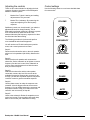
Using the line speaker-level inputs
If you are using a receiver which does not have a
subwoofer output or line level outputs (pre-outs), you
can connect its speaker outputs to the subwoofer's
Speaker-Level inputs. The front speakers can still be
connected to your receiver.
The subwoofer's internal amplifier supplies the power
to reproduce the low frequency range. It receives a
sample of the signal going to your front speakers. (An
insignificant fraction of your receiver's power is
transferred to the subwoofer).
There is no need to use the Speaker Level inputs if
you are using a separate amplifier and pre-amplifier.
Such systems are best connected using the Line
Level Inputs as shown in the previous diagrams.
If you are using the Line Level inputs and there is an
excessive amount of noise or hum present, using the
Speaker Level inputs may yield a lower background
noise level.
Earthquake • MiniMe User Manual
12
FRONT
SPEAKERS
FRONT
SPEAKERS
+ -
RECEIVER
MAIN
OUTPUTS
L R
+ -

AUTO
OFF ON
VOLUME
FREQUENCY
MODE
PHASE
MIN
50Hz
MAX
160Hz
SUB
0
LFE
180
Adjusting the controls
There are two main methods for adjusting the level,
crossover frequency and phase of the Earthquake
MiniMe to match a system.
? Method One: Typical: Listening and making
adjustments to suit your taste.
? Method Two: Laboratory: By measuring the
output and adjusting for a flat frequency
response.
Satisfactory results can be achieved if you make the
adjustments based on simply listening. This is
Earthquake's preferred method as it allows the system
to be voiced based on what sounds the best,
whereas laboratory-flat frequency response can often
be clinical and less than exciting.
The following procedure is for those who prefer a
more methodical and scientific approach.
You will need a test CD with low-frequency warble
tones, and a sound pressure-level meter.
Step #1
Disconnect the subwoofer and run the main speaker
with a tone in its passband (80-100Hz). Measure the
level.
Step #2
Disconnect the main speaker and reconnect the
subwoofer. Set the subwoofer to its highest crossover
frequency. Set the level control of the subwoofer to
give the same sound pressure level with the same
tone you used in Step #1.
Step #3
With both the subwoofer and the main speaker
connected, measure the level of the tones at the
available frequencies. Because the crossover is set
too high, you will have a peaked response. Adjust the
crossover control to get the smoothest response.
Step #4
Use the phase control to make the response even
smoother. It has its biggest effect at the crossover
frequency. You can iterate between the crossover and
the phases controls. Keep your hands off the level
control! It was set correctly in Step #2.
Step #5
Listen to the subwoofer. Resist all temptation to turn
up the level control. Play something with really deep
bass to confirm that your subwoofer is working.
Control settings
Use the following charts to record more desirable data
from test results.
Earthquake • MiniMe User Manual
13

MiniMe P10 Specifications MiniMe P12 Specifications
Amplifier Output Amplifier Output
600 Watts (4-Ohm impedance) 600 Watts RMS (4-Ohm impedance)
High Cut Filter High Cut Filter
50Hz-160Hz adjustable. The crossover can 50Hz -160Hz adjustable. The crossover can
be bypassed by rotating the crossover be bypassed by rotating the crossover
frequency control fully clockwise. frequency control fully clockwise.
Frequency Response Frequency Response
20Hz - 135Hz 18Hz - 115Hz
Power Line Voltage Power Line Voltage
110-220V~AC / 50 - 60Hz / 720 WATTS 110-220V~AC / 50 - 60Hz / 720 WATTS
Dimensions (HxWxD) Dimensions (HxWxD)
12-1/4” / 311.15mm (including legs) 14-3/4” / 374.65mm (including legs)
11-3/8” / 288.925mm (+.75" with amplifier 14-1/8” / 358.775mm (+.75" with amplifier
controls) controls)
13-3/8” / 339.725mm (grille-to-grille) 16-3/8” / 415.925mm (grille-to-grille)
Weight Weight
30.5 Lbs 40 Lbs
Finish Finish
Piano Black Piano Black
Output Levels Output Levels
Greater than 108dB peak SPL (includes room Greater than 108dB peak SPL (includes room
gain) from 20Hz to 90Hz. gain) from 18Hz to 90Hz.
Input Sensitivity For Full Output Input Sensitivity For Full Output
240mVrms using single RCA with GAIN & 240mVrms using single RCA with GAIN &
CROSSOVER controls at MAX, Using Two CROSSOVER controls at MAX, Using Two
RCAs 90mVrms with VOLUME control fully RCAs 90mVrms with VOLUME control fully
clockwise. clockwise.
Input Impedance Input Impedance
8.2 kilo-Ohm Line-level inputs 8.2 kilo-Ohm Line-level inputs
32-Ohm Speaker-level inputs 32-Ohm Speaker-level inputs
Driver Driver
10” high-power with extra large magnet and 12” high-power with extra large magnet and
long throw mechanical design yield very high long throw mechanical design yield very high
back emf. The result is extraordinarily high back emf. The result is extraordinarily high
operating efficiency that is, more acoustic operating efficiency that is, more acoustic
output for each watt of input. output for each watt of input.
Internal System Gain Internal System Gain
42dB 42dB
Earthquake • MiniMe User Manual
14

Limited 5-Year Warranty
Earthquake warrants the original purchaser that all Factory Sealed New Audio Products to be free from defects in material
and workmanship under normal and proper use for a period of five (5) years from the date of purchase (as shown on the
original bill of sale with serial number affixed/written on it). The five (5) year warranty period is valid only if an authorized
Earthquake dealer properly installs the product and the warranty registration card is properly filled out and sent to
Earthquake Sound Corporation. If a non-authorized party installs the product, a ninety (90) day warranty period will be
applied.
(A) Five (5) years limited warranty plan coverage guidelines:
? First year: Earthquake pays for labor, parts, and ground freight (only in US mainland, not including Alaska and
Hawaii. Shipping to us is not covered).
? Second year: Earthquake pays for labor and parts only, customer must pay freight both ways.
? Third, fourth & fifth year: Earthquake pays labor only. Customer must pay for parts and freight both ways.
(B) Warning:
Products (sent for repair) that are tested by Earthquake technicians and deemed to have no problem(s) will not be
covered by the five (5) year limited warranty. Customer will be charged a minimum of one (1) hour of labor (at the ongoing
rates) plus shipping charges back to customer.
(C ) Earthquake will repair or replace at our option all defective products/parts subject to the following
provisions:
? Defective products/parts have not been altered or repaired by other than an Earthquake factory-approved technicians.
?Products/parts are not subjected to negligence, misuse, improper use or accident, damaged by improper line voltage,
used with incompatible products or have its serial number or any part of it altered, defaced or removed, or have been
used in any way that is contrary to Earthquake's written instructions.
(D) Warranty Limitations: Warranty does not cover products that have been modified or abused, including but not limited
to the following:
? Damages to speaker cabinet and cabinet finish due to misuse, abuse or improper use of cleaning materials/methods.
?Bent speaker frame, broken speaker connectors, holes in speaker cone, surround & dust cap, burnt speaker voice
coil.
?Fading and/or deterioration of speaker components & finish due to improper exposure to elements.
?Bent amplifier casing, damaged finish on the casing due to abuse, misuse or improper use of cleaning material.
?Burnt tracers on PCB.
?Product/part damaged due to poor packaging or abusive shipping conditions.
?Subsequent damage to other products.
A warranty claim will not be valid if the warranty registration card is not properly filled & returned to Earthquake with a
copy of the sales invoice. Warranty card is located on the last page of this manual.
(E) Service Request:
To receive product service, contact Earthquake Service Department at (510) 732-1000 and request an RMA number
(Return Material Authorization). Items shipped without a valid RMA number will be refused. Make sure you provide us with
your complete/correct shipping address, a valid phone number, and a brief description of the problem you are
experiencing with the product. In most cases, our technicians might be able to resolve the problem over the phone; Thus,
eliminating the need to ship the product.
(F) Shipping Instructions:
Product(s) must be packaged in its original protective box(es) to minimize transport damage and prevent repackaging cost
(at the ongoing rates). Shipper claims regarding items damaged in transit must be presented to carrier. Earthquake Sound
Corporation reserves the right to refuse improperly packed product. Original bill of sale must accompany product returned
to service. We encourage you to include with the package a written description of the problem. Ship product to:
Earthquake Sound Corp. 2727 McCone Avenue, Hayward, CA 94545. Ph: (510) 732-1000. You are responsible for the
cost of shipping the product to Earthquake Sound Corporation.
(G) Disputes Resolution:
All disputes between clients and Earthquake Sound Corporation resulting from the five (5) year limited warranty policy
must be resolved according to the laws & registration of the county of Alameda California.
Earthquake • MiniMe User Manual
15
Easily Register Your New Products Here» www.earthquakesound.com/form_reg.htm

Earthquake Sound Corporation
2727 Mc Cone Avenue,
Hayward, California 94545
Ph (510) 732-1000
Fax (510) 732-1095
www.earthquakesound.com
-
 1
1
-
 2
2
-
 3
3
-
 4
4
-
 5
5
-
 6
6
-
 7
7
-
 8
8
-
 9
9
-
 10
10
-
 11
11
-
 12
12
-
 13
13
-
 14
14
-
 15
15
-
 16
16


EarthQuake MiniMe P10 User manual
- Category
- Subwoofers
- Type
- User manual
Ask a question and I''ll find the answer in the document
Finding information in a document is now easier with AI
Related papers
-
 Earthquake Sound MiniMe FF8 User manual
-
 Earthquake Sound MiniMe P8V2 P8WV2 Owner's manual
-
 Earthquake Sound IQ-52P User manual
-
Earthquake Sound Supernova MKIV-10 User manual
-
 Earthquake Sound 600W.2 User manual
-
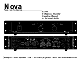 Earthquake Sound Nova PA-600 Operation manual User manual
-
Earthquake Sound 600WRMS User manual
-
 Earthquake Sound DB-10 User manual
-
 Earthquake Sound DJ Quake 2.1 User manual
-
 Earthquake Sound T500W/2 User manual


Other documents
-
 Earthquake Sound Nova FF6.5 Owner's manual
-
OSD Audio BLACK TREVOCE 12 Owner's manual
-
MK Sound VX-850 User manual
-
Acoustic Research ARS115PSB User manual
-
Pyle PDIC4CBTL4B Installation guide
-
-
 Earthquake Sound MiniMe FF8V2 Owner's manual
-
 Earthquake Sound ACS3.0 Owner's manual
-
AIRPULSE C-9 Owner's Information
-
 Aaron SW-400 Operating instructions


