Page is loading ...

Earthquake Sound reserves the right to amend details of the specifications without notice.
Copyright © Earthquake Sound Corporation
Earthquake Sound Corporation • 2727 McCone Avenue Hayward CA, 94545 • Tel 510-732-1000
TNT Series Amplifiers
Owners Manual
T500W/2
T1000W/2
T2000W/4
T2000WD/1
TD5X
MODELS:
Sound That Will Move You.
Sound That Will Move You.

Our Thank You................................................................................
Cautions and Advisories.................................................................
Signal Sensing Feature..................................................................
Specifications.................................................................................
Adjustments and Installation:
T500W/2 (2-Channel Class A/B)...............................................
T1000W/2 (2-Channel Class A/B).............................................
T2000W/4 (4-Channel Class A/B).............................................
T2000WD/1 (Mono Class D).....................................................
TD5X (Full Range + Mono Class D).........................................
THANK YOU
Thank you for choosing Earthquake Sound’s line of TNT amplifier: the best way to
enhance your
factory mobile audio system. With proper installation and responsible listening, your amplifier(s)
will give you years of near perfect sound reproduction.
We strongly recommend you to have your new amplifier(s) installed by an authorized Earthquake
Sound dealer. Installation professionals employed by your dealer have the correct tools and
knowledge to install your amplifier(s) neatly and successfully. Also, when your new products are
installed by an authorized dealer, your product will include a FIVE (5) YEAR LIMITED
WARRANTY. If you choose to perform your own installation, your warranty will be subject to
limitations. Dealer policies on handling warranty requests may vary from one dealer to the next.
Please read the warranty information in its entirety and use good judgment when making these
vital decisions.
TABLE OF CONTENTS
2 3
2
2
3
4 - 5
6 - 7
8 - 9
10 - 11
12 - 13
14 - 15
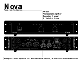
Earthquake Amplifiers are capable of generating high sound pressure levels. You should
exercise caution when operating these amplifier systems. Long term exposures to high
levels of sound pressure will cause permanent damage to your hearing. Sound pressure levels
exceeding 85dB can be dangerous with constant exposure. Set your audio system to a comfortable
loudness level. Earthquake Sound Corporation does not assume liability for damages resulting from the
direct use of Earthquake amplifiers or other Earthquake products and urges users to play their music at
moderate listening levels.
3
2
1 - 1 1/2
1
1/2
1/4 or less
8
6
4
97
100
102
105
110
115
90
92
95
THE CHART (ON THE SIDE) SHOWS THE U.S.
GOVERNMENTS OCCUPATIONAL SAFETY AND
HEALTH ADMINIS T R AT ION (OSHA)
REGULATIONS WHICH WERE IN EFFECT AT
THE TIME OF THIS PUBLICATION FOR
PERMISSIBLE NOISE EXPOSURE, PER
29CFR1910.95, TABLE G-16.
SOUND LEVEL DBA
DURATION IN HOURS
CAUTION:
SIGNAL SENSING FEATURE - AUTO ON/REMOTE ON
This TNT amplifier features the new, improved and more powerful circuitry. Better yet,
Earthquake Sound has added a special AUTO SIGNAL SENSING Feature which allows
installers to turn on the amplifier without using the remote wire.
By simply connecting the RCA or Speaker level inputs to the amplifier, it will turn on
automatically when it senses an audio signal. This feature makes upgrading the sound
system in many of the latest model vehicles easier for installers as it eliminates the need to
connect a remote turn on wire to the amplifier.
Before you proceed, please note the following:
!
This feature may not be compatible with all latest model vehicles.
!
If your vehicle is going to be parked for over 4 weeks, then you should disconnect the
main fuse of the amplifier.
!
Be sure to follow the connection instructions and illustrations below.
AUTO ON
When the switch is on AUTO ON, the amplifier will
automatically detect an incoming signal when the stereo is
turned on. If the amplifier does not detect any signal after 20
minutes, the amplifier will automatically turn off.
The proper power and remote wire connection when using the AUTO SIGNAL SENSING is
illustrated below.
DO NOT connect the remote wire to the head unit as this will damage your sound system.
RESET
In case the system goes into protection, simply turn off the
audio source, lower the volume and slide the switch to RESET
then back to AUTO ON position.
REMOTE ON
When the switch is on REMOTE ON, the amplifier relies on the
remote wire to detect the signal and turn the amplifier on or off.
NOTE: RCA outputs must be inserted in CH1/2 for the amplifier to detect any incoming
signal.
GND
REM
(–)
BAT
(+)
POWER
X
to battery
to head unit
4-gauge
16-gauge
GND
REM
(–)
BAT
(+)
POWER
4-gauge
to battery
16-gauge
Specifications Are Subject To Change Without Notice www.earthquakesound.com

4 5
SPECIFICATIONS
Model
T500W/2
T1000W/2
T2000W/4
T2000WD/1
TD5X
Class
A/B
A/B
A/B
D
D
Number of Channels
2
2
4
1 Mono
4 Full Range + 1 Mono
Max Power Output
800 Watts
1400 Watts
2000 Watts
2000 Watts
3000 Watts
Max Power 4-Ohm Bridged
1 x 400
1 x 700
2 x 250
1 x 1000 @ 2Ω
2 x 100 @ 4Ω +
1 x 300 @ 4Ω
Max Power 4-Ohm Stereo
2 x 150
2 x 300
4 x 100
1 x 600 @ 4Ω
4 x 100 @ 4Ω^ +
1 x 600 @ 2Ω
THD @ 4-Ohm
THD @ 2-Ohm
> 0.01%
> 0.05%
> 0.01%
> 0.05%
> 0.01%
> 0.05%
> 0.01%
> 0.016%
> 0.01%
> 0.016%
Channel Separation
> 60 dB
> 60 dB
Crossover Frequency, LPF
Crossover Frequency, HPF
Crossover Frequency, SUB
50 - 250 Hz
50 - 250 Hz
N/A
50 - 250 Hz
50 - 250 Hz
N/A
50 - 250 Hz
50 - 250 Hz
N/A
N/A
N/A
50 - 300 Hz
40 - 400 Hz
40 - 400 Hz
40 - 160 Hz
Bass Boost
0 - 18 dB
0 - 18 dB
0 - 18 dB
0 - 10 dB
N/A
Fuse
1 x 30 Amp
2 x 25 Amp
2 x 20 Amp
2 x 30 Amp
3 x 25 Amp
Signal-to-Noise Ratio
95 dB Below Rated Power
95 dB Below Rated Power
Dimensions (H x W x D)
2-1/4” x 9-3/4” x 9”
2-1/4” x 9-3/4” x 13-5/16”
2-1/4” x 9-3/4” x 13-3/8”
2-1/4” x 9-3/4” x 11”
2-1/4” x 9-3/4” x 16-3/8”
Net Weight
4.25 lbs
6.4 lbs
6.5 lbs
6 lbs
9 lbs
* Dimensions include plugs, terminals and mounting feet.
^ Minimum impedance is 4Ω.
Specifications Are Subject To Change Without Notice www.earthquakesound.com
Please refer to the warranty guidelines provided with the
amplifier. It is recommended that you keep a copy of your sales
receipt and note your serial number here for future reference.
SERIAL NUMBER

6 7
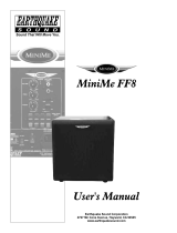
T500W/2
Set Xover switch
to FULL
K-10, ten-inch bass tube, in mono
application (4 Ohms minimum)
7.0V
17.0V
4.0V
10.0V
2.5V
5.0V
1V
1V
The gain knob is not a volume
control. It is designed to match
the input level of the amp to the
output level of the source unit.
Over driving "clipping" the input
stage of the amp will cause
damage to the amplifier (please
refer to table for setting).
MAX INPUT
VOLTAGE
BEFORE
CLIPPING
RCA LEVEL
SPEAKER
LEVEL
250Hz
210Hz170Hz125Hz
90Hz
50Hz
XOVER
KNOB
SETTING
T500W/2
One
30A
fuse
To car chassis / ground
To remote turn on / trigger
To battery positive (+)
Bridgeable Speaker
outputs, minimum
4-Ohms mono.
MODE SELECTOR:
This feature tells the
amplifier to run in
either HIGH PASS,
FULL RANGE or
LOW PASS MODE
LEVEL ADJUST:
Allows the amplifier to deliver a controlled
maximum sound level into selected
channel(s) when the volume is turned to
max. This acts as a volume limiter for the
system, preventing you from over driving
the speakers or subwoofers.
LOW LEVEL INPUTS:
Low level inputs
range of 0.2V to 5V RMS.
This is where the front and
rear RCA outputs from your
head unit or other devices
are inserted.
with a
R C A l i n e
th r o ugh to
c a s c a d e
a n o t h e r
amplifier.
N o X o v e r
point.
2-WAY 12dB/Oct
VARIABLE XOVER:
C o n t r o l t h e
corresponding channels
cutoff frequencies. This
feature is disabled when
in FULL RANGE
This information applies to
both HPF and LPF
FC6.2 FC6.2
FC6.2 Xover FC6.2 Xover
FC6.2 MidrangeFC6.2 Midrange
AUTO SIGNAL
SENSING:
Please refer to page 3 for
explanation of this
feature.
HIGH LEVEL
INPUT:
Speaker level
inputs with a
range of 0.5V
to 17V RMS.
BASS BOOST:
0 - 18dB Bass
Boost for use
w i t h
subwoofers.
AUTO ON REMOTE ONRESET
POWER LED:
When LED is on, it
indicates that the
amplifier is ON and
f u n c t i o n i n g
properly.
PROTECTION (PROT) LED:
If LED comes on then you have an
issue that requires service. Turn
off the amplifier and call
Earthquake for further assistance.
See warranty for details.
Specifications Are Subject To Change Without Notice www.earthquakesound.com

8 9
T1000W/2
Set Xover switch
to FULL
K-10, ten-inch bass tube, in mono
application (4 Ohms minimum)
Two
25A
fuses
To car chassis / ground
To remote turn on / trigger
To battery positive (+)
Bridgeable Speaker
outputs, minimum
4-Ohms mono.
7.0V
17.0V
4.0V
10.0V
2.5V
5.0V
1V
1V
The gain knob is not a volume
control. It is designed to match
the input level of the amp to the
output level of the source unit.
Over driving "clipping" the input
stage of the amp will cause
damage to the amplifier (please
refer to table for setting).
MAX INPUT
VOLTAGE
BEFORE
CLIPPING
RCA LEVEL
SPEAKER
LEVEL
XOVER
KNOB
SETTING
T1000W/2
250Hz
210Hz170Hz125Hz
90Hz
50Hz
FC6.2
Tweeter
FC6.2
Tweeter
FC6.2 Xover FC6.2 Xover
FC6.2 MidrangeFC6.2 Midrange
AUTO ON REMOTE ONRESET
LOW LEVEL INPUTS:
Low level inputs
range of 0.2V to 5V RMS.
This is where the front and
rear RCA outputs from your
head unit or other devices
are inserted.
with a
AUTO SIGNAL
SENSING:
Please refer to page 3 for
explanation of this
feature.
MODE SELECTOR:
This feature tells the
amplifier to run in
either HIGH PASS,
FULL RANGE or
LOW PASS MODE
LEVEL ADJUST:
Allows the amplifier to deliver a controlled
maximum sound level into selected
channel(s) when the volume is turned to
max. This acts as a volume limiter for the
system, preventing you from over driving
the speakers or subwoofers.
R C A l i n e
th r o ugh to
c a s c a d e
a n o t h e r
amplifier.
N o X o v e r
point.
2-WAY 12dB/Oct
VARIABLE XOVER:
C o n t r o l t h e
corresponding channels
cutoff frequencies. This
feature is disabled when
in FULL RANGE
This information applies to
both HPF and LPF
HIGH LEVEL
INPUT:
Speaker level
inputs with a
range of 0.5V
to 17V RMS.
POWER LED:
When LED is on, it
indicates that the
amplifier is ON and
f u n c t i o n i n g
properly.
PROTECTION (PROT) LED:
If LED comes on then you have an
issue that requires service. Turn
off the amplifier and call
Earthquake for further assistance.
See warranty for details.
Specifications Are Subject To Change Without Notice www.earthquakesound.com
BASS BOOST:
0 - 18dB Bass
Boost for use
w i t h
subwoofers.

10 11
T2000W/4
Bridgeable Speaker
outputs, minimum
4-Ohms mono.
Set Xover switch
to FULL
K-10, ten-inch bass tube, in mono
application (4 Ohms minimum)
CH3 CH4
CH3 CH4
CH1 CH2
CH1 CH2
To car chassis / ground
To remote turn on / trigger
To battery positive (+)
Two
20A
fuses
7.0V
17.0V
4.0V
10.0V
2.5V
5.0V
1V
1V
The gain knob is not a volume
control. It is designed to match
the input level of the amp to the
output level of the source unit.
Over driving "clipping" the input
stage of the amp will cause
damage to the amplifier (please
refer to table for setting).
XOVER
KNOB
SETTING
T2000W/4
MAX INPUT
VOLTAGE
BEFORE
CLIPPING
RCA LEVEL
SPEAKER
LEVEL
250Hz
210Hz170Hz125Hz
90Hz
50Hz
FC6.2 Midrange FC6.2 Midrange
FC6.2 Xover FC6.2 Xover
FC6.2
Tweeter
FC6.2
Tweeter
FC6.2 Midrange FC6.2 Midrange
FC6.2 Xover FC6.2 Xover
FC6.2
Tweeter
FC6.2
Tweeter
AUTO ON REMOTE ONRESET
LOW LEVEL INPUTS:
Low level inputs
range of 0.2V to 7V RMS.
This is where the front and
rear RCA outputs from your
head unit or other devices
are inserted.
with a
AUTO SIGNAL
SENSING:
Please refer to page 3 for
explanation of this
feature.
LEVEL ADJUST:
Allows the amplifier to deliver a controlled
maximum sound level into selected
channel(s) when the volume is turned to
max. This acts as a volume limiter for the
system, preventing you from over driving
the speakers or subwoofers.
MODE SELECTOR:
This feature tells the
amplifier to run in
either HIGH PASS,
FULL RANGE or
LOW PASS MODE
R C A l i n e
th r o ugh to
c a s c a d e
a n o t h e r
amplifier.
N o X o v e r
point.
2-WAY 12dB/Oct
VARIABLE XOVER:
C o n t r o l t h e
corresponding channels
cutoff frequencies. This
feature is disabled when
in FULL RANGE
This information applies to
both channels 1/2 and 3/4
HIGH LEVEL
INPUT:
Speaker level
inputs with a
range of 0.5V
to 17V RMS.
POWER LED:
When LED is on, it
indicates that the
amplifier is ON and
f u n c t i o n i n g
properly.
PROTECTION (PROT) LED:
If LED comes on then you have an
issue that requires service. Turn
off the amplifier and call
Earthquake for further assistance.
See warranty for details.
Specifications Are Subject To Change Without Notice www.earthquakesound.com
BASS BOOST:
0 - 18dB Bass
Boost for use
w i t h
subwoofers.

12 13
T2000WD/1
SUBSONIC FILTER:
For the vast majority of
vehicles, peaks or dips
occur at about 40Hz –
around the frequency of
a low bass guitar note.
Use this control to
correct that peak or dip.
PHASE SHIFT:
This 0 - 180° phase
shift adjustment is
for reversing the
phase output with
respect to its input.
LOW PASS FILTER (LPF):
This 50Hz - 300Hz low-
pass filter blocks unwanted
high frequencies for
cleaner low-frequencies.
8-gauge
speaker
outputs
REMOTE SUB LEVEL:
Allows you to limit the
bass output
from a location of your
choice. Using a screw
mounted remote control.
amplifier’s
Two
30A
fuses
To car chassis / ground
To remote turn on / trigger
To battery positive (+)
The gain knob is not a volume
control. It is designed to match
the input level of the amp to the
output level of the source unit.
Over driving "clipping" the input
stage of the amp will cause
damage to the amplifier (please
refer to table for setting).
7.0V
17.0V
4.0V
10.0V
2.5V
5.0V
1V
1V
SUB
XOVER
SETTING
MAX INPUT
VOLTAGE
BEFORE
CLIPPING
RCA LEVEL
SPEAKER
LEVEL
300Hz
240Hz210Hz150Hz
70Hz
50Hz
AUTO ON REMOTE ONRESET
AUTO ON REMOTE ONRESET
AUTO ON REMOTE ONRESET
LOW LEVEL INPUTS:
Low level inputs
range of 0.2V to 7V RMS.
This is where the front and
rear RCA outputs from your
head unit or other devices
are inserted.
with a
AUTO SIGNAL
SENSING:
Please refer to
p a g e 3 f o r
explanation of this
feature.
0 - 10dB
BASS
BOOST
CONTROL
POWER LED:
When LED is on, it
indicates that the
amplifier is ON and
f u n c t i o n i n g
properly.
PROTECTION (PROT) LED:
If LED comes on then you have an
issue that requires service. Turn
off the amplifier and call
Earthquake for further assistance.
See warranty for details.
LEVEL ADJUST:
Allows the amplifier to deliver a
controlled maximum sound level into
selected channel(s) when the volume
is turned to max. This acts as a
volume limiter for the system,
preventing you from over driving the
speakers or subwoofers.
R C A l i n e
th r o ugh to
c a s c a d e
a n o t h e r
amplifier.
N o X o v e r
point.
HIGH LEVEL
INPUT:
Speaker level
inputs with a
range of 0.5V
to 17V RMS.
Specifications Are Subject To Change Without Notice www.earthquakesound.com

OUTPUT
CH2+
CH2-
CH2+ CH4+ CH5-
CH2- CH4- CH5+
CH2- CH4-
FRONT
BRIDGED BRIDGED
CH1-
CH1+
CH1-
CH3-
CH1+
CH3+
CH1+
CH3+
SUB
-
+
CH4+
CH4-
REAR
CH3-
CH3+
FC6.2 Mid-Range
FC6.2 XoverFC6.2 Xover
FC6.2
Tweeter
FC6.2
Tweeter
FC6.2 Mid-Range
Focus EQ-693 Focus EQ-693
The Sub Channel Will Accept
2 or 4-Ohm Subwoofers
14 15
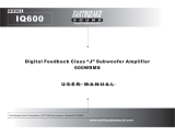
TD5X
To car chassis / ground
To remote turn on / trigger
To battery positive (+)
Three
25A
fuses
Bridgeable speaker outputs,
minimum 4-Ohms, plus
subwoofer connection.
FUSESGND REMOTE
POWER
OUTPUT
+12V
CH2+
CH2-
CH2- CH4-
FRONT
BRIDGED BRIDGED
CH1-
CH1+
CH1+
CH3+
SUB
-
+
CH4+
CH4-
REAR
CH3-
CH3+
25A 25A 25A
PROT
PWR
SUB INPUT:
This is your
s u b w o o f e r
channel where
the sub RCA
outputs from
your head unit
are inserted.
INPUT SELECTOR:
This tells the amp to play all channels even if only one pair of
RCAs is connected. EXAMPLE: If the head unit only has one
pair of RCA outputs then you must plug them into the CH1/2
connections and set the switch to 2. This tells the amp that you
are using one set of RCAs and it needs to play all five channels
regardless. If you have four RCAs, then set it to 4 and so on.
CH3/4
FULL
LOW
HIGH
MIN MAX
LEVEL
400Hz40Hz
XOVER
Set Xover switch to FULL (full range)
Set Xover to desired setting and set Mode
switch to HIGH (high-pass). Level
adjustment should be dialed in by ear. Keep
it at MIN and slowly work your way up.
CH1/2
FULL
LOW
HIGH
MIN MAX
LEVEL
400Hz40Hz
XOVER
TD5X
40Hz 280Hz
100Hz
180Hz 400Hz360Hz
SUB
XOVER
SETTING
7.0V
4.0V 2.5V
1V
MAX INPUT
VOLTAGE
BEFORE
CLIPPING
The gain knob is not a volume control.
It is designed to match the input level of
the amp to the output level of the source
unit. Over driving "clipping" the input
stage of the amp will cause damage to the
amplifier (please refer to table for setting).
RCA LEVEL
POWER (PWR) LED:
When LED is on, it indicates that the
amplifier is ON and functioning properly.
PROTECTION (PROT) LED:
If LED comes on then you have an issue that requires
service. Turn off the amplifier and call Earthquake for
further assistance. See warranty for details.
SUB XOVER:
The
Xover provides
control over the
device cutoff
frequency.
0-18dB/Oct
REMOTE
SUB
LEVEL:
Allows you to
adjust
bass output
i n t e n s i t y
remotely.
amps
LOW INPUTS:
These are CH1/2(FRONT)
& 3/4(REAR) low inputs
with a range of 0.2V to
7V RMS. This is where
the front and rear RCA
outputs from your head
unit are inserted.
R
L
L
R R
L
GAIN
HP LPFR
XOVER
GAIN
XOVER
5
4
2
AUTO ON REMOTE ON
RESET
CHANNEL 1/2 SIGNAL FLOW
CHANNEL 3/4 SIGNAL FLOW MONO CHANNEL 5 SIGNAL FLOW
40
MIN
MAX
160
REMOTE
SUBWOOFER CONTROL CHANNEL 1/2 CONTROL CHANNEL 3/4 CONTROL
INPUT SELECTOR
HP LPFR
40
MIN
MAX
400
GAIN
XOVER
40
MIN
MAX
400
2
1
4
3
MODE MODE
MODE SELECTOR:
This feature tells the
amplifier to run in
either HIGH PASS,
FULL RANGE or
LOW PASS MODE
LEVEL ADJUST:
Control the max output of
each channel. The LEVEL
controls its respective
channel regardless how
many inputs in use.
VARIABLE XOVER:
C o n t r o l t h e
corresponding channels'
cutoff frequencies. This
feature is disabled when
in FULL RANGE.
This information applies to
both channels 1/2 and 3/4
LEVEL ADJUST:
Allows the amplifier to deliver a
controlled maximum sound
level into selected channel(s)
when the volume is turned to
max. This acts as a volume
limiter for the system,
preventing you from over
driving the speakers or
subwoofers.
AUTO SIGNAL
SENSING:
Please refer to
p a g e 3 f o r
explanation of this
feature.
Specifications Are Subject To Change Without Notice www.earthquakesound.com
/