Dormakaba SAFLOK MT Operating instructions

Type
Operating instructions
SAFLOK MT
Installation Instructions
All parts needed to install your SAFLOK MT are included with each unit.
Check to make sure all parts are accounted for before you begin installation.
Do not substitute any of the parts, as it can result in poor performance of your lock.
A60580,
SPINDLE ASSEMBLY
A22230,
ROTATION LIMITER
A20650,
CAM PRIVACY
A27200,
8 EA. SCREW END CAP
M2.9 X 1
A22240, PLATE BACKING, UPPER
A24120, CHASSIS INNER DIE CAST
A23010,
2 EA. END CAP-INNER STANDARD
A28110,
BATTERY PACK
A27010,
4 EA. SCREW TRIM MOUNTING
M5 X 0.8
A22010-L-COLOR,
ESCUTCHEON, I/S STANDARD
A22020-L-COLOR,
ESCUTCHEON, I/S ADB
A27000,
2 EA. SCREW COVER
MOUNTING M4 X 0.7
51540-COLOR,
THUMB-TURN
A26030,
SPRING, BATTERY
A27030, 3 EA.
SCREW PCB M2.9 X 1
A23220,
BUSHING-INNER
A22290,
PLATE BACKING, LOWER
A27060,
2 EA. RETAINING RING, LEVER
A28520,
POTTED PCB
A24000, 2 EA. LEVER-TROY
A24010, 2 EA. LEVER-CONTINENTAL
A24020, 2 EA. LEVER-TUBULAR
A24030, 1 EA. LEVER-VINTAGE RH
A24040, 1 EA. LEVER-VINTAGE LH
A24050, 2 EA. LEVER-ARC
A24090, 2EA. LEVER-GALA
54450,
PUSH WASHER
STANDARD, 29900
ADB, 54460
WAVE WASHER
A20490
SPINDLE
ASSEMBLY
A26010, SPRING LEVER RETURN
Interior
Assembly
A22270,
BACK PLATE
A20480,
CARD READER ASSEMBLY
(RIBBON NOT SHOWN)
A20500,
CHASSIS OUTER ASSEMBLY
A23000,
2 EA. END CAP-OUTER
STANDARD
A22000-L-COLOR,
ESCUTCHEON,
O/S KEY OVERRIDE
A25020,
BUSHING-BRASS
A23210,
BUSHING-OUTER
A27070,
RETAINING RING, BEARING
A26010,
2 EA. SPRING, LEVER RETURN
A60580,
SPINDLE
ASSEMBLY
A27060,
RETAINING RING, LEVER
A22230,
ROTATION LIMITER
Exterior
Assembly
Step 1
Door Preparation
• For new construction installations, the door manufacturer
shall prepare the door using the SAFLOK MT Door Prep. Template
(see MT Door Prep. Template). The door edge prep. is a standard
full mortise prep. for a 1-1/4˝ x 8˝ front plate (a 1˝ x 8 ˝ and
1˝ x 7-3/4˝ custom front is available). The door surface holes
are customized for the SAFLOK trim.
Step 2
Door Preparation -
Retrofit
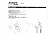
• For retrofit installations, remove the existing hardware and
assure that the door edge prep. is appropriate for the SAFLOK
mortise lock (see Fig. 1). Position and clamp the drill fixture
onto the door. The fixture has two positioning posts that rest
inside the 1-1/4˝ x 8˝ x 15/16˝ deep mortise pocket,
establishing the proper backset for the trim.
When the fixture is clamped, its surfaces should be parallel
with the door surfaces and door edge. Drill the holes from
both sides without disturbing the fixture’s position. One 3/4˝
hole needs to be on the inside door surface only. Remove the
fixture and complete the rectangular cutout by sawing or
grinding between the four holes. Also, notch material on the
inside surface for easier routing of the motor wire. After
machining, remove debris from the mortise cutouts.
Step 3
Mortise Case Installation
The mortise front plate has an adjustable bevel. Align the
front plate to the bevel of the door edge and tighten the two
bevel adjust screws at the top and bottom of the mortise case.
Position the mortise case in the door edge with the motor wire
routed out the notch (see Fig. 2). Use care to ensure the motor
wires do not get pinched or pulled as the mortise is inserted
into the pocket.
• Fully tighten the two #12 screws to firmly attach the
mortise front to the door. Under no circumstances should
these screws be left loose or tightened after the lock trim
is installed. (If this ever seems necessary, the door prep.
machining is incorrect.) Install the strike and scalp plates
with the screws provided and test for proper mechanical
latch engagement into the strike plate.
Step 4
Lock Trim Installation
• Both the outside and inside trim assemblies have 1/4˝
alignment pins that fit into holes in the mortise case.
These pins establish an accurate trim position with respect
to the mortise case assembly, allowing the levers and bolt
mechanism to operate freely without binding. The holes
machined in the door surfaces should not influence the trim’s
position. There should be clearance between the features of
the outside trim and the door prep. holes. If the outside trim
fits tightly because the through bolt posts or card reader
enclosure rubs on the door prep. holes, then remove the
mortise and enlarge the holes to achieve a free fit. Under
no circumstances should the 1/4˝ alignment pins be bent
or removed to allow a free fit (see Fig. 3).
• Position the outside trim on the door with the card reader
ribbon cable passing through the rectangular cutout. Use a
card so the ribbon cable does not get pulled or cut. On metal
doors, it may be necessary to deburr the inside rectangular
NOTCH BETWEEN
HOLES FOR WIRE CLEARANCE
MOTOR WIRE
CHANNEL
MORTISE CASE
ALIGNMENT
PIN
SPINDLE
SPRING
ALIGNMENT
HOLES
SPINDLE
ALIGNMENT
PIN
OUTSIDE TRIM
INSIDE TRIM
MOTOR
WIRE
INSIDE
DOOR
SURFACE
#12 MORTISE
SCREWS
2-3/4˝ x 1-5/8˝ CUTOUT
1-1/4˝ x 8˝ x 15/64˝ DEEP
3/4˝ REQUIRED ON
INSIDE ONLY
INSIDE DOOR
SURFACE
NOTCH FOR WIRE
ROUTING
2-3/4˝ BACKSET
(FIG. 1)
(FIG. 2)
(FIG. 3)
ALIGNMENT PINS
SPINDLE
SPRING
SPINDLE
DEAD BOLT
SPINDLE
ASSEMBLY
BATTERY
M5 X 30mm
SCREWS
M5 X 30mm
SCREWS
GREEN
GROUND
WIRE
BATTERY
WIRE
RIBBON
MOTOR
WIRE
hole or insulate the bottom edge of the rectangular hole with
a piece of tape (see Fig. 4). SAFLOK spacer plates will be
required for doors less than 1-3/4˝ thick.
• Feed the ribbon cable and motor wire through the
appropriate channel and holes in the back plate and position
the back plate onto the door surface with the alignment pins
inserted into the mortise case holes. Check for a free fit and
ensure the back plate is resting flat on the door without
pinching the motor wire. Install four M5 flathead bolts and
tighten. When using a power screwdriver, use caution to
avoid cross threading and over torquing (see Fig. 5).
• Insert the ribbon into the ribbon connector (see Fig. 6).
Do not bend the ribbon sharply. Route the excess ribbon
upward over the battery (see Fig. 7).
• Connect the motor wire, then battery wire (if not factory
attached) to the PCB as shown (see Fig. 5).
The indicator mark on the switch cam should face
6:00 for the standard application and 3:00 for the ADB
application (see Fig. 6). Insert the dead bolt spindle assembly
into the switch cam. The retaining ring should rest on
the switch cam when fully inserted. (Proper position of
the cam will allow the door to be opened when the
dead bolt is retracted and block entry when the dead bolt
is thrown for privacy. Emergency keys will override this
electronic double lock). Install the inside escutcheon
with the dead bolt thumb-turn pointed up. Fasten with
two flathead M4 torx screws provided (see Fig. 8).
Program the lock using the Lock Programmer &
Interrogator (LPI) probe provided with the key encoding
system. After programming the lock, test for proper
function using appropriate keys per the instructions
in the programming manual.
Step 5
Test Lock Functionality
• Insert a construction zone level keycard. The green
light should flash nine times while the exterior handle
becomes operable for use. If it does not, the table
below has the most likely responses.
M4 X 16mm TORX SCREWS
CARD READER
RIBBON CABLE
Insulate any
sharp metal
edges.
Assure that wire
is not pinched
or strained.
(FIG. 4)
(FIG. 5)
(FIG. 8)
Route
ribbon
upward
over
battery.
(FIG. 6)
(FIG. 7)
Lock Communication Electronic Function Description
12 yellow blinking lights Switch cam not aligned properly.
2 yellow blinking lights Keycard not allowed.
OR
Keycard cancelled out by newer
construction level keycard.
9 Red blinking lights and Low battery condition –
alternating red and green lights change the battery.
2 yellow and red simultaneously Bad track read or keycard data
blinking lights corrupted – may require a
new access card.
9 simultaneously red and green Date not set – use LPI to
blinking LEDs reset date and time.
2 red blinking lights Keycard not read (possibly upside
down, wrong end, wrong key).
MT INSTALL NB - 10/07
SAFLOK DOOR UNIT INSPECTION CRITERIA
Appearance
• Finish is free of blemishes or scratches that would distract from
lock appearance
• Lock body and underplate (if used) is mounted straight on the door
• Door scalp is mounted straight and flush with door edge
• Jamb strike is mounted straight and is flush with the jamb face
• Correction of minor blemishes on the door jamb are the responsibility
of the property’s maintenance department
Lock Function
• Knob or lever rotates and moves freely
• Lever is horizontal to floor when at rest position
• Dead bolt extends fully and retracts without binding (door open)
• Lock latch and dead bolt engage jamb strike plate freely
• Anti-pick latch locks latch when depressed (door open)
• Anti-pick latch is depressed when the contact is made with the
strike plate (door closed)
Electronics/Keycards
• Keycard can be inserted and withdrawn freely
Yellow light flashes twice when incorrect keycard is used
• Double red flash if keycard is used wrong, so it cannot be read
(or wrong card is used, i.e. credit card)
Green light appears when proper keycard is used
Green light flashing when lever is operated
Green light continues to flash for a five-second cycle
Yellow light flashes 12 times when the dead bolt is extended and
guest/ hotel keycard is used
• Dead bolt release functions properly when “E” (emergency) key
is used
• All keycards function per specifications and property-designed
master plan
Door Function
• Door closes and latches with little or no interference
• Dead bolt extends fully through the strike plate without interference
(door closed)
• Spacing between door edge and inside door jamb does not exceed
3/16˝ (door closed)
Note: If bumpers or other seals are added after strike
plate installation and cause alignment and latch problems,
this becomes the property’s responsibility to correct (generally
applies to new construction or new door installation).
Questions? Contact Customer Service at 800.999.6213.
  • Page 1 1
  • Page 2 2
  • Page 3 3
  • Page 4 4

Dormakaba SAFLOK MT Operating instructions

Type
Operating instructions

Ask a question and I''ll find the answer in the document

Finding information in a document is now easier with AI