Page is loading ...

Pilot Light Ignition
Installation
and Service Guide
Agricultural Animal Confinement Building Heaters
150-22003

Foreword
The purpose of this Service Guide is to provide detailed
instructions and information for the installation, maintenance,
troubleshooting and repair of L.B. White pilot ignition agricultural
heaters. By consulting specific sections within the guide, you
will become acquainted with components and operation of the
equipment as well as proper procedures to use during trouble
analysis and repair. Parts illustrations and information for all
L.B. White pilot ignition heaters is included. Illustrations in the
various sections may not necessarily depict the actual heater
model and are intended for reference only.
It is very important when using the guide to pay particular
attention to any Warning or Caution statements printed
throughout the guide, identifying areas where care must be
exercised.
This Service Guide covers the majority of problems which may
arise. However, as with any product, certain problems may be
encountered which have not been covered. If such problems
arise, please call Technical Service at 1-800-345-7200 from
7:00 a.m. to 5:00 p.m. Central Standard Time to address these
problem areas.
It is L.B. White’s policy to continually upgrade our service
network, therefore, new ideas and comments are welcomed for
incorporation into this guide.

WARNING
Fire and Explosion Hazard
■ Not for home or recreational vehicle use.
■ Installation of this heater in a home or
recreational vehicle may result in a fire or
explosion.
■ Fire or explosions can cause property
damage or loss of life.
FOR YOUR SAFETY
If you smell gas:
■ Open windows.
■ Don't touch electrical switches.
■ Extinguish any open flame.
■ Immediately call your gas supplier.
FOR YOUR SAFETY
Do not store or use gasoline or other
flammable vapors and liquids in the vicinity
of this or any other appliance.
WARNING
Fire and Explosion Hazard
■ Keep solid combustibles a safe distance
away from the heater.
■ Solid combustibles include wood or paper
products, feathers, straw, and dust.
■ Do not use the heater in spaces which
contain or may contain volatile or airborne
combustibles.
■ Volatile or airborne combustibles include
gasoline, solvents, paint thinner, dust
particles or unknown chemicals.
■ Failure to follow these instructions may
result in a fire or explosion.
■ Fire or explosions can lead to property
damage, personal injury or loss of life.
GENERAL HAZARD WARNING
■ Failure to comply with the precautions and instructions provided within this guide, can
result in:
— Death
— Serious bodily injury or burns
— Property damage or loss from fire or explosion
— Asphyxiation due to lack of adequate air supply or carbon monoxide poisoning
— Electrical shock
■ Read this Service Guide before installing or servicing this heater.
■ Only properly-trained service people should repair or install L.B. White heaters.
■ Replacement labels are available at no charge. For assistance, contact L.B. White at
1-800-345-7200.
WARNING
■ Proper gas supply pressure must be provided to the inlet of the heater.
■ Refer to dataplate for proper gas supply pressure.
■ Gas pressure in excess of the maximum inlet pressure specified at the heater inlet can cause
fires or explosions.
■ Fires or explosions can lead to serious injury, death, building damage or loss of livestock.
■ Gas pressure below the minimum inlet pressure specified at the heater inlet may cause
improper combustion.
■ Improper combustion can lead to asphyxiation or carbon monoxide poisoning and therefore
serious injury or death to humans and livestock.

Table of Contents
Section 1 General Information Section/Page
Basic Unit Description and Application . . . . . . . . . . . . . . . . . . . . . . . . . . . . . . . . . . . .1.1
Key Markings; Purpose and Location . . . . . . . . . . . . . . . . . . . . . . . . . . . . . . . . . . . . . .1.1
Heater Specifications . . . . . . . . . . . . . . . . . . . . . . . . . . . . . . . . . . . . . . . . . . . . . . . . . . .1.2
Safety Precautions . . . . . . . . . . . . . . . . . . . . . . . . . . . . . . . . . . . . . . . . . . . . . . . . . . . . .1.3
Section 2 Installation Instructions
General . . . . . . . . . . . . . . . . . . . . . . . . . . . . . . . . . . . . . . . . . . . . . . . . . . . . . . . . . . . . . .2.1
Gas Supply
- Pipe Sizing . . . . . . . . . . . . . . . . . . . . . . . . . . . . . . . . . . . . . . . . . . . . . . . . . . . . . . . .2.2
- Tank Sizing . . . . . . . . . . . . . . . . . . . . . . . . . . . . . . . . . . . . . . . . . . . . . . . . . . . . . . .2.3
- Tank Location and Installation . . . . . . . . . . . . . . . . . . . . . . . . . . . . . . . . . . . . . . .2.4
- LP Gas Tank Manifolding . . . . . . . . . . . . . . . . . . . . . . . . . . . . . . . . . . . . . . . . . . . .2.5
- Manual Shut-Off Valve, Hose and Regulator Assembly . . . . . . . . . . . . . . . . . . . .2.6
- Sediment Trap . . . . . . . . . . . . . . . . . . . . . . . . . . . . . . . . . . . . . . . . . . . . . . . . . . . . .2.7
Electrical Supply
- Requirements . . . . . . . . . . . . . . . . . . . . . . . . . . . . . . . . . . . . . . . . . . . . . . . . . . . . .2.8
- Thermostat Wiring
Models:
346/348, 377/379, 408/410 . . . . . . . . . . . . . . . . . . . . . . . . . . . . . . . . .2.9-1
AS040 . . . . . . . . . . . . . . . . . . . . . . . . . . . . . . . . . . . . . . . . . . . . . . . . . . . . .2.9-2
AB200 and AB250 . . . . . . . . . . . . . . . . . . . . . . . . . . . . . . . . . . . . . . . . . .2.9-3
Indoor Installation
- Hanging Instructions . . . . . . . . . . . . . . . . . . . . . . . . . . . . . . . . . . . . . . . . . . . . . .2.10
- Air Diverters
Two-Piece . . . . . . . . . . . . . . . . . . . . . . . . . . . . . . . . . . . . . . . . . . . . . . . . . . . .2.11-1
One-Piece . . . . . . . . . . . . . . . . . . . . . . . . . . . . . . . . . . . . . . . . . . . . . . . . . . . .2.11-2
Section 3 Operation Instructions
Start-Up and Shut-Down . . . . . . . . . . . . . . . . . . . . . . . . . . . . . . . . . . . . . . . . . . . . . . . .3.1
Variable Heat Output . . . . . . . . . . . . . . . . . . . . . . . . . . . . . . . . . . . . . . . . . . . . . . . . . . .3.2
Section 4 Preventative Maintenance
Periodic Inspection . . . . . . . . . . . . . . . . . . . . . . . . . . . . . . . . . . . . . . . . . . . . . . . . . . . . .4.1
Cleaning Instructions . . . . . . . . . . . . . . . . . . . . . . . . . . . . . . . . . . . . . . . . . . . . . . . . . . .4.2
Section 5 Troubleshooting Instructions
Troubleshooting Guide . . . . . . . . . . . . . . . . . . . . . . . . . . . . . . . . . . . . . . . . . . . . . . . . . .5.1
Section 6 Component Testing
Voltage Checks . . . . . . . . . . . . . . . . . . . . . . . . . . . . . . . . . . . . . . . . . . . . . . . . . . . . . . . .6.1
Continuity Checks . . . . . . . . . . . . . . . . . . . . . . . . . . . . . . . . . . . . . . . . . . . . . . . . . . . . . .6.2
Thermocouple and Power Unit Tests . . . . . . . . . . . . . . . . . . . . . . . . . . . . . . . . . . . . . .6.3
High Limit Switch Tests . . . . . . . . . . . . . . . . . . . . . . . . . . . . . . . . . . . . . . . . . . . . . . . . .6.4
Section 7 Wiring Diagrams
Electrical Connection and Ladder Diagram . . . . . . . . . . . . . . . . . . . . . . . . . . . . . . . . .7.1


Basic Unit Description and Application
Pilot ignition agricultural building heaters are direct-fired,
non-vented heaters used in the heating of animal
confinement buildings (examples: swine, chicken, and
turkey). These heaters utilize a system that ignites the gas
by a conventional pilot flame rather than by direct spark or a
hot surface igniter. L.B. White offers you the most
dependable pilot system in the industry. Tested and proven
over time, these heaters provide simple yet reliable
operation.
As a non-vented heater, adequate ventilation must be
provided to ensure fresh air for combustion and removal of
combustion by-products from the building.
This style of heater is offered in a wide range of input ratings,
some with variable heat control, to help manage heating
needs efficiently.
All heaters referred to in this guide are to be mounted inside
the building at appropriate locations to help provide proper
warm air flow in the room being heated.
Key Markings; Purpose and Location
Markings constitute safety related information such as the
dataplate, start-up/shut-down instructions, warnings, etc.
that are applied on the heater to allow the qualified service
person or end user to operate the heater in a safe manner.
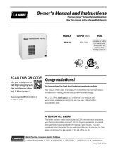
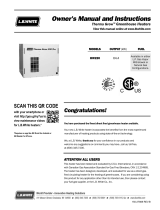
A. Dataplate
Purpose:
Used for identification of model number, and
configuration number and also critical information
such as safe clearances to combustibles, burner
manifold pressure, maximum and minimum
allowable inlet pressures, etc.
Typical Location:
Interior or exterior of burner end access panel.
Part No.:
Varies with design sequence and model number.
Contact L.B. White Co.
B. Start Up and Shut Down Procedures
Purpose:
Provides the basic information to safely start up and
shut down the heater and also provides cautionary
information relative to various safety aspects of
installation and application.
Typical Location:
Next to dataplate.
Part No.:
150-20158
Familiarize yourself with the location and content of all
markings. Location may vary depending on model. If any
markings are damaged or unreadable, replace the markings
immediately. Contact the L.B. White Company.
General
Information
August 1999
MODEL AW060
CONFIGURATION NO. AHPD210000
SERIAL NO.:
L. B. WHITE CO., INC. W6636 L.B. WHITE ROAD ONALASKA, WI 54650 608/783-5691
A
GS
D
E
S
I
G
N
C
E
R
T
I
F
I
E
D
A
A
A
M
E
R
I
C
N
S
S
O
C
I
A
T
I
O
N
MAXIMUM INPUT: 60,000 BTUH
TYPE FUEL: PROPANE VAPOR WITHDRAWAL
BURNER MANIFOLD PRESSURE 10.0 IN W.C. AT MAXIMUM INPUT
ELECTRICAL: 115 VOLTS A.C. 60 HZ SINGLE PHASE 1.5 AMPS
MIN. CLEARANCES FROM HEATER TO ADJACENT COMBUSTIBLE MATERIALS: REAR 1 FT SIDES 1 FT
TOP TO CEILING 1 FT BLOWER OUTLET 6 FT AND FUEL CONTAINER 6 FT
VENTILATION: 240 CFM OF AIR REQUIRED TO SUPPORT COMBUSTION.
MAXIMUM 13.5 INCHES W.C. AND MINIMUM 11.5 INCHES W.C. GAS SUPPLY PRESSURE
ACCEPTABLE AT INLET 0F HEATER FOR PURPOSE OF INPUT ADJUSTMENT.
POSITION HEATER AWAY FROM LIVESTOCK
AGRICULTURAL BUILDING HEATER
1.1-11
AB250
250,000

Heater Specifications
General
Information
1.2-11
August 1999
SPECIFICATIONS
Maximum Input (BTUH) 60,000 115,000 170,000 40,000
Minimum Input (BTUH) N/A N/A N/A 15,000
250 CFM 600 CFM 760 CFM 220 CFM
10.5 in. 7.0 in. 11.0 in. 7.0 in. 11.0 in. 7.0 in.
W.C. W.C. W.C. W.C. W.C. W.C.
10.0 in. W.C. 4.0 in. W.C. 10.0 in. W.C. 4.0 in. W.C. 10.0 in. W.C. 4.0 in. W.C. N/A N/A
11.5 in. 3.6 in. 11.5 in. 4.5 in. 11.5 in. 4.5 in. 11.5 in. 3.6 in.
W.C. W.C. W.C. W.C. W.C. W.C. W.C. W.C.
11.5 in. 3.6 in. 11.5 in. 4.5 in. 11.5 in. 4.5 in. 11.5 in. 3.6 in.
W.C. W.C. W.C. W.C. W.C. W.C. W.C. W.C.
11 in. W.C. 3.4 in. W.C. 11 in. W.C. 4 in. W.C. 11 in. W.C. 4 in. W.C. 11 in. W.C. 3.5 in. W.C.
2.78 lbs. 60 cu. ft. 5.32 lbs. 115 cu. ft. 7.87 lbs. 170 cu. ft. 1.85 lbs. 40 cu. ft.
.69 lbs. 15 cu. ft.
1/12 H.P. 1/5 H.P. 1/3 H.P. 1/30 H.P.
1700 RPM 1100 RPM 1100 RPM 1725 RPM
3.0 6.0 6.5 4.5
1.0 1.6 2.2 1.5
21
1/4 x 11 1/4 x 24 23 x 16 1/2 x 24 24 x 19 x 30 21 1/4 x 14 1/2 x 16 3/4
TOP
SIDES
BACK
BLOWER
OUTLET
GAS L.P. Gas Supply — 6 ft. (1.83 m)
SUPPLY Natural Gas Supply — N/A
55 90 110 39
61 100 129 43
346 348 377 379 408 410 AS040
L.P. Natural L.P. Natural L.P. Natural L.P. Natural
Gas Gas Gas Gas Gas Gas Gas Gas
MMooddeell
Ventilation Air Required
to Support Combustion
Net Weight (lbs.)
Shipping Weight (lbs.)
Electrical Supply
(Volts/Hz/Phase)
Amp Draw
Dimensions (Inches)
L x W x H
STARTING
CONTINUOUS
OPERATION
Motor Characteristics
Fuel Consumption
Per Hour
Heaters Using
Control Valves
With Internal
Low Pressure
Regulator and
Gas Shut Off
Inlet GGas
Supply
Pressure
Burner
Manifold
Pressure
Heaters Using
Control Valves
Less Internal
Low Pressure
Regulator and
Gas Shut Off
(Control Valve
Part #500-
02309)
MAX.
MIN.
MAX.
MIN.
13.5 in. W.C. N/A
Sleeve Bearing
N/A N/A N/A
N/A
N/A N/A
Ball Bearing
4 ft.
6 in.
6 in.
6 in.
6 in.
6 in.
6 in.
1 ft.
1 ft.
1 ft.
115/60/1
Minimum Safe
Distances From
Nearest
Combustible
Materials
N/A
N/A
Inlet GGas
Supply
Pressure
Burner
Manifold
Pressure
MAX.
MIN.
6 ft.

Heater Specifications
General
Information
August 1999
SPECIFICATIONS
Maximum Input (BTUH) 200,000 250,000
Minimum Input (BTUH) N/A 160,000
760 CFM 1100 CFM
11.5 in. 7.0 in.
W.C. W.C.
10.0 in. 4.0 in.
W.C. W.C.
11.5 in. 4.5 in.
W.C. W.C.
11.5 in. 4.5 in.
W.C. W.C.
11 in. 4.0 in.
W.C. W.C.
9.26 200 11.57 250
lbs. cu. ft. lbs. cu. ft.
7.41 16 0
lbs. cu. ft.
1/5 H.P. 1/3 H.P.
1100 RPM 1075 RPM
12 14.5
4.0 4.8
24
3/4 x 20 x 30 30 3/4 x 18 1/4 x 28 1/4
TOP 1 ft.
SIDES 1 ft.
BACK 1 ft.
BLOWER
OUTLET
GAS L.P. Gas Supply — 6 ft. (1.83 m)
SUPPLY Natural Gas Supply — N/A
98 109
120 126
AB200 AB250
L.P. Natural L.P. Natural
Gas Gas Gas Gas
MMooddeell
Ventilation Air Required
to Support Combustion
Net Weight (lbs.)
Shipping Weight (lbs.)
Electrical Supply
(Volts/Hz/Phase)
Amp Draw
Dimensions (Inches)
L x W x H
Minimum Safe
Distances From
Nearest
Combustible
Materials
STARTING
CONTINUOUS
OPERATION
Motor Characteristics
Fuel Consumption
Per Hour
MAX.
MIN.
Ball Bearing
6 ft.
115/60/1
N/A
N/A
N/A
N/A
N/A
N/A N/A
N/A N/A
N/A N/A
N/A N/A
1.2-22
Heaters Using
Control Valves
With Internal
Low Pressure
Regulator and
Gas Shut Off
Inlet GGas
Supply
Pressure
Burner
Manifold
Pressure
Heaters Using
Control Valves
Less Internal
Low Pressure
Regulator and
Gas Shut Off
(Control Valve
Part #500-
02309)
MAX.
MIN.
13.5 in. W.C.
Inlet GGas
Supply
Pressure
Burner
Manifold
Pressure
MAX.
MIN.

Safety Precautions
General
Information
1.3-11
August 1999
LP ggas aand nnatural ggas hhave mman-mmade oodorants aadded sspecifically ffor ddetection oof ffuel ggas lleaks.
If aa ggas lleak ooccurs, yyou sshould bbe aable tto ssmell tthe ffuel ggas.
THAT’S YYOUR SSIGNAL TTO GGO IINTO IIMMEDIATE AACTION!
■ Do not take any action that could ignite the fuel gas. Do
not operate any electrical switches. Do not pull any
power supply or extension cords. Do not light matches
or any other source of flame. Do not use your telephone.
■ Get everyone out of the building and away from the area
immediately.
■ Close all propane (LP) gas tank or cylinder fuel supply
valves, or the main fuel supply valve located at the meter
if you use natural gas.
■ Propane (LP) gas is heavier than air and may settle in low
areas. When you have reason to suspect a propane
leak, keep out of all low areas.
■ Natural gas is lighter than air and can collect around
rafters or ceilings.
■ Use your neighbor’s phone and call your fuel gas
supplier and your fire department. Do not re-enter the
building or area.
■ Stay out of the building and away from area until
declared safe by the firefighters and fuel gas supplier.
■
FINALLY,
let the fuel gas service person and the
firefighters check for escaped gas. Have them air out
the building and area before you return. Properly trained
service people must repair the leak, check for further
leakages, and then relight the appliance for you.
WARNING
■ Do not use this heater for heating human living quarters.
■ Do not use in unventilated areas.
■ The flow of combustion and ventilation air must not be
obstructed.
■ Proper ventilation air must be provided to support the
combustion air requirements of the heater being used.
■ Refer to the specification section of this guide, the
heater’s Owner’s Manual, heater dataplate, or contact
the L.B. White Company to determine combustion air
ventilation requirements of the heater.
■ Lack of proper ventilation air will lead to improper
combustion.
■ Improper combustion can lead to carbon monoxide
poisoning in humans leading to serious injury or death.
Symptoms of carbon monoxide poisoning can include
headaches, dizziness and difficulty in breathing.
■ Symptoms of improper combustion affecting livestock
can be disease, lower feed conversion, or death.
Asphyxiation HHazard
■
Some ppeople ccannot ssmell wwell. SSome ppeople ccannot
smell tthe oodor oof tthe mman-mmade cchemical aadded tto
propane ((LP) oor nnatural ggas. YYou mmust ddetermine iif yyou
can ssmell tthe oodorant iin tthese ffuel ggases.
■ Learn to recognize the odor of propane (LP) gas and
natural gas. Local propane (LP) gas dealers and your
local natural gas supplier (utility) will be more than
happy to give you a scratch and sniff pamphlet. Use it to
become familiar with the fuel gas odor.
■ Smoking can decrease your ability to smell. Being
around an odor for a period of time can affect your
sensitivity to that particular odor. Odors present in
animal confinement buildings can mask fuel gas odor.
■
The oodorant iin ppropane ((LP) ggas aand nnatural ggas iis
colorless aand tthe iintensity oof iits oodor ccan ffade uunder
some ccircumstances.
■ If there is an underground leak, the movement of gas
through the soil can filter the odorant.
■ Propane (LP) gas odor may differ in intensity at different
levels. Since propane (LP) gas is heavier than air, there
may be more odor at lower levels.
■
Always bbe ssensitive tto tthe sslightest ggas oodor.
If you
continue to detect any gas odor, no matter how small,
treat it as a serious leak. Immediately go into action as
discussed previously.
FUEL GAS ODOR
ODOR FADING -- NO ODOR DETECTED
ATTENTION -- CRITICAL POINTS TO REMEMBER!
■ Propane (LP) gas and natural gas have a distinctive odor.
Learn to recognize these odors. (Reference Fuel Gas
Odor and Odor Fading sections above.
■
If you have not been properly trained in repair and service
of propane (LP) gas and natural gas fueled heaters, then
do not attempt to light heater, perform service or repairs,
or make any adjustments to the heater on propane (LP)
gas or natural gas fuel system.
■ Even if you are not properly trained in the service and
repair of the heater, ALWAYS be consciously aware of the
odors of propane (LP) gas and natural gas.
■ A periodic “sniff test” around the heater or at the
heater’s joints; i.e. hose, connections, etc., is a good
safety practice under any conditions. If you smell even a
small amount of gas, CONTACT YOUR FUEL GAS
SUPPLIER IMMEDIATELY. DO NOT WAIT!

Safety Precautions
General
Information
1. Do not attempt to install, repair, or service this heater
or the gas supply line unless you have continuing
expert training and knowledge of gas heaters.
Qualifications for service and installation of this
equipment are as follows:
a.
To be a qualified gas heater service person, you
must have sufficient training and experience to
handle all aspects of gas-fired heater installation,
service and repair. This includes the task of
installation, troubleshooting, replacement of
defective parts and testing of the heater. You must
be able to place the heater into a continuing safe
and normal operating condition. You must
completely familiarize yourself with each model
heater by reading and complying with the safety
instructions, labels, Owner’s Manual, etc., that is
provided with each heater.
b.
To be a qualified gas installation person, you must
have sufficient training and experience to handle
all aspects of installing, repairing and altering gas
lines, including selecting and installing the proper
equipment, and selecting proper pipe and tank
size to be used. This must be done in accordance
with all local, state and national codes as well as
the manufacturer’s requirements.
2. All installations and applications of L.B. White heaters
must meet all relevant local, state and national codes.
Included are L.P. gas, natural gas, electrical, and
safety codes. Your local fuel gas supplier, a local
licensed electrician, the local fire department or
similar government agencies, or your insurance agent
can help you determine code requirements.
a. For U.S.A. installations and applications:
-- ANSI/NFPA 58, latest edition, Standard for
Storage and Handling of Liquefied Petroleum
Gas and/or
-- ANSI Z223.1/NFPA 54, National Fuel Gas Code
-- ANSI/NFPA 70, National Electrical Code.
b. For Canadian Installations and Applications:
-- CAN1-B149.1 or CAN1-B149.2 Installation
Codes
-- CSA C22.1 Part 1 Standard Canadian Electrical
Code. CSA C22.2 No. 3, Electrical Features of
Fuel-Burning Equipment.
3. Do not move, handle, or service heater while in
operation or connected to a power or fuel supply.
4. Observe and obey all instructional warnings pertaining
to cleaning procedures located on each heater.
5. For safety, this heater is equipped with a manual reset
high-limit switch and where applicable, an air proving
switch. Never operate this heater with any safety
device that has been bypassed. Do not operate this
heater unless all of these features are fully
functioning.
6. Do not operate the heater with its door open or panel
removed.
7. Do not locate fuel gas containers or fuel supply hoses
anywhere near the blower outlet of the heater.
8. Do not block air intakes or discharge outlets of the
heater. Doing so may cause improper combustion or
damage to heater components leading to property
damage or animal loss.
9. The hose assembly shall be visually inspected on an
annual basis. If it is evident there is excessive
abrasion or wear, or if the hose is cut, it must be
replaced prior to the heater being put into operation.
The hose assembly shall be protected from animals,
building materials, and contact with hot surfaces
during use. The hose assembly shall be that specified
by the manufacturer. See parts list.
10. Check for gas leaks and proper function upon heater
installation, before building repopulation or when
relocating.
11. This heater should be inspected for proper operation
by a qualified service person before building
repopulation and at least annually.
12. Inform the customer to always turn off the gas supply
to the heater if the heater is not going to be used in
the heating of livestock.
13. This heater is equipped with a three-prong (grounding)
plug for your protection against shock hazard and
must be plugged directly into a properly grounded
August 1999
1.3-22

Safety Precautions
General
Information
three-prong receptacle. Failure to use a properly
grounded receptacle can result in electrical shock,
personal injury, or death.
14. If gas flow is interrupted and flame goes out, do not
relight the heater until you are sure that all gas that
may have accumulated has cleared away. In any
event, do not relight the heater for at least 5 minutes.
15. Non-hanging heater installations that do not use an
approved gas hose assembly must conform to local
gas code requirements. In absence of local codes,
follow ANSI/NFPA58, Standard for Storage and
Handling of Liquefied Petroleum Gas.
1.4-33
August 1999

General Information
Installation
Instructions
1. Read all safety precautions and follow L. B. White
recommendations when installing this heater. If
during the installation or relocating of heater, you
suspect that a part is damaged or defective, call a
qualified service agency for repair or replacement.
2. Insure that all accessories that ship within the heater
have been removed from inside of heater and
installed. This pertains to air diverters, hose,
regulators, etc.
3. A qualified service agency must check for proper
operating gas pressure upon installation of the heater.
4. L.B. White heaters can be configured for use with
either L.P. gas vapor withdrawal or natural gas.
Consult the dataplate, located on interior of the burner
end or motor end access door, for the gas
configuration of the specific heater. Do not use the
heater in an L.P. gas liquid withdrawal system or
application. If you are in doubt, contact the L.B. White
Co., Inc.
5. Eventually, like all electrical/mechanical devices, the
thermostat can fail. Thermostat failure may result in
either an underheating or overheating condition which
may damage critical products and/or cause animal
injury or death. Critical products and/or animals
should be protected by a separate back-up control
system that limits high and low temperatures and also
activates appropriate alarms.
6. Take time to explain to your customer how to operate
and maintain the heater by using this Service Guide.
Make sure your customer knows how to shut off the
gas supply to the building and also to the individual
heater. In the event of an emergency, have your
customer contact you or the fuel gas supplier if you
have any questions.
7. Any defects found in performing any of the service or
maintenance procedures must be eliminated and
defective parts replaced immediately. The heater
must be retested by properly qualified service
personnel before placing the heater back into use.
8. Do not exceed input rating stamped on the dataplate
of the heater. Do not exceed the burner manifold
pressure stated on the dataplate. Do not use an
orifice size different than specified for the specific
input rating of this heater, fuel type, configuration and
altitude.
August 1999
2.1-11
WARNING
Fire oor eexplosion hhazard.
Can ccause pproperty ddamage, ssevere iinjury oor ddeath.
■ Disconnect power supply before wiring to prevent
electrical shock or equipment damage.
■ To avoid dangerous accumulation of fuel gas, turn off
gas supply at the appliance service valve before
starting installation, and perform gas leak test after
completion of installation.
■ Do not force the gas control knob. Use only your hand
to turn the gas control knob. Never use any tools. If
the knob will not operate by hand, the control should
be replaced by a qualified service technician. Force or
attempted repair may result in fire or explosion.

A
B
C
D
E
F
G
H
300'
40'
20' 50' 50' 50' 30' 30' 50' 20'
50'
2.2-11
August 1999
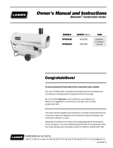
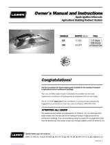
Fig. 1
LP Tank
First Stage Regulator (Tank Pressure Reduced to 5 psig)
Second Stage Regulator, 5 psig Inlet
Heater
GENERAL IINFORMATION
Pipe sizing is critical to the proper operation of any gas
heating system. However, piping is dependent on several
factors:
1. Total gas load expressed in BTUH.
2. The gas pressure to be supplied through the piping
system. This pressure may be expressed in pounds of
pressure per square inch (psi) or inches of water
column (W.C.).
3. Distance that the gas must travel to feed the heater
furthest from the regulator.
This section provides a basic explanation of how to size
piping for the heaters through the use of pipe sizing tables
and a
typical
example. In all cases with this example, we will
be using only pounds of pressure, expressed as 5 psi and not
inches of water column.
a. Black iron pipe only was used in this example as it is
less expensive per foot than copper tubing and,
therefore, more commonly used. However, the same
selection process using copper tubing may be done if
so desired. Refer to appropriate pipe sizing tables for
copper tubing. All pipe diameters given are measured
in inner diameter (I.D.). Piping planning and
installation must be done by an experienced, qualified
LP gas installation agency.
b. The minimum pipe size normally used in many
situations is 1/2 in. nominal.
c. The information in the pipe sizing tables was obtained
from Engineered Control International, Inc., L.P. Gas
Serviceman’s Manual L545.
d. Do not attempt gas supply line selection or installation
unless you are properly trained and qualified.
e. All gas supply lines must be leak checked after
installation and when pressurized to provide a safe
installation. Use only certified, approved leak
detectors.
f. This is one example showing how to size piping for a
building. Installation layouts differ as do the
pressures being supplied to piping, whether you are
using for LP gas or natural gas and the material (pipe
or copper tubing) being used.
INSTRUCTIONS
a.
Determine total gas demand for entire system, by
adding up BTUH input from heater dataplates and
adding demand for any other gas-fired appliances and
any future heaters.
b. Measure the length of piping required from outlet of
first-stage regulator to the appliance furthest away.
No other length is necessary to do the sizing. In this
example the distance from first-stage regulator to
appliance furthest away is 230 ft.
c. Make a sketch of the piping system and installation.
See Fig. 1.
Pipe Sizing
Installation
Instructions

2.2-22
Pipe Sizing
Installation
Instructions
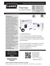
EXAMPLE
(Refer to Fig 2)
IMPORTANT:
If exact length is not on chart, use next longer
length. Select the size of pipe that shows at least as much
capacity as needed for each piping section.
a. Section A to B of pipe must supply the complete gas
load of 1,500,000 BTUH for the entire building.
Looking at the 5 PSIG sizing chart, the size of pipe
used in conveying gas would need to be sized at 1
inch diameter pipe. Note that even though furthest
distance from first stage regulator to appliance is 230
ft., we use the 250 ft. length.
b. Section B to C must supply the load of 1,000,000
BTUH. Select 3/4 inch pipe for Section B to C.
c. Section C to D must supply a load of 750,000 BTUH.
Select 3/4 inch pipe for Section C to D.
d. Section D to E must supply a load of 500,000 BTUH.
Select 1/2 inch pipe.
e. Sections E to F must supply 250,000 BTUH. Select
1/2 inch pipe.
f. Sections B to C must supply 500,000 BTUH. Use 1/2
inch pipe.
g. The final section, G to H, needs only 250,000 BTUH
for gas usage. This section would use 1/2 inch pipe.
Fig. 2
EXAMPLE
Perform pipe sizing for building.
Total heat load is 1,500,000 BTUH.
Quantity 6 - 250,000 BTUH heaters.
Building is 300 ft. long x 40 ft. wide.
Section BTUH LP Gas Pipe Size
Gas Load @ 5 PSIG
A - B 1,500,000 1 in.
B - C 1,000,000 3/4 in.
C - D 750,000 3/4 in.
D - E 500,000 1/2 in.
E - F 250,000 1/2 in.
B - G 500,000 1/2 in.
G - H 250,000 1/2 in.
First Stage Pipe Sizing
5 PSIG Inlet with a 1 PSIG Pressure Drop
Maximum capacity of pipe or tubing, in thousands of BTU/hr. of LP Gas
IMPORTANT: If exact length is not on chart, use next longer length. Select the size of pipe that shows at least as
much capacity as needed for each piping section.
Pipe Size Length of Pipe or Tubing
(In Inches) (In Feet)*
10 20 30 40 50 60 70 80 90 100
1/2 2946 2025 1626 1392 1233 1118 1028 957 897 848
3/4 6161 4234 3400 2910 2579 2337 2150 2000 1877 1773
1 11605 7976 6405 5482 4859 4402 4050 3768 3535 3339
125 150 175 200 225 250 275 300 350 400
1/2 751 681 626 583 547 516 490 468 430 400
3/4 1571 1424 1310 1218 1143 1080 1026 978 900 837
1 2956 2682 2467 2295 2153 2034 1932 1843 1696 1577
* Total length of piping from outlet of first stage regulator to inlet of second stage regulator (or to inlet of second
stage regulator furthest away).
August 1999

Tank Sizing
Installation
Instructions
ATTENTION
■ The following is supplied for informational purposes
only.
■ Consult your LP gas supplier for specific requirements.
A tank is propane storage container ranging in size from 150
gallons to 10,000 gallons or larger. For agricultural heating
applications, the tank sizes typically used are either 500
gallons or 1,000 gallons with 1,000 gallons being the most
common. The size and quantity of tanks will vary and is
dependent on the total heating load at the site.
In determining tank size and quantity, several factors apply:
■ Total heat load of the building
--- To determine total load, add up the heat input
(expressed in BTUH) for all gas-fired heaters,
pressure washers, water heaters, etc., that will be
drawing vapor from the tanks.
--- The heat input rating is located on the dataplate.
■ The coldest outside air temperature at night that the
tank(s) will be exposed to.
■ Percentage of propane remaining in the tank prior to
refill. Your fuel gas supplier will inform you at what
level a refill will normally occur.
IMPORTANT
■ Minimum vaporization of propane from liquid to vapor
occurs when temperatures are coldest and liquid level
of propane in the tank is lowest.
■ Size the quantity of tanks for the lowest temperature
you can expect in your area.
Refer to the following table to identify the heat output of
tanks at various temperatures and levels of fullness.
EXAMPLE
--- Select 1,000 gallon tank.
--- Total heat load is 1,500,000 BTUH (6-AB250
Heaters).
--- Coldest nighttime temperature is -10º F.
--- Tanks to be refilled by LP gas supplier when liquid
propane level is 30%.
A. In the 1,000 gallon tank sizing chart, locate -10º F.
outside temperature.
B. Locate the column which identifies 30% of propane
remaining in the tank prior to refill.
C. The intersection of these two variables identifies the
heat input. In this example, a 1,000 gallon tank can
supply 276,500 BTUH. (See shaded area in table.)
D. To determine the total number of tanks required:
Total Heat Load of Building
Heat Output of 1,000 Gallon Tank
or
1,500,000 BTUH/Building
276,500 BTUH/Tanks
NOTE:
Always round up fractions or decimals. See example.
(Example: 5.4 tanks = 6 tanks). This will give you some extra
capacity especially in cold weather, in the event your LP gas
supplier cannot refill your tanks immediately.
= 5.4 Tanks
(6 Tanks)
August 1999
2.3-11
Tank Size Outside Percentage of Liquid Propane
(Gallons) Temps. Remaining Prior to Refill
(Heat Input Expressed in BTUH)
º F. 80% 70% 60% 50% 40% 30% 20% 10%
0 532,800 488,400 444,000 400,000 355,000 311,000 266,000 200,000
500 -5 399,600 366,300 333,000 300,000 262,500 233,250 199,500 150,000
-10 266,400 244,200 222,000 200,000 177,500 155,500 133,000 100,000
-15 132,200 122,100 111,000 100,000 88,750 77,750 66,500 50,000
0 949,000 870,100 791,000 712,000 633,000 553,000 474,000 356,000
1,000 -5 711,900 652,575 593,250 534,000 474,750 414,750 355,500 267,000
-10 474,600 435,050 395,500 356,000 316,500 276,500 237,000 178,000
-15 237,300 217,525 197,750 178,000 158,250 138,250 118,500 89,000
NOTE: For above table, multiply the results obtained by one of the following factors if nighttime temperatures will
not reach 0º
F. :
Temperature Multiplier
+5º F. 1.25
+10º F. 1.50
+15º F. 1.75
+20º F. 2.00

2.4-11
August 1999
Tank Location and Installation
Installation
Instructions
ATTENTION
■ The following is supplied for informational purposes
only.
■ Tank installation shall only be accomplished by a
qualified LP gas installation person.
■ State and local codes must be observed at all times.
■ In absence of state and local codes, follow
ANSI/NFPA58 Standard for Storage and Handling of
Liquefied Petroleum Gases.
Once the proper size of the LP gas supply tank(s) has been
determined, attention must now be given to the most
convenient, yet safe, location of the tanks on the customer’s
property.
Tanks should be placed in a location pleasing to the
customer that does not conflict with state or local
regulations or NFPA 58 (Storage and Handling of Liquefied
Petroleum Gases).
Generally, LP gas tanks should be placed in an accessible
location for filling, supported by concrete of appropriate size
and reinforcement, and located away from vehicular traffic.
Where the tank may be subjected to abrasive action or
physical damage due to vehicular traffic or other causes, it
must be placed not less than two feet below grade, or
otherwise protected against such physical damage.
Regardless of its size, attention must be paid to the tank
distance from building openings, external sources of ignition,
intakes to any outdoor mounted heaters, or mechanical
ventilation systems. Refer to NFPA58 and the following
illustration for the minimum distances that the LP gas tanks
must be placed from the building or other objects.
INLET / EXHAUST FANS
501-2,000
GALLON TANK
CAPACITY
125-500 GALLON
TANK CAPACITY
10' MIN
10' MIN
25' MIN
(SEE NOTE 2)
VENTILATION FANS
NEAREST LINE OF ADJOINING PROPERTY
WHICH MAY BE BUILT UPON
NOTE: 1. REGARDLESS OF SIZE, ALL TANKS FILLED ON SITE MUST BE LOCATED AT LEAST 10 FEET FROM
NEAREST SOURCE OF IGNITION (FANS, HEATERS, ETC.)
2. THIS DISTANCE MAY BE REDUCED TO NO LESS THAN 10' FOR A SINGLE CONTAINER OF 1200 GALLON
CAPACITY OR LESS, PROVIDED THAT THE CONTAINER IS AT LEAST 25' FROM ANY OTHER L.P. GAS
CONTAINER OF MORE THAN 125 GALLON CAPACITY.
3. DISTANCE FROM TANK TO BUILDING FOR TANKS OF 2,001-30,000 GALLON CAPACITY IS 50 FEET.
25' MIN

LP Gas Tank Manifolding
Installation
Instructions
2.5-11
August 1999
ATTENTION
■ The following is supplied for informational purposes
only.
■ Tank manifolding shall only be accomplished by a
qualified LP gas installation person.
■ Local and state codes must be observed at all times.
■ In absence of state and local codes, follow
ANSI/NFPA58 Standard for Storage and Handling of
Liquefied Petroleum Gases.
It has been a long-standing industry practice to manifold two
or more LP gas storage tanks together in order to increase
gas system vaporization capacity.
However, when tanks are manifolded together, never use a
first-stage regulator at each tank. If this is done, the total
required capacity for the installation may not be obtained. It
is almost impossible to set all regulators at the identical
pressure. Therefore, the regulator delivering the highest
outlet pressure will backpressure the other regulators, in
turn keeping them from operating. In effect, only one tank
would be supplying gas to the building. In this situation,
especially on large capacity installations, ignition failures
would occur due to poor gas volume and pressure.
To eliminate this problem, run high pressure piping from the
LP gas tanks into a common line, then install one first-stage
regulator that can handle the required capacity of the
installation. Refer to the following illustrations.
TO BUILDING'S
SECOND STAGE
REGULATOR(S)
1,000 GALLON
TANKS
FIRST STAGE
REGULATORS
(ONE FOR
EACH TANK)
INCORRECT INSTALLATION
CORRECT INSTALLATION
1,000 GALLON
TANKS
FIRST STAGE REGULATOR
TO BUILDING'S
SECOND STAGE
REGULATOR(S)

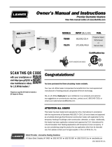
Manual Shut-Off Valve, Hose and Regulator Assembly
Installation
Instructions
1. Always use approved pipe thread compound suitable
for use with L.P. gas or natural gas on the threaded
connections.
2. Assemble the components together according to the
figure. This view is to show general assembly of the
components only.
3. Tighten all connections securely.
4.
Check aall cconnections ffor ggas lleaks uusing aapproved
gas lleak ddetectors.
5. The heater must have the proper gas regulator
installed for the application. A regulator must be
connected to the gas supply so that gas pressure at
the inlet to the gas valve is regulated within the range
specified on the dataplate at all times. Contact the
L.B. White Co., Inc. if you have any questions.
6. The heater’s gas regulator (with pressure relief valve)
should be installed outside of building. Any regulators
inside the buildings must be properly vented to the
outside. Local, state and national codes always apply
to regulator installation. Natural gas regulators with
vent limiting device may be mounted indoors without
venting to outdoors.
7. All gas pressure regulators must be installed in strict
accordance with the manufacturer’s safety
instructions. These instructions accompany each
regulator.
8. Any heater connected to a piping system must have an
accessible, approved manual shut off valve installed
within six feet (6 ft.) of the appliance it serves. The
manual shut-off valve can be installed before the
regulator, under the eave of the building, or after the
regulator inside the building.
August 1999
2.6-11
REGULATOR
NIPPLE
VALVE, MANUAL
SHUT-OFF
GAS HOSE
ADAPTER
SEDIMENT TRAP
TO CONTROL
VALVE INLET
REGULATOR VENT
GAS FLOW

2.7-11
August 1999
Sediment Trap
Installation
Instructions
Assemble the tee, nipples and cap together and tighten
securely. The sediment trap assembly must always be
mounted in a v
ertical position. Make sure pipe thread
compound that is resistant to both L.P. gas and natural gas
is used in making all connections.
Check aall cconnections ffor
gas lleaks uusing aapproved ggas lleak ddetectors.
Make certain that a sediment trap is installed at the gas
valve inlet to prevent foreign materials (pipe compound, pipe
chips and scale) from entering the gas valve. Debris blown
into the gas valve may cause a malfunction resulting in a
serious gas leak that could result in a possible fire or
explosion causing loss of products, building or even life. A
properly installed sediment trap will keep foreign materials
from entering the gas valve and protect the safe functioning
of that important safety component.
5 iin.
Nipple
Gas CControl
Valve IInlet
3 iin.
Nipple
Cap
Tee
/