Page is loading ...

Operator’s Manual
IMPORTANT: Read this manual carefully. It contains information about your
safety and the safety of others. Also become familiar with the controls and
their proper use before you operate the product.
FORM NO. 3323–395
Z–320
OUT FRONT Z
Model No. 74191 – 895001 & Up

The Toro Company – 1999
All Rights Reserved
Introduction
Thank you for purchasing a Toro product.
All of us at Toro want you to be completely satisfied
with your new product, so feel free to contact your
local Authorized Service Dealer for help with service,
genuine replacement parts, or other information you
may require.
Whenever you contact your Authorized Service
Dealer or the factory, always know the model and
serial numbers of your product. These numbers will
help the Service Dealer or Service Representative
provide exact information about your specific
product. You will find the model and serial number
plate located in a unique place on the product as
shown below.
1
1. Model and Serial Number Plate
For your convenience, write the product model and
serial numbers in the space below.
Model No:
Serial No.
Read this manual carefully to learn how to operate
and maintain your product correctly. Reading this
manual will help you and others avoid personal injury
and damage to the product. Although we design,
produce and market safe, state-of-the-art products,
you are responsible for using the product properly
and safely. You are also responsible for training
persons, who you allow to use the product, about safe
operation.
The warning system in this manual identifies
potential hazards and has special safety messages that
help you and others avoid personal injury, even death.
DANGER, WARNING and CAUTION are signal
words used to identify the level of hazard. However,
regardless of the hazard, be extremely careful.
DANGER signals an extreme hazard that will cause
serious injury or death if the recommended
precautions are not followed.
WARNING signals a hazard that may cause serious
injury or death if the recommended precautions are
not followed.
CAUTION signals a hazard that may cause minor or
moderate injury if the recommended precautions are
not followed.
Two other words are also used to highlight
information. “Important” calls attention to special
mechanical information and “Note” emphasizes
general information worthy of special attention.
The left and right side of the machine is determined
from the normal operator’s position.
The engine exhaust from this product
contains chemicals known to the State of
California to cause cancer, birth defects,
or other reproductive harm.
IMPORTANT: This engine is not equipped
with a spark arrester muffler. It is a violation
of California Public Resource Code Section
4442 to use or operate this engine on any
forest–covered, brush–covered or
grass–covered land. Other states or federal
areas may have similar laws.

1
Contents
Page
Safety 3. . . . . . . . . . . . . . . . . . . . . . . . . . . . . . . . .
Gasoline and Oil 11. . . . . . . . . . . . . . . . . . . . . . . .
Recommended Gasoline 11. . . . . . . . . . . . . . .
Stabilizer/Conditioner 12. . . . . . . . . . . . . . . .
Filling the Fuel Tank 12. . . . . . . . . . . . . . . . .
Check Engine Oil Level 12. . . . . . . . . . . . . . .
Assembly 13. . . . . . . . . . . . . . . . . . . . . . . . . . . . . .
Loose Parts 13. . . . . . . . . . . . . . . . . . . . . . . . .
Install Castor Wheel 14. . . . . . . . . . . . . . . . . .
Check Tire Pressure 14. . . . . . . . . . . . . . . . . .
Secure PTO Cover 14. . . . . . . . . . . . . . . . . . .
Activate the Battery 15. . . . . . . . . . . . . . . . . .
Install Battery 16. . . . . . . . . . . . . . . . . . . . . . .
Install Recycler Baffles 17. . . . . . . . . . . . . .
Recycler Operation 17. . . . . . . . . . . . . . . . .
Install Bagger and Discharge Baffles 18. . . . .
Bagger Operation 18. . . . . . . . . . . . . . . . . . . .
Operation 19. . . . . . . . . . . . . . . . . . . . . . . . . . . . . .
Think Safety First 19. . . . . . . . . . . . . . . . . . .
Controls 19. . . . . . . . . . . . . . . . . . . . . . . . . . .
Parking Brake 20. . . . . . . . . . . . . . . . . . . . . . .
Starting and Stopping Engine 21. . . . . . . . . .
Operating Power Take Off (PTO) 22. . . . . . .
The Safety Interlock System 23. . . . . . . . . . .
Instruments 23. . . . . . . . . . . . . . . . . . . . . . . . .
Driving Forward or Backward 24. . . . . . . . . .
Stopping the Machine 25. . . . . . . . . . . . . . . .
Positioning the Seat 25. . . . . . . . . . . . . . . . . .
Adjusting Height-of-Cut 26. . . . . . . . . . . . . .
Adjusting Rollers 26. . . . . . . . . . . . . . . . . . . .
Tilting the Mower 27. . . . . . . . . . . . . . . . . . .
Dumping the Hopper 28. . . . . . . . . . . . . . . . .
Pushing the Machine by Hand 29. . . . . . . . . .
Page
Maintenance 30. . . . . . . . . . . . . . . . . . . . . . . . . . . .
Service Interval Chart 30. . . . . . . . . . . . . . . .
Air Cleaner 31. . . . . . . . . . . . . . . . . . . . . . . . .
Engine Oil 33. . . . . . . . . . . . . . . . . . . . . . . . .
Spark Plug 35. . . . . . . . . . . . . . . . . . . . . . . . .
Greasing and Lubrication 36. . . . . . . . . . . . . .
Gearbox Fluid 37. . . . . . . . . . . . . . . . . . . . . .
Changing Gearbox Fluid 37. . . . . . . . . . . . . .
Checking Gearbox Fluid 38. . . . . . . . . . . . . .
Replacing the Castor Wheel Fork Bushings 38
Servicing the Castor Wheels and Bearings 39
Replacing Push Arm Bushings 40. . . . . . . . .
Cleaning the Cooling Systems 41. . . . . . . . . .
Tire Pressure 42. . . . . . . . . . . . . . . . . . . . . . . .
Fuel Filter 42. . . . . . . . . . . . . . . . . . . . . . . . . .
Fuel Tank 43. . . . . . . . . . . . . . . . . . . . . . . . . .
Hydraulic System 43. . . . . . . . . . . . . . . . . . . .
Adjust Motion Controls 45. . . . . . . . . . . . . . .
Adjust Mowing Speed Reference Position 46
Replacing Power Take Off (PTO) Belts 47. . .
Replacing the Traction Belt 48. . . . . . . . . . . .
Replacing the Blower Belt 49. . . . . . . . . . . . .
Fuse 49. . . . . . . . . . . . . . . . . . . . . . . . . . . . . .
Battery 50. . . . . . . . . . . . . . . . . . . . . . . . . . . .
Cleaning Hopper Screens 51. . . . . . . . . . . . . .
Cleaning the Hopper Full Sensor 51. . . . . . . .
Cutting Blades 52. . . . . . . . . . . . . . . . . . . . . .
Correcting Cutting Unit Mismatch 55. . . . . .
Setting the Front-to-Rear Pitch 55. . . . . . . . .
Setting the Side-to-Side Leveling 56. . . . . . .
Wiring Diagram 57. . . . . . . . . . . . . . . . . . . . .
Hydraulic Diagram 58. . . . . . . . . . . . . . . . . . .
Cleaning and Storage 59. . . . . . . . . . . . . . . . .
Troubleshooting 60. . . . . . . . . . . . . . . . . . . . . . . . .

Contents
2
The enclosed Engine Owner’s Manual is supplied for information
regarding The U.S. Environmental Protection Agency (EPA) and
the California Emission Control Regulation of emission systems,
maintenance and warranty.
Keep this engine Owner’s Manual with your unit. Should this
engine Owner’s Manual become damaged or illegible, replace
immediately. Replacements may be ordered through the engine
manufacturer.

3
Safety
Safe Operation Practices for
Ride-on (riding) Rotary
Lawnmower Machines
Training
1. Read the instructions carefully. Be familiar with
the controls and the proper use of the equipment.
2. Never allow children or people unfamiliar with
these instructions to use the lawnmower. Local
regulations may restrict the age of the operator.
3. Never mow while people, especially children, or
pets are nearby.
4. Keep in mind that the operator or user is
responsible for accidents or hazards occurring to
other people or their property.
5. Do not carry passengers.
6. All drivers should seek and obtain professional
and practical instruction. Such instruction should
emphasize:
• the need for care and concentration when
working with ride-on machines;
• control of a ride-on machine sliding on a
slope will not be regained by the application
of the brake. The main reasons for loss of
control are:
insufficient wheel grip;
being driven too fast;
inadequate braking;
the type of machine is unsuitable for its
task;
lack of awareness of the effects of
ground conditions, especially slopes;
incorrect hitching and load distribution.
Preparation
1. While mowing, always wear substantial
footwear and long trousers. Do not operate the
equipment when barefoot or wearing open
sandals.
2. Thoroughly inspect the area where the
equipment is to be used and remove all objects
which may be thrown by the machine.
3. WARNING – Petrol is highly flammable.
• Store fuel in containers specifically
designed for this purpose.
• Refuel outdoors only and do not smoke
while refuelling.
• Add fuel before starting the engine. Never
remove the cap of the fuel tank or add
petrol while the engine is running or when
the engine is hot.
• If petrol is spilled, do not attempt to start
the engine but move the machine away
from the are of spillage and avoid creating
any source of ignition until petrol vapors
have dissipated.
• Replace all fuel tanks and container caps
securely.
4. Replace faulty silencers.
5. Before using, always visually inspect to see that
the blades, blade bolts and cutter assembly are
not worn or damaged. Replace worn or damaged
blades and bolts in sets to preserve balance.
6. On multi–bladed machines, take care as rotating
one blade can cause other blades to rotate.

Safety
4
Operation
1. Do not operate the engine in a confined space
where dangerous carbon monoxide fumes can
collect.
2. Mow only in daylight or in good artificial light.
3. Before attempting to start the engine, disengage
all blade attachment clutches and shift into
neutral.
4. Do not use on slopes of more than:
• Never mow side hills over 5
• Never mow uphill over 10
• Never mow downhill over 15
Note: Slope angle is calculated as in
5.4.2.3.2.
5. Remember there is no such thing as a “safe”
slope. Travel on grass slopes requires particular
care. To guard against overturning:
• do not stop or start suddenly when going up
or downhill;
• engage clutch slowly, always keep machine
in gear, especially when travelling
downhill;
• machine speeds should be kept low on
slopes and during tight turns;
• stay alert for bumps and hollows and other
hidden hazards;
• never mow across the face of the slope,
unless the lawnmower is designed for this
purpose.
6. Use care when pulling loads or using heavy
equipment.
• Use only approved drawbar hitch points.
• Limit loads to those you can safely control.
• Do not turn sharply. Use care when
reversing.
• Use counterweight(s) or wheel weights
when suggested in the instruction
handbook.
7. Watch out for traffic when crossing or near
roadways.
8. Stop the blades rotating before crossing surfaces
other than grass.
9. When using any attachments, never direct
discharge of material toward bystanders nor
allow anyone near the machine while in
operation.
10. Never operate the lawnmower with defective
guards, shields or without safety protective
devices in place.
11. Do not change the engine governor settings or
overspeed the engine. Operating the engine at
excessive speeds may increase the hazard of
personal injury.
12. Before leaving the operator’s position:
• disengage the power take-off and lower the
attachments;
• change into neutral and set the parking
brake;
• stop the engine and remove the key.
13. Disengage drive to attachments, stop the engine,
and disconnect the spark plug wire(s) or remove
the ignition key
• before cleaning blockages or unclogging
chute;
• before checking, cleaning or working on the
lawnmower;
• after striking a foreign object. Inspect the
lawnmower for damage and make repairs
before restarting and operating the
equipment;
• if the machine starts to vibrate abnormally
(check immediately).
14. Disengage drive to attachments when
transporting or not in use.

Safety
5
15. Stop the engine and disengage drive to
attachment
• before refuelling;
• before removing the grass catcher;
• before making height adjustment unless
adjustment can be made from the operator’s
position.
16. Reduce the throttle setting during engine run-out
and, if the engine is provided with a shut-off
valve, turn the fuel off at the conclusion of
mowing.
Maintenance and storage
1. Keep all nuts, bolts and screws tight to be sure
the equipment is in safe working condition.
2. Never store the equipment with petrol in the tank
inside a building where fumes may reach an
open flame or spark.
3. Allow the engine to cool before storing in any
enclosure.
4. To reduce the fire hazard, keep the engine,
silencer, battery compartment and petrol storage
area free of grass, leaves, or excessive grease.
5. Check the grass catcher frequently for wear or
deterioration.
6. Replace worn or damaged parts for safety.
7. If the fuel tank has to be drained, this should be
done outdoors.
8. On multi-bladed machines, take care as rotating
one blade can cause other blades to rotate.
9. When machine is to be parked, stored or left
unattended, lower the cutting means unless a
positive mechanical lock is used.
Sound Pressure
This unit has an equivalent continuos A-weighted
sound pressure at the operator ear of: 90 dB(A), based
on measurements of identical machines per
81/1051/EEC.
Sound Power
This unit has a power level of: 105 dB(A)/1pW, based
on measurements of identical machines per Directive
84/539/EEC.
Vibration Level
This unit has a maximum hand-arm vibration level of
XX m/s
2
, and whole body vibration level of XX m/s
2
,
based on measurements of identical machines per EN
1032 and EN 1033.

Safety
6
Slope Chart
Read all safety instructions on pages 3–10.

Safety
7

Safety
8
Symbols Glossary
Safety alert triangle–
Read operator’s manual
Caustic liquids, chemical
burns to fingers or hand
First aid, flush with water
Fire, open light & smoking
prohibited
Eye protection must
be worn
Caution, toxic risk
Shut off engine & remove
key before preforming
Safety alert symbol
symbol within triangle
indicates a hazard
Consult technical manual
for proper service procedures
maintenance or repair work
Fire or open flame
Explosion
Do not dispose of lead
battery in garbage
Stay a safe distance
from the machine
Keep children a safe
distance from machine
Stay safe distance
from machine, out front Z
Keep children away
from battery
Stay a safe distance
from the machine
Hearing protection must
be worn

Safety
9
Symbols Glossary
Finger & hand engagement,
Severing of toes & fingers,
Thrown or flying objects,
Do not open or
remove safety shields
while engine is running
Blade retaining bolts must be
Torqued to 115–149 N.m
Hand & arm engagement,
rotary mower blade
whole body exposure
Thrown or flying objects,
whole body exposure
Keep guards and safety
sheilds in place
Severing of fingers or
hand-engine fan
Dismemberment, rider backing
Do not carry passengers
Hot surface, burns to
fingers or hands
Blade cutting element-
height adjustment
(mm)
Machine rollover,
Machine rollover, do not
Out Front Z
use on side hill slope
greater than 5 degrees
Dismemberment, Out Front Z
Stored energy hazard,
kickback or upward motion
Machine rollover, do not
use on down hill slope
greater than 10 degrees
Machine rollover, do not
use on up hill slope
greater than 15 degrees
belt drive
belt drive
in forward motion
Whole body entanglement,
implement input drive line

Safety
10
Symbols Glossary
Fast
Slow
Decreasing/Increasing
Engine start
Engine stop
Choke
Oil Lubrication Point
Power take off (PTO)
Alarm
Engage
Disengage
Brake system
Parking brake
On/Run
Battery
Off/stop
Elapsed Operating Hours
Engine run

11
Gasoline and Oil
Recommended Gasoline
Use UNLEADED Regular Gasoline suitable for
automotive use (85 pump octane minimum). Leaded
regular gasoline may be used if unleaded regular is
not available.
IMPORTANT: Never use methanol, gasoline
containing methanol, or gasohol containing
more than 10% ethanol because the fuel
system could be damaged. Do not mix oil with
gasoline.
POTENTIAL HAZARD
• In certain conditions gasoline is extremely
flammable and highly explosive.
WHAT CAN HAPPEN
• A fire or explosion from gasoline can burn
you, others, and cause property damage.
HOW TO AVOID THE HAZARD
• Use a funnel and fill the fuel tank outdoors,
in an open area, when the engine is cold.
Wipe up any gasoline that spills.
• Do not fill the fuel tank completely full.
Add gasoline to the fuel tank until the level
is 1/4” to 1/2” (6 mm to 13 mm) below the
bottom of the filler neck. This empty space
in the tank allows gasoline to expand.
• Never smoke when handling gasoline, and
stay away from an open flame or where
gasoline fumes may be ignited by a spark.
• Store gasoline in an approved container
and keep it out of the reach of children.
Never buy more than a 30-day supply of
gasoline.
POTENTIAL HAZARD
• When fueling, under certain circumstances,
a static charge can develop, igniting the
gasoline.
WHAT CAN HAPPEN
• A fire or explosion from gasoline can burn
you and others and cause property damage.
HOW TO AVOID THE HAZARD
• Always place gasoline containers on the
ground away from your vehicle before
filling.
• Do not fill gasoline containers inside a
vehicle or on a truck or trailer bed because
interior carpets or plastic truck bed liners
may insulate the container and slow the
loss of any static charge.
• When practical, remove gas–powered
equipment from the truck or trailer and
refuel the equipment with its wheels on the
ground.
• If this is not possible, then refuel such
equipment on a truck or trailer from a
portable container, rather than from a
gasoline dispenser nozzle.
• If a gasoline dispenser nozzle must be used,
keep the nozzle in contact with the rim of
the fuel tank or container opening at all
times until fueling is complete.

Gasoline and Oil
12
Stabilizer/Conditioner
Add the correct amount of gas stabilizer/conditioner
to the gas. Using a stabilizer/conditioner in the
machine:
• Keeps gasoline fresh during storage of 90 days
or less. For longer storage it is recommended
that the fuel tank be drained.
• Cleans the engine while it runs
• Eliminates gum-like buildup in the fuel system,
which causes hard starting
IMPORTANT: Never use fuel additives
containing methanol or ethanol.
Filling the Fuel Tank
1. Shut the engine off and set the parking brake.
2. Clean around the fuel tank cap and remove the
cap. Add unleaded regular gasoline until the
level is to the bottom of the filler neck. Do not
fill the neck completely full, this space in the
tank allows gasoline to expand.
3. Install fuel tank cap securely. Wipe up any
gasoline that may have spilled.
Check Engine Oil Level
Before you start the engine and use the machine,
check the oil level in the engine crankcase; refer to
Checking Oil Level, page 33.

13
Assembly
Loose Parts
Note: Use the chart below to verify all parts have been shipped.
DESCRIPTION QTY. USE
Wheel assembly–castor
Bolt 1/2–13 x 9” (228 mm)
Locknut 1/2–13
Washer 1/2” (13 mm)
Spacer
1
1
1
2
1
Install castor wheel
Battery
Battery clamp
Battery support rod
Wing nut 1/4–20
Terminal boot
Bolt 1/4–20 x 3/4” (19 mm)
Washer 1/4”
1
1
2
4
1
2
2
Install battery
Shoulder bolt
Locknut
1
1
Secure power take off (PTO) cover
Recycler
baffle – left
Recycler
baffle – right
Carriage bolt 5/16–18 x 3/4” (19 mm)
Locknut 5/16”
1
1
6
6
Install Recycler
baffles
Key
Safety Booklet
Operator’s Manual
Engine Operator’s Manual
Parts Catalog
Registration card
2
1
1
1
1
1
Read before operating machine
For ordering parts
Fill out and return to Toro

Assembly
14
Install Castor Wheel
1. Remove nut, washers, spacer and axle shaft from
fork (Fig. 1).
2. Jack up rear of unit and install rear wheel into
castor fork (Fig. 1).
3. Place wheel with spacer installed and washers
between fork and slide bolt through bearings
(Fig. 1).
4. Secure bolt with 1/2” locknut (Fig. 1).
5. Torque nut to 75 ft–lb (55 N⋅m).
6. Grease castor wheel bearings (Fig. 1).
m–3227
Figure 1
1. Wheel assembly
2. Bolt 1/2–13 x 9” (227 mm)
3. Washer 1/2” (13 mm)
4. Spacer
5. Locknut 1/2”
Check Tire Pressure
Check the air pressure in all tires: refer to Tire
Pressure in Maintenance section on page 42.
Secure PTO Cover
To lower mower refer to: Tilting the Mower in
Operation section on page 27.

Assembly
15
Activate the Battery
Bulk electrolyte with 1.260 specific gravity must be
purchased from a local battery supply outlet.
1. Remove the battery from the machine.
IMPORTANT: Be careful not to damage the
long vent tube when removing the battery
box.
POTENTIAL HAZARD
• Battery electrolyte contains sulfuric acid
which is a deadly poison and it causes
severe burns.
WHAT CAN HAPPEN
• If you carelessly drink electrolyte you could
die or if it gets onto your skin you will be
burned.
HOW TO AVOID THE HAZARD
• Do not drink electrolyte and avoid contact
with skin, eyes or clothing. Wear safety
glasses to shield your eyes and rubber
gloves to protect your hands.
• Fill the battery where clean water is always
available for flushing the skin.
• Follow all instructions and comply with all
safety messages on the electrolyte container.
2. Remove filler caps from the battery. Slowly pour
electrolyte into each cell until the electrolyte
level is up to the lower part of the tube (Fig. 2).
1
2
3
m–1262
Figure 2
1. Filler caps
2. Electrolyte
3. Lower part of the tube

Assembly
16
3. Leave the covers off and connect a 3 to 4 amp
battery charger to the battery posts (Fig. 3).
Charge the battery at a rate of 4 amperes or less
for 4 hours (12 volts).
4
1
2
3
m–1254
Figure 3
1. Positive post
2. Negative post
3. Charger red (+) wire
4. Charger black (–) wire
POTENTIAL HAZARD
• Charging battery produces gasses.
WHAT CAN HAPPEN
• Battery gasses can explode.
HOW TO AVOID THE HAZARD
• Keep cigarettes, sparks and flames away
from battery.
4. When the battery is fully charged, disconnect the
charger from the electrical outlet then from the
negative and positive battery posts (Fig. 3).
5. Slowly pour electrolyte into each cell until the
level is once again up to the “UPPER” line on
the battery case (Fig. 2) and install covers.
Install Battery
1. Fill battery with electrolyte and charge, refer to
BATTERY, page 50.
2. Position battery in tray with terminal posts
toward the engine (Fig. 4).
3. Slide the red terminal boot onto the red battery
cable.
4. Install the positive (red) battery cable to positive
(+) battery terminal then negative battery cable
to the negative (–) battery terminal. Secure
cables with (2) 1/4 x 3/4” (19 mm) bolts 1/4”
washers, 1/4” lock washers and 1/4” locknuts.
IMPORTANT: Route cables so they do not
contact metal edges or frame members.
5. Secure battery with (2) support rods, a battery
clamp and (2) 1/4” wing nuts. Position support
rods in mounting holes (Fig. 4). Tighten wing
nuts so battery is held securely in position and
will not slide. DO NOT OVERTIGHTEN.
1
m–3224
2
5
9
3
4
9
6
7
8
Figure 4
1. Battery tray
2. Terminal boot
3. Positive battery cable
4. Negative battery cable
5. Bolt 1/4–20 x 3/4” (19 mm)
6. Washer 1/4”
7. Battery support rod
8. Battery clamp
9. Wing nut 1/4”

Assembly
17
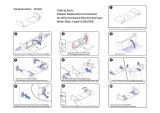
Install Recycler
Baffles
1. Tilt mower into the vertical position, refer to;
Tilting the Mower, page 27.
2. Remove cap screws, left and right bagger baffles
locknuts, carriage bolts, and left and right
discharge baffles from the mower (Fig. 7).
Note: Save all hardware for use when
installing bagger.
3. Locate the left and right Recycler
baffles inside
mower and secure with (6) 1/4–20 x 3/4”
(19 mm) cap screws, through from the bottom of
mower, washers, (4) 1/4”–20 retained nuts and
1/4–20 locknuts (Fig. 5).
1
2
3
4
Figure 5
1. Recycler
baffle
2. Cap Screw
3. Retainer Nut
4. Washer (.344x.688)
Recycler
Operation
When operating the mower with Recycler
baffles
installed you must disengage the blower drive belt.
1. Stop the engine, remove the key and disconnect
the spark plug wire(s) from the spark plug(s).
2. Remove hairpin cotter and clevis pin from idler
arm (Fig. 6).
3. Push up on the spring loaded idler arm, behind
PTO (power take off) gearbox, to relax pressure
on blower belt (Fig. 6).
4. Align hole in idler arm with slot in frame and
insert clevis pin. Secure with hairpin cotter to
hold in position.
1
2
3
4
Figure 6
1. Idler arm
2. Frame slot
3. Clevis pin
4. Hairpin cotter

Assembly
18
Install Bagger and Discharge
Baffles
When changing between bagging and recycling,
baffles must be removed and replaced
1. Tilt mower into the vertical position, refer to;
Tilting the Mower, page 27.
2. Remove capscrews ,locknuts, carriage bolts and
Recycler
baffles from the mower (Fig. 5).
Note: Save all hardware for use when
installing Recycler
baffles.
3. Locate the left and right bagger baffles inside the
mower and secure with (6) 5/16–18 x 3/4”
(19 mm) carriage bolts, through from the top of
mower, and (6) 5/16” locknuts (Fig. 7).
4. Locate the left and right discharge baffles inside
the mower and secure with (4) 5/16–18 x 3/4”
(19 mm) carriage bolts, through from the bottom
and inside of mower, washers, and (4) 5/16”
locknut.(Fig. 7).
1
3
6
5
2
4
3
Figure 7
1. Bagger baffle
2. Retainer Nut
3. Cap Screw
4. Discharge baffle
5. Washer (.344x.688)
6. Carriage Bolt
Bagger Operation
When operating the mower with bagger baffles
installed you must engage the blower drive belt.
1. Stop the engine, remove the key and disconnect
the spark plug wire(s) from the spark plug(s).
2. Place belt around blower, idler and PTO pulleys.
3. Push up on the spring loaded idler arm, behind
PTO (power take off) gearbox, to relax pressure
on spring (Fig. 6).
4. Remove hairpin cotter and clevis pin from slot in
frame and allow idler to tension belt (Fig. 6).
5. Install hairpin cotter and clevis pin in outer hole
of idler arm for storage (Fig. 6).
1
2
3
4
Figure 8
1. Idler arm
2. Frame slot
3. Clevis pin
4. Hairpin cotter
/