Page is loading ...

RAYNOR GARAGE DOORS DIXON , ILLINOIS 61021
IMPORTANT:
ControlHoist Standard
Industrial Duty
BELT DRIVE
Trolley
INSTALLATION INSTRUCTIONS
AND
USER GUIDE
-NOT FOR RESIDENTIAL USE-
-FOR INDOOR USE ONLY-
STANDARD
SAVE THESE INSTRUCTIONS
INSTALLER: ATTACH THIS BOOKLET TO WALL NEXT
TO PUSH BUTTON.
Model CST
ControlHoist 2.0
PLEASE READ THESE INSTRUCTIONS BEFORE STARTING INSTALLATION. IT IS
IMPORTANT THAT THIS OPERATOR BE INSTALLED CORRECTLY IN ORDER TO
ACHIEVE SAFE AND PROPER OPERATION.
THIS OPERATOR HAS BEEN SUPPLIED FROM THE FACTORY WITH CONSTANT
PRESSURE TO CLOSE. IF OTHER WIRING TYPES ARE REQUIRED, A PHOTO ELECTRIC
CONTROL MODEL OSE-S5000 BY VITECTOR FRABA, MODEL HAE00056 BY LINEAR
CORP, OR MILLER ELECTRIC REVERSING EDGE MODEL ME WITH BLUE COLOR BAND
IS REQUIRED.
Rev. 06/15
5973129-1

LIMITED WARRANTY
SPECIFICATIONS
The Raynor ControlHoist Standard Trolley type electric operator is designed for use on commercial and industrial size sectional
overhead doors only.
HEADROOM REQUIREMENT
BACKROOM REQUIREMENT
CONTROL
DOOR TYPE
ADJUSTABLE FRICTION CLUTCH
REDUCTION
OVERLOAD PROTECTION
DOOR TRAVEL
LIMIT SWITCHES
A minimum of 4 inches is required above high point of
door travel.
Opening height plus 4'-6" clearance back from header
(plus 5'-6" on low headroom).
24 volt secondary control circuit as standard.
For use on normal and low headroom sectional overhead
garage doors.
Provided to protect door and operator if door movement
is obstructed.
V-belt drive from motor to full ball bearing power train
with additional chain and sprocket redution.
Manual reset type for over current protection.
Operator to move door 8 to 12 inches per second.
Chain drive, screw type.
5973129-2
Page 2
Raynor warrants the electrical operator and component parts for two (2) years against defects in material and workmanship.
Under the terms of this limited warranty, for any operator components that are found to be defective upon inspection by
authorized Raynor personnel, Raynor will, at its option, repair or replace the defective door components. Labor charges for
installations or repairs shall be the responsibility of the consumer and must be performed by an authorized Raynor Dealer.
This warranty extends only to the original purchaser. This warranty is not transferable.
Raynor shall not be liable for any consequential or incidental damages.
Some states do not allow the exclusion or limitation of consequential or incidental damages, so the above limitation or
exclusion may not apply to you.
Claims for defects in material and workmanship covered by this warranty shall be made in writing with proof of purchase
to the dealer from whom the product was purchased or call Raynor at 1-800-4
-RAYNOR within the warranty period. Raynor
may choose to have the product returned for inspection.
This warranty gives you specific legal rights. You may also have other rights, which may vary from state to state.
This warranty applies only to doors that are professionally installed by an authorized Raynor Dealer.
This warranty does not apply to any damage or deterioration caused by abuse or failure to provide reasonable and
necessary maintenance.
ALL OTHER WARRANTIES, EXPRESS OR IMPLIED, INCLUDING ANY WARRANTY OF MERCHANTABILITY,
ARE HEREBY EXPRESSLY EXCLUDED.
MOTOR
FREQUENCY OF OPERATION
Continuous duty rated, 1725 RPM.
Will handle up to 30 cycles per hour or 300 cycles per
day.

IMPORTANT INSTALLATION INSTRUCTIONS
WARNING - Failure to follow these precautions
may result in severe personal injury or death.
5973129-3
Page 3
1) READ AND FOLLOW ALL INSTALLATION INSTRUCTIONS.
2) Door must be properly balanced and free working before installing the operator. Improperly
balanced door can be hazardous and cause severe injury. Repairs to cables, spring
assemblies and other hardware must be made by qualified door installer.
Operator damage may result if installed on an improperly working door. Safety features of
operator will not function properly if door is out of balance.
3) Do not connect to electric power until installation is completed.
4) Remove or make inoperative any locking device unless operator is equipped with door lock
interlock feature.
5) Remove all ropes, step plates and lift handles connected to the door before operating the
garage door operator.
6) Installation and wiring must conform to local building and electrical codes.
7) Do not operate the transmitter or wall push-button unless the door is in sight.
8) Do not allow children to play with or in the area of the door and controls.
9) Do not place hands in area of pulleys, V-belt, sprockets, chain or rotating shafts.
10) Install warning placard on wall next to push-button.
11) Attach instruction booklet to wall near push-button.
12) Do not attempt to make electrical repairs without shutting off power to the unit.
13) Traffic patterns (vehicular and personnel) should be evaluated and proper safety equipment
or push-button wiring installed to prevent damage or injuries.
14) Clutch should be adjusted according to procedure outlined on page 7 and checked
periodically
15) Garage doors should
NEVER be used as pedestrian doors.
16) Install the door operator at least 8 ft (2.44 m) or more above the floor. If the operator must be
mounted less than 8 ft (2.44m) above the floor, the exposed moving parts must be protected
by covers or guarding. Contact the manufacturer.
17) Verify that all labels for door and operator are in place, see page 16 for proper placement.
18) Install the Entrapment Warning Placard next to control station in a prominent location.
19) Locate the control station: (a) within sight of the door, (b) at a minimum height of 5 feet so
small children cannot reach it, and (c) away from all moving parts of the door or operator.
20) For products having a manual release, instruct the end user on the proper operation of the
manual release.

door arm, fasteners and miscellaneous parts. The rail assembly includes the roller chain.
Bolt powerhead to rail assembly using 5/16 x 3/4 flat-hd
ASSEMBLE CHAIN Fig. 3
the power source available and compare it with the
PRELIMINARY INSPECTION
This operator as shipped contains one carton and a rail assembly. The carton contains the powerhead, trolley carriage,
and within 6" of front mounting bracket.
ASSEMBLY INSTRUCTIONS
Visually inspect all parts of the operator for shipping
Tighten all bolts securely.
that the correct operator was shipped to you. Also check
Slide trolley carriage (A), Fig. 1, all the way forward on the
items:
certain that all loose parts are removed before discard-
damage.
bolts and whiz lock nuts furnished in hardware package.
Before proceeding with the installation of your Raynor Trolley Operator, it is advisable that you check the following
Page 4
RAIL AND CARRIAGE ASSEMBLY
Check the nameplate located on the powerhead to verify
Check shipping container for damage. Notify delivering
VISUAL INSPECTION
carrier immediately.
rail assembly with lug (B) facing the open end of the rails
ing packing material.
Unpack powerhead and trolley rail assemblies being
5973129-4
electrical data on the nameplate.
ATTACH POWERHEAD Fig.2
PACKAGING
Apply 3/8" hex nut furnished in hardware package to
adjustment rod (C) and install chain around front idler
sprocket at front of rail assembly and feed under trolley
rail brackets to drive sprocket on powerhead. Feed
adjustment rod around drive sprocket then back to trolley
carriage. Install lock washer and feed through lug (B) of
carriage just far enough to start second nut. Thread other
end of chain through chain keeper (E) as shown.
Warning! Improper lead in of chain could cause
damage to door, operator or personnel.
Take up slack in chain and tighten cap screw (D). Make
final adjustments of chain tension by adjusting nuts on
rod (C).
FRONT MOUNTING BRACKET
TROLLEY CARRIAGE (A)
LUG (B)
FIG. 1
RAIL ASSEMBLY
POWERHEAD
5/16" x 3/4" FLAT HEAD BOLTS
& WHIZ LOCK NUTS
5/16" x 3/4" FLAT HEAD BOLTS
& WHIZ LOCK NUTS
CHAIN KEEPER (E)CHAIN KEEPER (E)
5/16" x 1" CAP SCREW (D)
LUG (B)
3/8" HEX NUT3/8" HEX NUT
LOCK WASHER
ADJUSTING
ROD (C)
TROLLEY CARRIAGE (A)
FIG. 3
FIG. 2

INSTALLATION INSTRUCTIONS
Page 5
5973129-5
FIG. 5
FIG. 6
Many of the problems related to electric operators are due to improper installation. The following
installation procedures are recommended to minimize these problems.
INSTALL FRONT MOUNTING BRACKET
Begin installation with door in closed position.
Measure width of door to find exact center and mark
centerline on header. Extend centerline above spring
assembly.
Locate high rise point of door, Fig. 4, and use level to
mark high point on header as shown.
Remove front mounting bracket (See Fig. 1) from rail
assembly and install on front wall above spring
assembly, Fig. 5. If headroom permits, bottom edge
of bracket should be 2 inches above high rise point
marked on header. Secure bracket to wall using either
lag screws or self tapping screws furnished in
hardware package.
HANGING OPERATOR Fig. 6
Resting powerhead of operator on floor, attach front end
of rails to front mounting bracket. Swing unit into position
over door and temporarily hang powerhead end with
strong rope or place on tall ladder. Rear of operator
should be as low as possible and still allow door to clear
rail assembly.
Note: If rear of operator is mounted too
high, permanent damage to door could result.
With operator in desired position, cut angle iron hangers
and secure operator at rear.
Caution: Raynor recommends a center support
hanger on all installations over 10 feet high.
With hangers in place, tighten all bracket bolts. Remove
temporary hanger or ladder.
Warning: Be certain mounting bracket is level
and mounting pad is secure
FRONT MOUNTING
BRACKET
HIGH RISE POINT
OF DOOR
2"
LEVEL
HIGH RISE POINT
OF DOOR
MARK ON
HEADER
FIG. 4
FRONT MOUNTING BRACKET
INTERMEDIATE HANGER
DOOR HEIGHT + 4'-6"
3" MAX.

CONNECT THREE BUTTON STATION
Your operator has been supplied with a standard three button
station labeled open-close-stop. Mount three button station in
sight of the door, at a minimum height of 5 feet and away from
moving parts of the door. For proper connection of the three
button station refer to wiring diagram in lid of operator. At this
time also mount warning placard supplied in hardware box
next to three button station.
CONNECT ENTRAPMENT DEVICE
If other than constant pressure wiring type is required, you
must connect a photo electric control series 5000 by Vitector
Fraba, model HAE00056 by Linear Corp., or Miller Electric
reversing edge model ME with blue color band. For proper
connection of device, refer to wiring diagram found in lid of
operator.
WARNING: Failure to connect a Raynor approved
reversing device may cause severe injury or death.
WARNING: Do not let children operate the door or
play in the door area. Keep clear of the door it
may move at any time without warning and keep door
in sight at all times when it is moving.
CONNECT TO POWER SUPPLY
WARNING: Before beginning any electrical
hook-up, disconnect quick release arm from
operator using quick release mechanism shown in
Fig. 8. Use caution when releasing trolley arm, it will
swing downward.
Consult local wiring codes prior to permanent installation.
This operator must be properly grounded. Refer to wiring
diagram, found on inside of control box cover, for power
line, push-button, and reversing device connections.
Verify that line voltage and operator voltage shown on the
cover are the same.
Three Phase Power: On units requiring three phase power, be
certain motor rotates in proper direction. Limit switches will not
function if motor rotation is incorrect. To change motor rotation,
reverse any two of the three incoming power leads.
Page 6
5973129-6
T
O
P
R
E
V
E
N
T
E
N
T
R
A
P
M
E
N
T
D
o
n
o
t
s
t
a
r
t
d
o
o
r
d
o
w
n
w
a
r
d
u
n
l
e
s
s
d
o
o
r
w
a
y
i
s
c
l
e
a
r
W
A
R
N
I
N
G
W
A
R
N
I
N
G
ATTACH DOOR BRACKET
Most installations will require additional bracing
where door bracket is bolted to door. Fig. 7 shows
the type of bracing recommended by Raynor for the
Trolley Operator. Bracket should be located so holes
on door bracket line up with top rollers on door.
2 x 2 x 1/8 ANGLE
BY OTHERS
MUNTIN
DOOR BRACKET
BY RAYNOR
FIG. 7
TROLLEY CARRIAGE
DOOR BRACKET
CURVED ARM
QUICK RELEASE ARM
FIG. 8
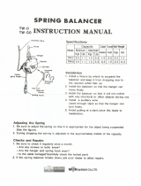
ATTACH DRAWBAR Fig. 8
Move trolley carriage to within 6" of front mounting
bracket by manually turning large pulley at powerhead.
If operator is supplied with a brake, pull disconnect
bolt at back of brake mounting plate to disengage
brake.
Attach quick release arm to trolley carriage. With quick
release arm in vertical position, attach curved portion of
arm assembly to quick release portion using 5/16 x 1"
cap screws, nuts and lock washers furnished in hard-
ware package.
With door in fully closed position attach remaining end of
arm assembly to door bracket with 3/8 x 1" cap screw,
washers and nuts furnished. Arm should connect to door
bracket at hole nearest in line with top rollers of door. See
Fig. 8
Configuration:
Connect to
Sensor 1 Input
Connect to
Sensor 2 Input
Electric Edge Only X -
Photo Eye Only X -
Photo Eye & Electric Edge Photo Eye Electric Edge
Photo Eye & Photo Eye Photo Eye 1 Photo Eye 2
Monitored Reversing Devices

CLUTCH ADJUSTMENT
DANGER: To avoid serious injury or death
always disconnect electrical power before
adjusting clutch.
The clutch must slip to prevent door damage
or injury if the door hits an obstruction while
moving.
Page 7
5973129-7
123
To adjust clutch sensitivity, remove cotter pin from end of
shaft and tighten castle nut until operator will start to lift
door. If the clutch begins to slip, press the "stop" button
and tighten nut again. Do not turn more than 1/6 turn at a
time. Repeat this procedure until door travels smoothly in
both directions to the fully open and closed positions. See
Fig. 10. After final adjustment, replace and lock cotter pin.
Additional adjustments may be required after a short
breaking in period.
WARNING: Do NOT over tension the clutch.
Note: The clutch is set loose at the factory and must be
adjusted in the field for proper sensitivity.
MINIMUM WIRE SIZE FOR THREE-PHASE MOTORS
Hp Volts 0-25 Ft. 50 Ft. 100 Ft. 150 Ft. 200 Ft.
0.33
230
460
14
14
14
14
14
14
14
14
14
14
0.5
230
460
14
14
14
14
14
14
14
14
14
14
0.75
230
460
14
14
14
14
14
14
14
14
14
14
1
230
460
14
14
14
14
14
14
14
14
14
14
1.5
230
460
14
14
14
14
14
14
14
14
12
14
2
230
460
14
14
14
14
14
14
12
14
12
14
LIMIT ADJUSTMENT and TESTING OF OPERATOR
WARNING: To avoid serious injury or death always
disconnect electrical power before adjusting limit
switches.
COTTER PIN
CASTLE NUT
CLUTCH SPRING
WASHER
LARGE PULLEY
CLUTCH DISK
CLUTCH PLATE
FIG. 10
LIMIT NUT
LIMIT NUT KEEPER
"CLOSE" LIMIT SWITCH "OPEN" LIMIT SWITCH
FIG. 9
This operator has been supplied from the factory with
constant pressure to close. It is advisable that you test the
operator and set limit switches in this mode. With quick
release arm still disconnected, turn power on to operator
and press open button. This insures that the operator is
running in the correct direction. Press Stop button after unit
has run a few feet, then close the operator so the trolley
carriage is within 6" of front mounting bracket and attach
quick release arm to trolley carriage. Set close limit at this
position by depressing limit nut keeper and turning nut
towards the close limit switch (see Fig. 9) until limit switch
is activated (clicks).
Note: In certain applications the limit
switches may be reversed from what is shown. At this time
the clutch must be adjusted, see clutch adjustment.
When clutch is properly adjusted, raise door to the full
open position and stop door at the desired height and
set the open limit nut as described above. After setting
limit nuts in desired position, make certain that limit nut
keeper is engaged in grooves on limit nuts. When making
fine adjustments, turn nut no more than 1/4 turn at a time.
To stop door earlier, move limit nut closer to limit switch.
To stop door later, move nut away from limit switch.
Hp Volts 0-25 Ft. 50 Ft. 100 Ft. 150 Ft. 200 Ft.
0.33
115
230
14
14
12
14
10
14
8
14
6
12
0.5
115
230
14
14
12
14
10
14
8
14
6
12
0.75
115
230
12
14
10
14
8
14
6
12
4
10
1
115
230
12
14
10
14
8
14
6
12
4
10
1.5 230 14 14 12 10 8
MINIMUM WIRE SIZE FOR SINGLE-PHASE MOTORS

Page 8
5973129-8
OPEN
CLOSE
STOP
COM
SEN1
SEN1
SEN2
SEN2
ILOCK
COM
SINGL
AUXIN1
AUXIN1
COM
24VAC
24VAC
24VAC
TRANSFORMER
BRAKE+
BRAKE-
TCLIP
PROG
AUX
LIMITS/RADIO
ILOCK
ADJ
OPEN
CLOSE
STOP
HIGH
VOLTAGE
TCS
Program Button
Auxiliary Board Connection
Timer To Close
Connection
Chain Hoist Interlock
Limit Switch/Radio Control
Connection
LED Disaplay
Open/Close/Stop
Buttons
24V DC Brake Connection
24V AC Power Connection
Terminal Block 1
Terminal Block 2
High Voltage Wire
Harness Connection
FIGURE 11
LIGHT CCM NO1 SERC1
NC1
NO2C2
NC2
ON/OFF
OPEN
CLOSE
ON/OFF
24VDC+
24VDC-
24VAC
24VAC
Terminal Block 3
24V DC Power Connection
Auxiliary Board Connection
CCM Jumper
Closing Motion
CCM Jumper
Opening Motion
FIGURE 12
AUXILIARY BOARD (OPTIONAL)
LOGIC BOARD FUNCTIONS AND CONNECTIONS

Page 9
5973129-9
LOGIC BOARD PROGRAMMING
The logic board may be factory programmed, if not follow the instructions below.
Programming Notes:
1. Use the Open, Close and Stop buttons on the board when programming.
2.
Open button used to increase time or turn functions 'On' & 'Off'.
3.
Close button used to decrease time or page through choices.
4.
Stop button used to continue to next option and end programming.
1. To start the program mode, locate the program and stop button on the logic board (see figures 11 & 12), press
and hold both program and stop buttons for 5 seconds.
2. "
WIRING MODE" will display, there are three options to choose from as shown below.
NORMAL SR5 - 3 button momentary contact on open, close, and stop with 1 second delay on open and close
with provisions for connection of a reversing device(s).
CSTP OPN/CLS RD - Constant pressure to open and close.
CSTP CLS ONLY RC - 3 button momentary contact on open and stop, constant pressure to close.
3. Select the wiring type by using the
close button to page through the wiring modes. Press the stop button to
continue to the next option.
4. "
SENSOR 1 TYPE" will display, there are two options to choose from, "PHOTO EYE" or "ELECTRIC EDGE".
Use the
close button to page through the choices. Press the stop button to continue to the next option.
Note: The photo eye or an electric edge must be monitored.
5. "
SENSOR 2 TYPE" will display, there are three options, "NONE CONNECTED", "PHOTO EYE", or
"
ELECTRIC EDGE". Use the close button to page through the choices. Press the stop button to continue to
next option.
Note: The photo eye or an electric edge must be monitored.
6. "
TIMER TO CLOSE", this will display if there is a timer to close connected to the logic board. The timer to
close can be set from 10 seconds to 240 seconds in 1 second intervals. Use the open and close buttons on
the board to set the time. Press the
stop button to continue to the next option.
7. "
AUX INPUT 1 TYPE" will display. This is an auxiliary contact used to open the door. There are five options to
choose from as shown below. Use the
close button to page through the choices. Press the stop button to
continue to next option.
NONE CONNECTED - No device required
REVERSING (N.C.) - Non-monitored, normally closed reversing device.
REVERSING (N.O.) - Non-monitored, normally open reversing device.
VENTILATION (N.O.) - Normally open contact used to open the door for ventalation such as a carbon
monoxide detector. The door can be opened to a determined height by setting the
open run time.
FIRE STATION (N.O.) - Normally open contact used to open the door such as a pull cord. The door will fully
open and then close after a determined time has been set.

Page 10
5973129-10
8. If "
VENTILATION (N.O)" was selected, the distance the door is to open needs to be set. The display should read "OPEN
VENT TIME" , the distance is determined by the number of seconds the door will open. This is done in 1 second intervals
from 3 to 30 seconds. Use the open and close buttons on the board to set the time. Press the
stop button to continue to
the next option.
9. If "
FIRE STATION (N.O)" was selected, the timer to close needs to be set. "FS: TIME TO CLOSE" will display. This is
done in 10 second intervals from 60 to 900 seconds. Use the open and close buttons on the board to set the time. Press
the
stop button to continue to the next option.
10. "
AUX INPUT 2 TYPE" will display, this is used for a second auxiliary contact to open or close the door. Repeat steps 7
through 9 if a second auxiliary contact is required.
11. "
MIDWAY STOP", this allows the door to stop midway through the open cycle. If a midway stop is not required, select
"
OFF". If the midway stop is required, select "ON". Press the stop button to continue.
12. If a midway stop is requried, "
MIDWAY TIME" will display, the distance is determined by the number of seconds the door
will open. This is done in 1 second intervals from 3 to 30 seconds. Use the open and close buttons on the board to set
the time. Press the
stop button to continue to the next option.
13. If there is no auxiliary board, then programming the logic board is complete. If there is an auxiliary board, then continue
through steps 14 - 16.
14. "
LIGHT ON TIME" will display, this is used to turn on a light and shut off a light after a determined amount of time. This is
done in 10 second intervals from 10 to 240 seconds. Use the open and close buttons on the board to set the time. Press
the
stop button to continue to the next option.
15. "
CLOSE WARNING LIGHT" will display, this is used to activate a warning light a determined amount of time before the
door goes in the close motion. If no warning light is required, select "
OFF". If a warning light is required, select "ON".
Press the
stop button to continue.
16. If a warning light is "
ON", "WARNING TIME" will display. The time is set in 1 second intervals from 3 seconds to 10
seconds. If there is a timer to close, the close warning light time must be set lower than the timer to close time. Use the
open and close buttons on the board to set the time. Press the
stop button to end programing.
SPECIAL PROGRAMMING INSTRUCTIONS
The maximum run timer and reverse limits option are factory set and you are not required to set these in the initial set up.
However, in the event that you need to modify either one of these options, use the instructions below.
Maximum Run Timer
To help prevent damage to the operator, it is supplied with a maximum run timer (factory set at 40 seconds) with a maximum
run time of 120 seconds.
To change factory default, press and hold the stop button and program button until you enter the programing mode. Once in
the program, release both buttons. Then press and hold the program button for approximately 30 seconds, or until an
asterisk shows up on the screen. Then release the program button. You can now use the stop button to advance through the
program until you see the maximum run timer. Use the open and close buttons to adjust the time. Once finished, use the
stop button to advance the rest of the way through the program.
Reverse Limits
For ease of changing the operator position, it has been supplied with a “reverse limits” option. If you need to switch the open
and close limit switches, press and hold the stop button and program button until you enter the programming mode. Once in
the program, release both buttons. Then press and hold the program button for approximately 30 seconds, or until an
asterisk shows up on the screen. Then release the program button. You can now use the stop button to advance through the
program until you see the reverse limits option. Use the open and close buttons to select “yes” or “no” (factory default is “no”).
Once finished, use the stop button to advance the rest of the way through the program.

Page 11
5973129-11
USER AND IMPORTANT SAFETY INSTRUCTIONS
WARNING - To reduce the risk of severe injury or death:
1. READ AND FOLLOW ALL INSTRUCTIONS.
2. Never let children operate or play with door controls. Keep the remote control (where provided) away from children.
3. Personnel should keep away from a door in motion and keep the moving door in sight until it is completely closed or
opened. NO ONE SHOULD CROSS THE PATH OF A MOVING DOOR.
4. Test the doors reversing features at least once a month per instructions supplied with reversing device. If limit
switches require adjusting, reversing devices must also be re-tested. Failure to adjust the operator properly, may
cause severe injury or death.
5. For products having a manual release, if possible, use the manual release only when the door is closed. Use
caution when using this release when the door is in the open position. Weak or broken springs may cause the door
to fall rapidly, causing severe injury or death.
6. KEEP DOORS PROPERLY OPERATING AND BALANCED. See Door Manufacturer's Owner's Manual. An
improperly operating or balanced door could cause severe injury or death. Only have a trained door systems
technician make repairs to cables, springs and other hardware.
7. Only use Raynor approved reversing device as explained on front cover of this installation booklet. Failure to use a
Raynor approved device may cause severe injury or death.
8. SAVE THESE INSTRUCTIONS.
OPERATING INSTRUCTIONS:
Operating the 3-Button Control Station:
1.
Press OPEN button (The door should move in the open direction).
2. Press STOP button (The door should stop).
3. Press the CLOSE button (The door should move in the close direction).
4. Release the close button and the door should stop if set up for constant pressure (The door should continue
if set up for momentary contact
).
5. Press stop button (The dooor should stop).
How to verify limit switches are adjusted properly:
1.
Press open button and allow door to fully open. The limit should be adjusted so that bottom of door is about an inch
above the bottom of the header.
2. Press close button and allow door to fully close. The door should just hit the floor and stop. If close limit is set to low, the
door may hit floor and bounce back up. This can cause damage to door and operator. If door does not completely seal
against floor, the problem may be with the floor being un-even and not a problem with the operator.
If the limits are not set properly, and need adjustment, remove power and adjust limits (Refer to page 7).
TEST THE ENTRAPMENT PROTECTION DEVICES:
1.
Open the door.
2. Place an obstruction in the path of the photo eyes or electric sensing edge.
3. Press the CLOSE button. The door should not close if photo eyes are installed. The door should close to
obstruction and reverse if sensing edge is installed.
4. Remove the obstruction.
5. Press CLOSE button. The door should close.
If door did NOT reverse from obstruction, check entrapment devices.

Page 12
5973129-12
INSPECTION AND ADJUSTMENTS
WARNING: Repairs and adjustments to the
door or operator should only be made
by a qualified door installer.
1.
2.
3.
4.
5.
6.
Inspect and tighten (if necessary) all bolts and nuts.
Periodically check that all labels shown on page 13
are installed. If labels are missing, contact your nearest
Raynor dealer.
Adjust chain tension on trolley carriage (see Fig. 3).
This chain could stretch slightly during first year of
operation.
Adjust clutch as shown in Fig. 10, if necessary.
Adjustment may be required after a short break-in
period.
If necessary, adjust limit nuts as described in Fig. 9.
Check V-belt for wear and replace if necessary. Also
check V-belt tension (about 1/2 inch deflection when ap-
plying pressure with finger). Adjust tension by loosening
motor bolts and moving motor toward the rear of the
operator.
7.
8.
9.
CAUTION:Do not reset overload until problem
is identified. Damage to door and operator or
personal injury could result if cause of tripping
is not corrected.
10. Manual Reset Overload:
Single Phase:
Three Phase:
Check manual operation of door. Refer to
installation instructions 800, page 5972558-1
for guidelines.
Test all reversing devices once a month for proper
operation.
Test all options that may have been supplied with the
operator to insure they are working properly.
The overload is properly
sized, at the factory, for normal door operation. If over-
load trips, manually check mechanical operation of door
and operator to be certain both work freely.
When overload trips, it cuts power to the
entire unit. To reset, press reset button on outside of
control box.
When overload trips, it cuts power to the
24 volt control circuit only. To reset, open control box
cover and press red reset button.
PERIODIC INSPECTION AND MAINTENANCE
Your Raynor electric door operator was designed to give dependable service with a minimum amount of maintenance.
After proper installation and adjustment, by a qualified installer, little is required in the way of miantenance except for
periodic inspection and lubrication as follows:
LUBRICATION
All Raynor operators are supplied with continuous rated
motors and under normal conditions require no oiling.
Lubricate rails with paraffin or graphite. Do not use oil or
grease on trolley drive chain or rails as it could drip onto
door.

Page 13
5973129-13
2
3
1
451112
6
8
7
10
9
Status Light Definition
8. Single (D15)
On = Single button activated.
Off = Single button not activated.
9. Non -Monitored (D18)
Aux Input 2
On = Non monitored circuit is closed.
Off = Non monitored circuit is open.
10. Non-Monitored (D19)
Aux Input 1
On = Non monitored circuit is closed.
Off = Non monitored circuit is open.
ON BOARD STATUS LIGHTS
11. Limit 1 - Open (D16)
12. Limit 2 - Close (D17)
On = Limit switch is activated.
Off = Limit switch is not activated.
On = Limit switch is activated.
Off = Limit switch is not activated.
1. Stop (D14)
On = Stop button connected and working.
Off = Stop button pressed or NOT connected.
On = Open button sending signal (pressed)
Off = Open button is not sending signal.
2. Open (D12)
6. I-Lock (D24)
7. I-Lock (D23)
On = Chain hoist interlock circuit is open. (chain hoist is pulled,
malfunctioned, or jumper is missing for non-chain hoist units)
Off = Chain hoist circuit is closed. (normal operation)
On = Lock interlock circuit on TB-2 is open. (Jumper is missing or
interlock circuit has malfunctioned)
Off = Lock interlock circuit on TB-2 is closed. (normal operation)
3. Close (D13)
On= Close button sending signal (pressed)
Off = Close button is not sending signal.
4. Sen 1 (D20)
5. Sen 2 (D21)
On = Sensor 1 hooked up & working
Off = Sensor 1 activated, or has malfunctioned.
On = Sensor 2 hooked up & working/ or sensor 2 not programed.
Off = Sensor 2 activated, or has malfunctioned.

Page 14
5973129-14
Display Definition
"Partially Open" This message will display anytime the door is not on the fully open or close limit switch.
"Opening Door Running" This message will display when the door is running in the open direction.
"Closing Door Running" This message will display when the door is running in the closed direction.
"Aux Board Connected"
"Lock Bar Detected"
This message will display whenever the open button is pressed and the limit nut does
NOT come off the close limit switch with in a certain amount of time. If the door is stuck
down for any reason, the open cycle will shut down to save damage to the door.
"Close in XX sec."
This message will display anytime the board is receiving a signal from the close limit
switch and the open button is pushed.
This message will display when the operator is powered up, and the auxiliary contacts
board is connected to the main board via wiring harness.
"At Open Limit"
This message will display anytime the board is not receiving a signal from the Aux 2
when close button is pressed. Whether it is not connected, activated, or has
malfunctioned. If no sensor is required on Aux 2, select "None Connected" in the
program menu.
This message will display anytime the board is receiving a signal from the open limit
switch and the open button is pushed.
This message will display anytime the board is not receiving a signal from the sensor 2,
when close button is pressed. Whether it is not connected, activated, or has
malfunctioned. If no sensor is required on sensor 2, select "None Connected" in the
program.
"Locked Out"
The LCD display will read "locked Out" when either the on board chain hoist interlock, or
the door interlock, on terminal block 2 is activated. These connections will have a jumper
when not required.
When in Timer to close mode (TCS), and door is in the open position, if the stop button
is pressed while timer is still counting down it will pause the timer until either the open or
close button is pressed.
When in timer to close mode, and the door is in the open position, the display will read
the amount of time in seconds that is remaining until door closes. You can activate the
stop button to pause this countdown.
LCD Display Messages
"Sensor 1 activated"
This message will display anytime the board is not receiving a signal from the sensor 1,
when close button is pressed. Whether it is not connected, activated, or has
malfunctioned.
"Sensor 2 activated"
"At Close Limit"
"TCS Paused"
"Aux 1 activated"
This message will display anytime the board is not receiving a signal from the Aux 1
when close button is pressed. Whether it is not connected, activated, or has
malfunctioned. If no sensor is required on Aux 1, select "None Connected" in the
program.
"Aux 2 activated"

Page 15
5973129-15
SYMPTOM PROBABLECAUSE PROBABLESOLUTION
1.ConnectOperatortopowersource.
2.CheckvoltageatL1&L2forsinglephaseandL1,L2,&L3forthree
phase.
3.Checkforblownfuseortrippedcircuitbreaker.
2.Overloadprotectortripped
inoperator.
1.Resetandcheckforcause.Extern allylocatedonsinglephaseand
intern allylocatedonthreephase.
2.WiringmodesetforRCorRDwiring.
1.SetwiringmodetoSR5momentaryoperation.
See"LogicBoardPrograming"page.
1.Weakbattery. 1.Replacebattery.
2.Incorrecthookup. 1.Refertowiringdiagramfo rproperconnection.
6.Doorwillopenmostoftheway,
butstops
shortoffullyopenand
openbuttonmustbepressedagain
thefullyopenthedoor.
1.Maximumruntimerhastimedout.
Thedefaultsettingis40seconds.For
larg erdoors,maximumruntimemay
needtobesethigher.
1.SeeintructionsforsettingofMaximumrun timer.
7.
Thereisadelaybetweenwhen
openorclosedbuttonispressed,
anddoorbeginstomove.
1.Thisisnormaloperation.Thisdelay
isinplacetokeepdoorfromreversing
instantlyandeliminatestressonrollers
andcables.
1.Normaloperation,nosolution.
1.Sunlightisblockingthereceiving
photo
eye.
1.Movephotoeye'sawayfromopening,orswa ptherecieverand
transmittertokeeprec ieveroutofthesunlight.
2.Faultyphotoeye's 1.Replaceph otoeye's.
8.Sensorsarelignedupbutstillnot
sendingsignaltothelogicboard.
5.Doorcloseswhenopenbuttonis
pressedanddoor
openswhenclose
buttonispressed.
1.Threephasepowersupplyis
connectedoutofphase.
2.Open&closebuttonsnotwired
correctly.
1.Interchangeanytwoincomingpowersup plyleads.
1.Refertowiringdiagramfo rproperconnection.
4.Opera to rdoesNOTshutoffat
fullyopenorclosedposition.
1.
Limitnu tsnotproperlyadjusted. 1.Seelimitswitchadjustmentin installationinstru ctions.
2.Limitdrivechainisbrokenor
inoperative.
1.Replacechain,checkdrivemechanism,andre‐adjustlimit
switches.
3.Limitswitchisdamaged. 1.Checklimitswitchoperationandreplaceifn ecessary.
COMMERCIALOPERATORTROUBLESHOOTONGLIST
1.ChainHoistinterlockswitchisactivatedorhasmalfunctioned,or
thejump erismissingonnonchainhoistunits.("Logicboard
functions&connections"page.)
2.InterlockdeviceonTerminalBloc k2hasmalfunctionedorjumper
missing.("Logicboardfunctions&connections"page.)
3.DisplayonLogicboardreads
"LockedOut"
1.TheoperatorwillNOTrespondto
anycommands.
1.Makesurethelogicboardisprogramedforthecorrectreversing
device.Ifusingaphotoeye,makesur etheprogramissetforphoto
eye.Samegoesforaelectricedge. See"LogicBoa rdPrograming"
page.
4.Improperprogramingofreversing
device.
1.No PowertoOperator
1.Reversingdevicenothookedup,or
notworkingproperly.
3.Reversingdeviceisactivated.
1.Seewiringdiagramforproperconnectionofreversingdevices.
1.Removeobstruction.
2.Opera to ronlyworkswith
constantpressureonclo sebutton.
3.Radio contro lwillnotwork.

Page 165973129-16
LABEL PLACEMENT FOR TROLLEY OPERATORS
* Label Supplied With Operator
** Label Supplied With Raynor Door
NOTE: Placement of Labels may vary
from what is shown.
**Spring Warning Tag
*Push Button Placard
Locate Near Push Button
**Door Safety Label
**Bottom Fixture Danger Label
**Bottom Fixture Danger Label
**Door Safety Label
*Trolley Disconnect Instruction Label
/