Raynor Ultra II Installation guide

Category
Garage Door Opener
Type
Installation guide
CONTENTS
Preparation . . . . . . . . . . . . . . . .2-5
Assembly . . . . . . . . . . . . . . . . .6-7
Installation . . . . . . . . . . . . . . . 8-15
Install the Door Control. . . . . . 16-17
Install the Protector System
®
. . 18-21
Power. . . . . . . . . . . . . . . . . . 22-23
Adjustments . . . . . . . . . . . . . 24-26
Operation . . . . . . . . . . . . . . . 27-33
Maintenance . . . . . . . . . . . . . . . 34
Troubleshooting. . . . . . . . . . . 35-36
Accessories. . . . . . . . . . . . . . . . 37
Warranty. . . . . . . . . . . . . . . . . . 38
Repair Parts . . . . . . . . . . . . . 39-40
WiFi
®
Garage
Door Opener
Raynor Garage Doors
1101 E. River Road
Dixon, Illinois 61021
Please read this manual and the enclosed safety materials carefully!
Fasten the manual near the garage door after installation.
The door WILL NOT CLOSE unless the Protector System
®
is connected and properly
aligned.
Periodic checks of the garage door opener are required to ensure safe operation.
This garage door opener is ONLY compatible with MyQ
®
and Security+ 2.0™
accessories.
DO NOT enable the Timer-to-Close feature if you are installing the garage door
opener on a one-piece door. The Timer-to-Close is to be used ONLY with
sectional doors.
Attach warning labels to the location indicated on label.
www.raynor.com
Model 8587WRGD
Chain Drive Garage
Door Opener
FOR RESIDENTIAL USE ONLY
SERIAL NUMBER:
Please write the MyQ Serial number in the box above. See page 2.
Register online at: http://blog.raynor.com/warranty-registration
2
MyQ
®
Serial Number
Write down the following information for future reference:
MyQ
®
Serial Number:
MyQ
®
Serial Number
Accessory Setup Code
Product S/N
Accessory Setup Code:
Product S/N:
Date of Purchase:
/ /
Safety Symbol and Signal Word Review
This garage door opener has been designed and tested to offer safe service provided it is installed,
operated, maintained and tested in strictaccordance with the instructions and warningscontained in this
manual.
When you see these Safety Symbols and Signal Wordson the following pages,they will alert you to the
possibility ofserious injury or death if you do not comply with the warningsthataccompanythem.The
hazard may come from something mechanical or from electric shock.Read the warningscarefully.
Mechanical
Electrical
When you see thisSignal Word on the following pages, itwill alert you to the possibility ofdamage to
your garage door and/or the garage door opener if you do not complywith the cautionary statements that
accompany it. Read them carefully.
Unattended Operation
The Timer-to-Close (TTC) feature,the MyQ
®
Smartphone Control app, and MyQ
®
Garage Door and
Gate Monitor are examplesofunattended close and are to be used ONLY with sectional doors. Any
device or feature that allows the door to close without being in the line of sight ofthe door is considered
unattended close. The Timer-to-Close (TTC) feature, the MyQ
®
Smartphone Control,and anyother
MyQ
®
devicesare to be used ONLY with sectional doors.
Preparation
3
Test the Wi-Fi
®
Signal Strength
Before You Begin
You will need:
l Wi-Fi enabled smartphone,tablet or laptop
l Broadband InternetConnection
l Wi-Fi
®
signal in the garage
l Password for your home network
l MyQ Serial number (located on the garage door opener.)
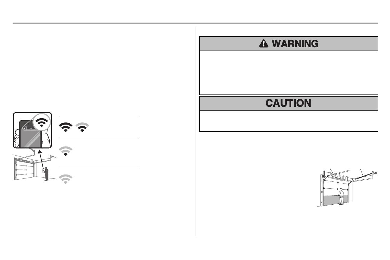
Test the Wi-Fi
®
Signal Strength
Make sure your mobile device isconnected to your Wi-Fi network.Hold your mobile device in the place
where your garage door opener will be installed and check the Wi-Fi signal strength.
Check Signal Strength. If you see:
Wi-Fi signal is strong.
The garage door opener will
connect to your Wi-Fi
network.
Wi-Fi signal is weak.
The garage door opener may connect
to your Wi-Fi network. If not, try one
of the options below to improve the
Wi-Fi signal:
No Wi-Fi signal.
The garage door opener will not be
able to connect to your Wi-Fi
network. Try one of the options
below to improve the Wi-Fi signal:
• Move your router closer to the garage
door opener to minimize interference from
walls and other objects
• Buy a Wi-Fi range extender
See page 29 to connect the garage door opener mobile device
Check the Door
To preventpossible SERIOUSINJURYor DEATH:
l ALWAYS call a trained door systems technician if garage door binds, sticks,or is outof
balance.An unbalanced garage door may NOT reverse when required.
l NEVER try to loosen,move or adjust garage door, door springs,cables, pulleys, brackets or
their hardware, ALLofwhich are under EXTREME tension.
l Disable ALLlocksand remove ALLropes connected to garage door BEFORE installation
and operating garage door opener to avoid entanglement.
To preventdamage to garage door and opener:
l ALWAYS disable locksBEFORE installing and operating the opener.
l ONLY operate garage door opener at 120V, 60Hz to avoid malfunction and damage.
1. Disable locksand remove any ropes connected to
the garage door.
2. Lift the door halfwayup. Release the door.If
balanced,it should stayin place,supported entirely
by its springs.
3. Raise and lower the door to checkfor binding or
sticking. Ifyour door binds,sticks, or is outof balance,
call a trained door systems technician.
4. Checkthe seal on the bottom of the door. Any gap
between the floor and the bottom of the door must not
exceed 1/4inch (6 mm).Otherwise, the safety
reversal systemmay notwork properly.
5. The opener should be installed above the center of
the door.Ifthere is a torsion spring or center bearing
plate in the way of the header bracket, itmaybe
installed within 4feet (1.2m) to the leftor rightof the
door center.See page 9.
Torsion
Spring
Ex
tension
Spring
OR
Preparation
4
Tools Needed
3/16
5/32
5/16
7/16
1/2
5/8
9/16
1/4
7/16
Preparation
5
Carton Inventory
Accessories will varydepending on the garage door opener model purchased. Depending on your
specific model, other accessoriesmay be included with your garage door opener.The instructionsfor
these accessories will be attached to the accessoryand are notincluded in this manual.The images
throughout this manual are for reference and your productmaylookdifferent.
Garage Door Opener Assembly
A. Header bracket
B. Pulley and bracket
C. Door bracket
D. Curved door arm
E. Straight door arm
F. Trolley
G. Emergency release rope and handle
H. Rail
I. Garage door opener
J. Chain spreader
K. Chassis support bracket
L. Chain
M. Door control (Smart Control Panel
®
880RGD)
N. White and red/white wire
O. The Protector System
®
Safety reversing sensorswith white and white/black wire attached:Sending senor (1),
receiving sensor (1), and safetysensor brackets(2)
P. Safety labels and literature
Q. Rail grease
R. Remote control 893RGX
Hardware
Assembly
Chassis Support Bracket Hardware Chain Spreader Hardware
Screw #8-32 x 3/8" (2) Screw #8-32 x 3/8" (2)
HexBolts1/4"-20 x 5/8" (2) Rail Hardware
LockWashers (2)
Washered Bolts and Lock Washer [mounted in the
top of the garage door opener
Washered Bolt 5/16"-18 x 1/2" (2)
Installation
HexBolt 5/16"-18 x 7/8" (4) Self-Threading Screw 1/4"-14 x 5/8" (2)
Lag Screw 5/16"-9 x 1-5/8" (2) Ring Fastener (3)
Lag Screw 5/16"-18 x 1-5/8" (2) Carriage Bolt1/4"-20 x 1/2" (2)
Clevis Pin 5/16" x 2-3/4" (1) Wing Nut1/4"-20 (2)
Clevis Pin 5/16" x 1-1/4" (1) HexBolt 1/4"-20 x 5/8" (2)
Clevis Pin 5/16" x 1" (1) LockNut1/4"-20 (2)
Nut5/16"-18 (4) Lag Screw 1/4" x 1-1/2" (4)
LockWasher 5/16"-16 (4)
Door Control Hardware
Screw 6AB x 1-1/4" (2) Drywall Anchors (2)
Screw 6-32 x 1" (2) Insulated Staples
A
B
C
K
J
I
P
D
E
F
H
G
L
M
N
Q
O
R
Not
Provided
Not
Provided
Preparation
6
Assembly
1 Attach the Rail to the Garage Door Opener
To avoid SERIOUS damage to garage door opener,use ONLY those bolts/fasteners mounted in the
top of the opener.
NOTE: ONLY use the bolts removed from the garage door opener. Place the garage door opener on
the packing material to prevent scratching.
1. Remove boltand lock nutfrom the top of the garage door opener.
2. Align the rail and the styrofoam over the sprocket. Cut the tape from the rail, chain, and
styrofoam.
3. Fasten the rail with the previously removed washered bolt and locknut.
4. Position the chain around the garage door opener sprocket.
5. Attach the chain spreader to the garage door opener with screws.
6. Guide the chain around the selected groove in the chain spreader, to engage either the 8-
tooth or 6-tooth sprocket.
NOTE: The 6-tooth sprocket is for use with Carriage House Doors and the 8-tooth sprocket is
for use with regular doors.
Washered Bolt
5/16"-18x1/2"
(Mounted
in the garage
door opener)
HARDWARE
Lock Nut
(Mounted in the
garage door opener)
Lock
Nut
Washered Bolt
5/16"-18x1/2"
Hex Screws 8-32x1"
Washers
Chain Spreader6-Tooth
Sprocket
8-Tooth
Sprocket
Chain Spreader
Motor Unit Mounting Plate Motor Unit Mounting Plate
7
Assembly
2 Attach the Chassis Support Bracket
To avoid possible SERIOUS INJURY to finger from moving garage door opener:
l ALWAYS keep hand clear of sprocketwhile operating opener.
l Securelyattach sprocket cover BEFORE operating.
1. Position the chassis supportbracket on the unit.
2. Attach the bracketto the rail with 1/4"-20x5/8" hex bolts and lock washers. Do not overtighten.
3. Attach the bracketto the opener by inserting a 5/16"-18x1/2" washered screw through a hole
in each side flange and a matching hole in the bracket. Complete the connection by inserting
the #8-32x3/8" screw through the back flange and the hole in rail support.
Washerd Bolt
5/16"-18x1/2"
Screw
#8-32x3/8"
Hex Bolt
1/4"-20x5/8"
Lock
Washer
3 Tighten the Chain
1. Loosen the inner nut and lock washer on the trolley threaded shaft.
2. Tighten the outer nutuntil the chain is a 1/2 inch above the base of the rail at the midpointof
the rail.
3. Re-tighten the inner nut.
Slack in the chain is normal when the door is closed.No readjustmentis necessary.
NOTE: Sprocket noise can result if the chain is too loose. During future maintenance, ALWAYS pull the
emergency release handle to disconnect the trolley before adjusting the chain.
8
Installation
IMPORTANT INSTALLATION INSTRUCTIONS
To reduce the risk of SEVERE INJURY or DEATH:
1. READANDFOLLOW ALL INSTALLATION WARNINGS AND INSTRUCTIONS.
2. Install garage door opener ONLY on properly balanced and lubricated garage door.An
improperly balanced door may NOT reverse when required and could result in SEVERE
INJURY or DEATH.
3. ALL repairs to cables,spring assemblies and other hardware MUSTbe made by a trained
door systems technician BEFORE installing opener.
4. Disable ALL locks and remove ALL ropesconnected to garage door BEFORE installing
opener to avoid entanglement.
5. Install garage door opener 7 feet (2.13 m) or more above floor.
6. Mountthe emergency release within reach,but at least 6 feet (1.83 m) above the floor and
avoiding contactwith vehicles to avoid accidental release.
7. NEVER connect garage door opener to power source until instructed to do so.
8. NEVERwear watches, rings or loose clothing while installing or servicing opener.They
could be caught in garage door or opener mechanisms.
9. Install wall-mounted garage door control:
l within sight ofthe garage door.
l out of reach ofchildren at minimumheight of5 feet (1.5 m).
l away from ALL moving partsof the door.
10. Place entrapment warning label on wall nextto garage door control.
11. Place manual release/safetyreverse test label in plain view on inside ofgarage door.
12. Upon completion of installation, test safetyreversal system. Door MUSTreverse on contact
with a 1-1/2" (3.8 cm) high object(or a 2x4 laid flat) on the floor.
13. To avoid SERIOUS PERSONAL INJURY or DEATH from electrocution,disconnect ALL
electricpower BEFORE performing ANY service or maintenance.
14. DO NOT enable the Timer-to-Close functionalityifoperating either one-piece or swinging
garage doors.To be enabled ONLY when operating a sectional door.
9
Installation
1 Determine the Header Bracket Location
To preventpossible SERIOUS INJURY or DEATH:
l Header bracket MUST be RIGIDLY fastened to structural support on header wall or ceiling,
otherwise garage door might NOT reverse when required.DO NOT install header bracket
over drywall.
l Concrete anchors MUSTbe used if mounting header bracket or 2x4 into masonry.
l NEVER try to loosen,move or adjust garage door, springs,cables,pulleys, brackets,or their
hardware, ALL of which are under EXTREME tension.
l ALWAYS call a trained door systems technician if garage door binds, sticks,or is outof
balance.An unbalanced garage door might NOT reverse when required.
l DO NOTenable the Timer-to-Close functionalityif operating either one-piece or swinging
garage doors.To be enabled ONLY when operating a sectional door.
Close the door and mark the inside vertical centerline ofthe garage door.
Extend the line onto the header wall above the door.You can fasten the header bracketwithin 4 feet
(1.22 m) of the leftor right of the door center only if a torsion spring or center bearing plate is in the way;
or you can attach itto the ceiling when clearance is minimal.(It maybe mounted on the wall upside down
if necessary, to gain approximately 1/2" (1 cm).Ifyou need to install the header bracket on a 2x4 (on wall
or ceiling), use lag screws (not provided) to securely fasten the 2x4 to structural supports.
Open your door to the highestpoint oftravel as shown. Draw an intersecting horizontal line on the
header wall 2" (5 cm) above the high point. This heightwill provide travel clearance for the top edge of
the door.
NOTE: If the total number of inches exceeds the height available in your garage, use the maximum
height possible, or refer to page 10 for ceiling installation.
Header Wall
Unfinished
Ceiling
Vertical Centerline
of Garage Door
2x4
2x4
Structural
Supports
Level
(Optional)
OPTIONAL
CEILING
MOUNT FOR
HEADER
BRACKET
Sectional door with curved track
Header Wall
Track
2" (5 cm)
Highest Point
of Travel
Door
10
Installation
2 Install the Header Bracket
You can attach the header bracketeither to the wall above the garage door, or to the ceiling. Follow the
instructionswhich will work best for your particular requirements.Do not install the header bracket over
drywall. If installing into masonry, use concrete anchors (not provided).
HARDWARE
Lag Screw 5/16"-9x1-5/8"
OPTION A WALL INSTALLATION
1. Center the bracketon the vertical centerline with the bottomedge of the bracket on the
horizontal line as shown (with the arrow pointing toward the ceiling).
2. Mark the vertical setofbracketholes (do notuse the holes designated for ceiling mount).Drill
3/16" pilot holes and fasten the bracket securely to a structural supportwith lag screws.
Wall Mount
Optional
Mounting
Holes
Vertical
Centerline of
Garage Door
(Header Wall)
Header
Bracket
2x4 Structural
Support
Door Spring
(Garage Door)
Highest Point of
Garage Door
Travel
Horizontal
Line
Lag Screw
5/16" - 9 x
1-5/8"
OPTION B CEILING INSTALLATION
1. Extend the vertical centerline onto the ceiling as shown.
2. Center the bracketon the vertical mark, no more than 6" (15 cm) from the wall. Make sure the
arrow is pointing toward the wall. The bracketcan be mounted flush against the ceiling when
clearance is minimal.
3. Mark the side holes. Drill 3/16" pilot holes and fasten bracketsecurely to a structural support
with lag screws.
(Header Wall)
Ceiling
Mounting Holes
(Finished Ceiling)
Vertical
Centerline of
Garage Door
Header
Bracket
6" (15 cm)
Maximum
Door Spring
(Garage Door)
Lag Screw
5/16" - 9 x 1-5/8"
11
Installation
3 Attach the Rail to the Header Bracket
1. Align the rail with the header bracket. Insertthe clevis pin through the holesin the header
bracketand rail.Secure with the ring fastener.
NOTE: Use the packing material as a protective base for the garage door opener.
HARDWARE
Clevis Pin 5/16" x 2-3/4" Ring Fastener
Ring
Fastener
Clevis Pin
5/16" X 2-3/4"
4 Position the Garage Door Opener
To preventdamage to garage door, rest garage door opener rail on 2x4 placed on top section of
door.
1. Remove the packing material and lift the garage door opener onto a ladder.
2. Fully open the door and place a 2x4 (laid flat) under the rail.
A 2x4 is ideal for setting the distance between the rail and the door.If the ladder is nottall enough you
will need help at this point.Ifthe door hitsthe trolley when it is raised, pull the trolley release arm down to
disconnectthe inner and outer trolley.Slide the outer trolley toward the garage door opener.The trolley
can remain disconnected until instructed.
Connected Disconnected
12
Installation
5 Hang the Garage Door Opener
To avoid possible SERIOUS INJURY from a falling garage door opener, fasten it SECURELY to
structural supports ofthe garage. Concrete anchors MUSTbe used if installing ANY brackets into
masonry.
Hanging your garage door opener will varydepending on your garage.Two representative installations
are shown.Yours maybe different. Hanging brackets should be angled (Figure 1) to provide rigid
support. On finished ceilings (Figure 2),attach a sturdy metal bracketto structural supports before
installing the opener. This bracket and fastening hardware are notprovided.
1. Measure the distance from each side ofthe motor unitto the structural support.
2. Cut both piecesof the hanging bracket to required lengths.
3. Drill 3/16" pilot holes in the structural supports.
4. Attach one end of each bracket to a supportwith 5/16"-18x1-7/8" lag screws (notprovided).
5. Fasten the opener to the hanging brackets with 5/16"-18x7/8" hex bolts,lock washers and
nuts.
6. Checkto make sure the rail is centered over the door (or in line with the header bracket if the
bracketisnot centered above the door).
7. Remove the 2x4.Operate the door manually. Ifthe door hitsthe rail, raise the header bracket.
NOTE: DO NOT connect power to opener at this time.
FIGURE 1
FIGURE 2
(Not Provided)
Lag Screws
5/16"- 18x1-7/8"
Measure
Distance
Hex Bolt 5/16"- 18x7/8", Lock Washer 5/16", Nut 5/16"-18
FIGURE 3
Not Provided
Finished Ceiling
Unfinished Ceiling
Hex Bolt 5/16"- 18x7/8" Nut 5/16"-18 Lock Washer 5/16"
HARDWARE
13
Installation
6 Install the Light Bulbs
To preventpossible OVERHEATING of the end panel or light socket:
l Use ONLY A19 incandescent (100Wmaximum) or compact fluorescent (26Wmaximum)
lightbulbs.
l DO NOTuse incandescentbulbs larger than 100W.
l DO NOTuse compactfluorescentlight bulbs larger than 26W (100W equivalent).
l DO NOTuse halogen bulbs.
l DO NOTuse short neck or specialty light bulbs.
1. Pull on the top center of the lightlens and rotate the light lens down.
2. Insertan A19 incandescent (100W maximum) or compact fluorescent (26W, 100Wequivalent)
light bulb into the lightsocket.
NOTE: DO NOT use halogen, short neck, or specialty light bulbs as these may overheat the end panel
or light socket. DO NOT use LED bulbs as they may reduce the range or performance of your remote
control(s).
3. Rotate the lensup to close.
or or
7 Attach the Emergency Release Rope and Handle
To preventpossible SERIOUS INJURY or DEATHfrom a falling garage door:
l If possible, use emergency release handle to disengage trolley ONLY when garage door is
CLOSED. Weak or broken springs or unbalanced door could resultin an open door falling
rapidly and/or unexpectedly.
l NEVER use emergency release handle unless garage doorway is clear ofpersons and
obstructions.
l NEVER use handle to pull door open or closed. Ifrope knot becomes untied,you could fall.
1. Insertone end of the emergency release rope through the handle. Make sure thatNOTICE” is
rightside up. Tie a knot at least1 inch (2.5 cm) from the end of the emergencyrelease rope.
2. Insertthe other end of the emergency release rope through the hole in the trolley release arm.
Mount the emergency release within reach, but at least6 feet (1.83m) above the floor,
avoiding contactwith vehicles to prevent accidental release and secure with a knot.
NOTE: If it is necessary to cut the emergency release rope, seal the cut end with a match or lighter to
prevent unraveling. Ensure the emergency release rope and handle are above the top of all vehicles to
avoid entanglement.
Trolley
Relea
se Arm
14
Installation
8 Install the Door Bracket
Fiberglass,aluminum or lightweight steel garage doors WILL REQUIRE reinforcementBEFORE
installation of door bracket.Contact the garage door manufacturer or installing dealer for opener
reinforcement instructions or reinforcementkit.Failure to reinforce the top section as required
according to the door manufacturer mayvoid the door warranty.
A horizontal and vertical reinforcement is needed for
lightweight garage doors (fiberglass,aluminum,steel,
doors with glass panel,etc.) (not provided). A horizontal
reinforcement brace should be long enough to be secured
to two or three vertical supports.A vertical reinforcement
brace should cover the height ofthe top panel. Contact the
garage door manufacturer or installing dealer for opener
reinforcement instructions or reinforcementkit.
NOTE: Many door reinforcement kits provide for direct attachment of the clevis pin and door arm. In this
case you will not need the door bracket; proceed to the next step.
SECTIONALDOORS
1. Center the door bracket on the previously marked vertical centerline used for the header
bracketinstallation. Note correct UP placement,asstamped inside the bracket.
2. Position the top edge of the bracket2"-4" (5-10 cm) below the top edge of the door, OR
directlybelow any structural supportacross the top of the door.
3. Mark,drill holes and install as follows, depending on your door’s construction:
Metal or light weight doors using a vertical angle iron brace between the door panel support and the
door bracket:
l Drill 3/16" fastening holes.Secure the door bracketusing the two selfthreading screws.
(Figure1)
l Alternately,use two 5/16" bolts, lock washers and nuts (not provided). (Figure2)
Metal, insulated or light weight factory reinforced doors:
l Drill 3/16" fastening holes.Secure the door bracketusing the self-threading screws. (Figure3)
Wood Doors:
l Use top and bottom or side to side door bracket holes. Drill 5/16” holes through the door and
secure bracketwith 5/16"-18x2" carriage bolts, lock washers and nuts (not provided).
(Figure4)
NOTE: The 1/4"-14x5/8" self-threading screws are not intended for use on wood doors.
FIGURE 1
FIGURE 3
Vertical Reinforcement
Vertical Centerline
of Garage Door
UP
Door Bracket
Self-Threading Screw
1/4" - 14x 5/8"
Self-Threading
Screw
1/4" - 14x 5/8"
Vertical Centerline
of Garage Door
UP
FIGURE 4
Vertical
Centerline of
Garage Door
Bolt 5/16"-18x2"
(Not provided)
UP
Inside Edge of Door or
Reinforcement Board
FIGURE 2
Vertical Reinforcement
Bolt 5/16"-18x2"
(Not provided)
Lock Washer 5/16"
Nut 5/16"-18
Door Bracket
UP
Vertical
Centerline
of Garage Door
Self-Threading Screw
1/4"-14x5/8"
HARDWARE
15
Installation
9 Connect the Door Arm to the Trolley
IMPORTANT: The groove on the straight door arm MUST face away from the curved door arm.
1. Close the door. Disconnect the trolley bypulling the emergency release handle.Slide the
outer trolley back(awayfrom the door) about 2" (5 cm).
2. Attach the straightdoor arm to the outer trolley using the clevis pin. Attach with the ring
fastener.
3. Attach the curved door arm to the door bracketusing the clevis pin. Attach with the ring
fastener.
4. Align the straightdoor arm with the curved door arm.Select two aligned holes (asfar apartas
possible) and attach using the bolts, nutsand lockwashers.
NOTE: If the holes do not line up, reverse the straight door arm. Select two aligned holes (as far
apart as possible) and attach using the bolts, nuts and lock washers.
5. Pull the emergency release handle toward the garage door opener until the trolley release
arm is horizontal.The trolley will re-engage automatically when the garage door opener is
activated.
Straight
Door Arm
Curved
Door
Arm
(Groove
facing
out)
CORRECT
Straight
Door
Arm
Curved
Door
Arm
INCORRECT
Clevis Pin 5/16"x1-1/4"
Ring Fastener
Clevis Pin
5/16"x1"
Nut 5/16" - 18
Lock
Washer
5/16"
Hex Bolt
5/16" - 18 x 7/8"
HARDWARE
Hex Bolt 5/16"-18x7/8"
Nut 5/16"-18
Lock Washer 5/16"
Clevis Pin 5/16"x1"
Clevis Pin 5/16"x1-1/4"
Ring Fastener
16
Install the Door Control
1 Install the Door Control
To preventpossible SERIOUS INJURY or DEATHfrom electrocution:
l Be sure power is NOT connected BEFORE installing door control.
l ConnectONLY to 12 VOLT low voltage wires.
To preventpossible SERIOUS INJURY or DEATHfrom a closing garage door:
l Install door control within sight ofgarage door, out of reach of children at a minimum height of
5 feet (1.5 m),and away from ALL moving parts ofdoor.
l NEVER permit children to operate or playwith door control push buttons or remote control
transmitters.
l Activate door ONLY when it can be seen clearly,isproperly adjusted, and there are no
obstructions to door travel.
l ALWAYS keep garage door in sightuntil completelyclosed.NEVER permitanyone to cross
path of closing garage door.
INTRODUCTION
Compatible with MyQ
®
and Security+ 2.0™ accessories, see page 37. Your garage door opener is
compatible with up to 2 Smart Control Panelsor 4 of any other Security+ 2.0™ door controls.
NOTE:Older Raynor door controls and third party products are not compatible.
Install the door control within sight ofthe door at a minimum height of5 feet (1.5 m) where small children
cannot reach,and away from the moving parts ofthe door. For gang boxinstallations it is notnecessary
to drill holes or install the drywall anchors.Use the existing holes in the gang box.
NOTE: Your productmay look different than the illustrations.
HARDWARE
Scre
w
6ABx1" (2)
Drywall
Anchors
(2)
Screw
6-32x1"
(2)
1. Strip 7/16 inch (11 mm) of insulation from one end of the wire and separate the wires.
2. Connect one wire to each of the two screwson the back ofthe door control.The wires can be
connected to either screw.
PRE-WIREDINSTALLATIONS:Choose any two wires to connect,note which wires are used
so the correctwires are connected at the garage door opener in a later step.
3. Mark the location of the bottom mounting hole and drill a 5/32 inch (4 mm) hole.
4. Install the bottom screw, allowing 1/8 inch (3 mm) to protrude from the wall.
5. Position the bottom hole of the door control over the screw and slide down into place.
6. Lift the push bar up and mark the top hole.
7. Remove the door control from the wall and drill a 5/32 inch (4 mm) hole for the top screw.
8. Position the bottom hole of the door control over the screw and slide down into place. Attach
the top screw.
7/16" (11 mm)
Wall
1
2 3
DRYWALL
GANG BOX
6ABx1"
6-32x1"
Drywall Anchor
4-5
6
6-32x1"
GANG
BOX
8
DRYWALL
6ABx1"
Drywall Anchor
7
17
Install the Door Control
2 Wire the door control to the garage door opener
HARDWARE
Insulated Staple
(Not shown)
PRE-WIRED INSTALLATIONS: When wiring the door control to the garage door opener make sure you
use the same wires that are connected to the door control.
1. Run the white and red/white wire from the door control to the garage door opener. Attach the
wire to the wall and ceiling with the staples (not applicable for gang box or pre-wired
installations). Do notpierce the wire with the staple asthismaycause a short or an open
circuit.
2. Strip 7/16 inch (11 mm) of insulation from the end of the wire near the garage door opener.
3. Connect the wire to the red and white terminals on the garage door opener. To insertor
release wires from the terminal, push in the tab with screwdriver tip.
7/16" (11 mm)
2
3
1
Staple
RED
WHITE
WHITE
GREY
3 Attach the warning labels
1. Attach the entrapmentwarning label on the wall near the door control with tacks or staples.
2. Attach the manual release/safetyreverse test label in a visible location on the inside of the
garage door.
18
Install the Protector System
®
Introduction
Be sure power is NOT connected to the garage door opener BEFORE installing the safetyreversing
sensor.
To preventSERIOUS INJURY or DEATHfrom closing garage door:
l Correctly connect and align the safety reversing sensor.This required safetydevice MUST
NOTbe disabled.
l Install the safetyreversing sensor so beam is NO HIGHER than 6" (15 cm) above garage
floor.
IMPORTANT INFORMATION ABOUT THE SAFETY REVERSING SENSORS
The safety reversing sensors must be connected and aligned correctly before the garage door
opener will move in the down direction.
The sending sensor (with an amber LED) transmits an invisible lightbeam to the receiving sensor (with a
green LED). If an obstruction breaks the lightbeam while the door is closing, the door will stop and
reverse to the full open position, and the garage door opener lights will flash 10 times.
NOTE: For energy efficiency the garage door opener will enter sleep mode when the door is fully
closed. The sleep mode shuts the garage door opener down until activated. The sleep mode is
sequenced with the garage door opener light bulb; as the light bulb turns off the sensor LEDs will turn off
and whenever the garage door opener lights turn on the sensor LEDs will light. The garage door opener
will not go into the sleep mode until the garage door opener has completed 5 cycles upon power up.
When installing the safety reversing sensors check the following:
l Sensorsare installed inside the garage,one on either side of the door.
l Sensorsare facing each other with the lenses aligned and the receiving sensor lens does not
receive directsunlight.
l Sensorsare no more than 6 inches(15 cm) above the floor and the lightbeam is
unobstructed.
Invisible Light Beam
Protection Area
Safety Rever
sing Sensor
6" (15 cm) max. above floor
Safety Reversing Sensor
6" (15 cm) ma
x. above floor
19
Install the Protector System
®
1 Install the Safety Reversing Sensors
HARDWARE
Carriage Bolt
1/4"-20x1/2"
Wing Nut
1/4"-20
The safetyreversing sensors can be attached to the door track,the wall, or the floor. Ifthe door track will
not support the sensor bracket a wall installation is recommended. Choose one of the following
installations.
OPTION A DOOR TRACK INSTALLATION
1. Slide the curved armsof the sensor bracket around the edge of the door track.Snap into place
so that the sensor bracketis flush againstthe track.
2. Slide the carriage bolt into the sloton each sensor.
3. Insertthe bolt through the hole in the sensor bracketand attach with the wing nut. The lenses
on both sensorsshould point toward each other.Make sure the lens is notobstructed by the
sensor bracket.
No more
than 6 inches
(15 cm)
Carriage Bolt
1/4"-20x1/2"
Wing Nut
1/4"-20
1
2
3
OPTION B WALLINSTALLATION
If additional clearance is needed an extension bracket(notprovided) or wood blockscan be used. Make
sure each bracket hasthe same amount of clearance so they will align correctly.
1. Position the sensor bracket against the wall with the curved arms facing the door. Make sure
there is enough clearance for the beam to be unobstructed. Markholes.
2. Drill 3/16 inch pilotholes for each sensor bracket and attach the sensor brackets to the wall
using lag screws(notprovided).
3. Slide the carriage bolt into the sloton each sensor.
4. Insertthe bolt through the hole in the sensor bracketand attach with the wing nut. The lenses
on both sensorsshould point toward each other.Make sure the lens is notobstructed by the
sensor bracket.
(Not provided)
No more than
6 inches (15 cm)
1
2
Inside
G
arage
Wall
(Not provided)
Lens
Carriage Bolt
1/4"-20x1/2"
Wing Nut
1/4"-20
3
4
20
Install the Protector System
®
OPTION C FLOOR INSTALLATION
Use an extension bracket (notprovided) or wood block to raise the sensor bracket ifneeded.
1. Carefully measure the position of both sensor bracketsso they will be the same distance from
the wall and unobstructed.
2. Attach the sensor bracketsto the floor using concrete anchors (not provided).
3. Slide the carriage bolt into the sloton each sensor.
4. Insertthe bolt through the hole in the sensor bracketand attach with the wing nut. The lens on
both sensorsshould point toward each other.Make sure the lensis not obstructed by the
sensor bracket.
I
nsid
e
G
arage
Wa
l
l
(Not provided)
1 2
Carriage Bolt
1/4"-20x1/
2"
Wing Nut
1/4"-20
3
4
2 Wire the Safety Reversing Sensors
PRE-WIRED INSTALLATIONS: If your garage already has wires installed for the safetyreversing
sensors, see page 20.
HARDWARE
Insulated Staple
(Not shown)
OPTION A INSTALLATION WITHOUT PRE-WIRING
1. Run the wire from both sensors to the garage door opener. Attach the wire to the wall and
ceiling with the staples.
2. Strip 7/16 inch (11 mm) of insulation from each set ofwires.Separate the wires.Twistthe white
wires together. Twistthe white/black wires together.
3. Insertthe white wires into the white terminal on the garage door opener.Insertthe white/black
wires into the grey terminal on the garage door opener. To insert or remove the wires from the
terminal, push in the tab with a screwdriver tip.
Staple
1 2
3
7/16" (11 mm)
RED
WHITE
WHITE
GREY
D
RED
W
RE
WHITE
WHITE
GREY
GREY
  • Page 1 1
  • Page 2 2
  • Page 3 3
  • Page 4 4
  • Page 5 5
  • Page 6 6
  • Page 7 7
  • Page 8 8
  • Page 9 9
  • Page 10 10
  • Page 11 11
  • Page 12 12
  • Page 13 13
  • Page 14 14
  • Page 15 15
  • Page 16 16
  • Page 17 17
  • Page 18 18
  • Page 19 19
  • Page 20 20
  • Page 21 21
  • Page 22 22
  • Page 23 23
  • Page 24 24
  • Page 25 25
  • Page 26 26
  • Page 27 27
  • Page 28 28
  • Page 29 29
  • Page 30 30
  • Page 31 31
  • Page 32 32
  • Page 33 33
  • Page 34 34
  • Page 35 35
  • Page 36 36
  • Page 37 37
  • Page 38 38
  • Page 39 39
  • Page 40 40

Raynor Ultra II Installation guide

Category
Garage Door Opener
Type
Installation guide

Ask a question and I''ll find the answer in the document

Finding information in a document is now easier with AI