
19
TABLE OF CONTENTS
TABLE OF CONTENTSTABLE OF CONTENTS
TABLE OF CONTENTS
RECEIVING THE MACHINE
RECEIVING THE MACHINERECEIVING THE MACHINE
RECEIVING THE MACHINE................................
................................................................
................................................................
................................................................
................................................................
................................................................
................................................................
................................................................
.....................................................
..........................................
.....................20
2020
20
FOREWORD
FOREWORDFOREWORD
FOREWORD ................................
................................................................
................................................................
................................................................
................................................................
................................................................
................................................................
................................................................
................................................................
................................................................
..........................................
....................
..........20
2020
20
TECHNICAL DESCRIPTION
TECHNICAL DESCRIPTIONTECHNICAL DESCRIPTION
TECHNICAL DESCRIPTION................................
................................................................
................................................................
................................................................
................................................................
................................................................
................................................................
................................................................
.....................................................
..........................................
.....................20
2020
20
SYMBOLS USED ON THE MACHINE
SYMBOLS USED ON THE MACHINESYMBOLS USED ON THE MACHINE
SYMBOLS USED ON THE MACHINE ................................
................................................................
................................................................
................................................................
................................................................
................................................................
................................................................
................................................................
.......................................
..............
.......21
2121
21
1. MOVING THE PACKAGED MACHINE..........................................................................................................................................................23
2. HOW TO UNPACK THE MACHINE ..............................................................................................................................................................23
3. CONNECTING THE TRACTION MOTOR CABLE (machines with traction)....................................................................................................23
4. PUTTING THE BATTERIES IN THE MACHINE.............................................................................................................................................24
5. TYPE OF BATTERY.....................................................................................................................................................................................24
6. BATTERY MAINTENANCE ..........................................................................................................................................................................24
7. DISPOSAL METHODS................................................................................................................................................................................25
8. CONNECTING THE BATTERY CHARGER ....................................................................................................................................................25
9. BATTERY RECHARGING ............................................................................................................................................................................25
10. CONNECTING THE BATTERY CONNECTOR...............................................................................................................................................26
11. BATTERY CHARGE LEVEL GAUGE............................................................................................................................................................26
12. INSTALLING THE PAD ..............................................................................................................................................................................26
GENERAL SAFETY REGULATIONS
GENERAL SAFETY REGULATIONSGENERAL SAFETY REGULATIONS
GENERAL SAFETY REGULATIONS................................
................................................................
................................................................
................................................................
................................................................
................................................................
................................................................
................................................................
..........................................
....................
..........27
2727
27
OPERATION
OPERATIONOPERATION
OPERATION ................................
................................................................
................................................................
................................................................
................................................................
................................................................
................................................................
................................................................
................................................................
................................................................
..........................................
....................
..........28
2828
28
PREPARING TO WORK...................................................................................................................................................................................28
TRACTION ......................................................................................................................................................................................................29
BRAKES..........................................................................................................................................................................................................29
POLISHING PAD MOTOR................................................................................................................................................................................29
DAILY MAINTENANCE
DAILY MAINTENANCEDAILY MAINTENANCE
DAILY MAINTENANCE ................................
................................................................
................................................................
................................................................
................................................................
................................................................
................................................................
................................................................
...........................................................
......................................................
...........................31
3131
31
REPLACING THE DUST COLLECTION FILTER ................................................................................................................................................31
REMOVING THE PAD .....................................................................................................................................................................................31
REPLACING THE BASE SPLASHGUARDS ......................................................................................................................................................32
MACHINE DOES NOT START..........................................................................................................................................................................33
PAD MOTOR DOES NOT OPERATE ................................................................................................................................................................33
IMPOSSIBLE TO LIFT OR LOWER THE BASE..................................................................................................................................................33
ELECTRICAL FUSES AND THERMAL CUTOUTS..............................................................................................................................................33
SELECTING AND USING POLISHING PADS
SELECTING AND USING POLISHING PADSSELECTING AND USING POLISHING PADS
SELECTING AND USING POLISHING PADS ................................
................................................................
................................................................
................................................................
................................................................
................................................................
............................................................
........................................................
............................34
3434
34

20
Receiving the machine
Receiving the machineReceiving the machine
Receiving the machine
Immediately check, when receiving the machine, that all the materials
indicated on delivery documents have been received and also that the
machine has not been damaged in transit. If it has been damaged, this
damage must be immediately reported to the shipper and also to our
customer service department. Only acting promptly in this manner will
make it possible to receive missing material and to be compensated for
damage.
Foreword
ForewordForeword
Foreword
This is a single-brush machine that uses the mechanical action of a
disk-shaped pad to polish a wide range of floors and types of dirt,
vacuuming the dust that is created as it moves forward into a
disposable filter-bag.
The machine must only be used for this function.
The machine must only be used for this function.The machine must only be used for this function.
The machine must only be used for this function.
Even the best
machines will only operate efficiently and work with profit if they are
used properly and kept in perfect operating order. Read this
instruction booklet carefully and consult it every time problems arise
with machine operation. Remember that, if necessary, our service
organization, in collaboration with our dealers, is always available for
helpful hints or direct intervention
.
TECHNICAL DESCRIPTION
TECHNICAL DESCRIPTIONTECHNICAL DESCRIPTION
TECHNICAL DESCRIPTION M/U
M/UM/U
M/U CM 50
CM 50 CM 50
CM 50 hs
hshs
hs
Working width mm 510
Work capacity, up to m
2
/h 1785
Disk brush (No. 1) ∅ mm 510
Brush revolutions RPM 1400
Brush motor W 1500
Pressure on the brush kg 15
Traction motor W150
Front traction wheel ∅ mm 175x50
Forward speed km/h 0÷3.5
Maximum slope when fully loaded %10
Bin capacity l4
Machine length mm 1400
Machine height mm 960
Machine width mm 570
Battery compartment mm 560x640xH480
Rated battery voltage V24
Battery capacity (C5) Ah 320
Battery weight kg 204
Machine weight (empty and without batteries) kg 134

21
SYMBOLS USED ON THE MACHINE
SYMBOLS USED ON THE MACHINESYMBOLS USED ON THE MACHINE
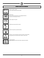
SYMBOLS USED ON THE MACHINE
Pad base lift-lower symbol
Used to indicate the base lift-lower switch
Brake symbol
Used to indicate the signal lamp of the engaged hand brake
Used above the emergency brake lever
Battery charge level symbol
Forward/reverse speed selector symbol
OFF/ 0
ON/ 1
Main switch symbol (key-operated switch)
Pad motor current consumption monitoring symbol (red signal lamp)
The signal lamp turns on when the brush motor is under strain
Open book symbol
Tells the worker to read the manual before operating the machine

22
SYMBOLS USED IN THE MANUAL
SYMBOLS USED IN THE MANUALSYMBOLS USED IN THE MANUAL
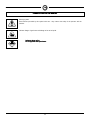
SYMBOLS USED IN THE MANUAL
Warning symbol
Read sections preceded by this symbol with care: they concern the safety of the operator and the
machine
Indicates danger of gas fumes and leakage of corrosive liquids
Indicates danger of fire
Indicates danger of fireIndicates danger of fire
Indicates danger of fire
Do not approach with open flames
Do not approach with open flamesDo not approach with open flames
Do not approach with open flames

23
PREPARING THE MACHINE
PREPARING THE MACHINEPREPARING THE MACHINE
PREPARING THE MACHINE
1.
1.1.
1.
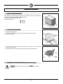
MOVING THE PACKAGED MACHINE
MOVING THE PACKAGED MACHINE MOVING THE PACKAGED MACHINE
MOVING THE PACKAGED MACHINE
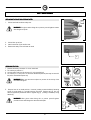
The machine is contained in specific packing with a platform so that it can be moved by
a fork-lift. More than two packings cannot be stacked.
Total weight is 180 kg (without batteries)
Packing dimensions are:
A:
A:A:
A: 1230 mm
B:
B:B:
B: 740 mm
C:
C:C:
C: 1490 mm
A
C
B
2.
2.2.
2.
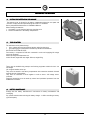
HOW TO UNPACK THE MACHINE
HOW TO UNPACK THE MACHINE HOW TO UNPACK THE MACHINE
HOW TO UNPACK THE MACHINE
1.
Remove the outer packing.
2.
The machine is fastened to its platform by wedges that clamp its wheels.
3.
Remove the wedges.
4. Use a ramp to lower the machine off the platform, pushing it in reverse. Avoid
violent blows to the base.
5.
Keep the platform since it may be necessary to transport the machine again.
3.
3.3.
3.
CONNECTING THE TRACTION MOTOR CABLE (machines with traction)
CONNECTING THE TRACTION MOTOR CABLE (machines with traction) CONNECTING THE TRACTION MOTOR CABLE (machines with traction)
CONNECTING THE TRACTION MOTOR CABLE (machines with traction)
WARNING!
WARNING!WARNING!
WARNING! This procedure must be done by a COMAC
COMACCOMAC
COMAC Service Center
technician.
R
R
R
R

24
PREPARING THE MACHINE
PREPARING THE MACHINEPREPARING THE MACHINE
PREPARING THE MACHINE
4.
4.4.
4.
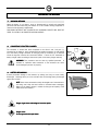
PUTTING THE BATTERIES IN THE MACHINE
PUTTING THE BATTERIES IN THE MACHINE PUTTING THE BATTERIES IN THE MACHINE
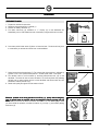
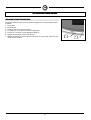
PUTTING THE BATTERIES IN THE MACHINE
The batteries must be housed in the battery compartment below the seat panel and
must also comply with the requirements given in CEI 21-5 standards.
Battery compartment dimensions are: 540x640 H480 mm.
When inserting the batteries:
1.
Use handle (1) to lift the hood and insert the safety strut
2.
Position the batteries in the battery compartment
5.
5.5.
5.
TYPE OF BATTERY
TYPE OF BATTERY TYPE OF BATTERY
TYPE OF BATTERY
The machine must be powered using:
• flat or tubular plate lead-acid traction batteries with free electrolyte;
• gel-technology gas recombination hermetically sealed traction batteries.
NO OTHER TYPES CAN BE USED.
Each battery is composed of DIN cells connected in series and supplying 6V voltage
across the terminals.
Maximum weight and dimensions are:
width 178 mm, length 295 mm, height 424 mm; weight 51kg
These must be handled using transport and hoisting equipment suitable for their size
and weight.
Lift using the handles on the top.
They must be housed in the battery compartment with connection terminals directed
towards the rear of the machine.
They must be connected in series together in order to have a 24V voltage across
terminals.
Electrical connections must be made by trained and specialized personnel from the
COMAC Service Center.
6.
6.6.
6.
BATTERY MAINTENANCE
BATTERY MAINTENANCE BATTERY MAINTENANCE
BATTERY MAINTENANCE
Comply with the battery manufacturer's instructions for battery maintenance and
recharging.
Pay special attention when selecting the battery charger: it differs according to battery
type and capacity.
1

25
PREPARING THE MACHINE
PREPARING THE MACHINEPREPARING THE MACHINE
PREPARING THE MACHINE
7.
7.7.
7.
DISPOSAL METHODS
DISPOSAL METHODS DISPOSAL METHODS
DISPOSAL METHODS
When the battery is run down it must be disconnected by trained and specialized
personnel and then lifted using the handles on it and suitable hoisting equipment to
remove it from the battery compartment.
RUN-DOWN BATTERIES ARE CLASSIFIED AS HAZARDOUS WASTE AND MUST BE
GIVEN TO A LEGALLY AUTHORIZED DISPOSAL AGENCY.
8.
8.8.
8.
CONNECTING THE BATTERY CHARGER
CONNECTING THE BATTERY CHARGER CONNECTING THE BATTERY CHARGER
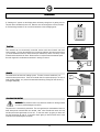
CONNECTING THE BATTERY CHARGER
The connector is located low down compared to the driver’s seat. Left part (1),
connected to the batteries, must be detached from machine connector (2) and hooked
up to the battery charger connector for charging. Hook-up connector (3) is delivered
inside the bag that contains this instruction booklet. It must be first connected to
battery charger cables according to instructions (refer to the battery charger manual).
WARNING!
WARNING!WARNING!
WARNING! This procedure must be done by qualified personnel. A
mistaken or imperfect cable connection to the connector can cause
severe damage to persons or property
9.
9.9.
9.
BATTERY RECHARGING
BATTERY RECHARGINGBATTERY RECHARGING
BATTERY RECHARGING
Prevent permanent damage to the batteries by making sure they are never totally
discharged. Recharge them just a few minutes after the flashing battery discharged
signal starts to flash.
NOTE
NOTENOTE
NOTE: Never leave the batteries totally discharged even if the machine is
not being used. Keep the hood raised as illustrated when recharging.
Make sure the battery charger is suitable for the type and capacity of the
batteries that are installed.
Danger of gas fumes and leakage of corrosive liquids.
Danger of gas fumes and leakage of corrosive liquids.Danger of gas fumes and leakage of corrosive liquids.
Danger of gas fumes and leakage of corrosive liquids.
Danger of fire.
Danger of fire.Danger of fire.
Danger of fire.
Do not approach with open flames
Do not approach with open flamesDo not approach with open flames
Do not approach with open flames
1
2
3

26
PREPARING THE MACHINE
PREPARING THE MACHINEPREPARING THE MACHINE
PREPARING THE MACHINE
10.
10.10.
10.
CONNECTING THE BATTERY CONNECTOR
CONNECTING THE BATTERY CONNECTOR CONNECTING THE BATTERY CONNECTOR
CONNECTING THE BATTERY CONNECTOR
Battery connector (1) must be connected to machine connector (2)
11.
11.11.
11.
BATTERY CHARGE LEVEL GAUGE
BATTERY CHARGE LEVEL GAUGE BATTERY CHARGE LEVEL GAUGE
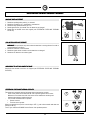
BATTERY CHARGE LEVEL GAUGE
The battery charge level gauge is a digital unit with 4 fixed and one flashing position.
The numbers on the display give an approximate idea of the state of charge:
4
4 4
4 = maximum charge, 3
33
3 = 3/4 charge, 2
22
2 = 2/4 charge, 1
11
1 = 1/4 charge, 0
00
0= batteries
discharged (flashing)
WARNING!
WARNING! WARNING!
WARNING! The brush motor automatically turns off a few seconds after
the flashing “0” appears. The remaining charge can be used to move the
machine to the recharging point.
12.
12.12.
12.
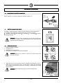
INSTALLING THE PAD
INSTALLING THE PAD INSTALLING THE PAD
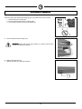
INSTALLING THE PAD
1.
Connect the battery connector
2.
Turn the key to "1"
3.
Operate the lever to lift the base
4.
Turn the key to "0" and pull it out from the dashboard
WARNING!
WARNING!WARNING!
WARNING! Make sure no persons or objects are in the vicinity of the
base when doing this.
3
1
2
4
5. Keep the base in its raised position. Unscrew (rotating counterclockwise) ring (1).
Install pad (2) on the disk drive plate. Use one hand to support the pad and the
other to tighten the fastening ring (rotating it clockwise), using handle (3) provided
with the machine.
WARNING!
WARNING! WARNING!
WARNING! Wear suitable safety gloves before installing the pad.
2
1
2
1
3

27
GENERAL SAFETY REGULATIONS
GENERAL SAFETY REGULATIONSGENERAL SAFETY REGULATIONS
GENERAL SAFETY REGULATIONS
Follow these regulations carefully to avoid harm to the operator and damage to the machine
Follow these regulations carefully to avoid harm to the operator and damage to the machineFollow these regulations carefully to avoid harm to the operator and damage to the machine
Follow these regulations carefully to avoid harm to the operator and damage to the machine.
r Read the labels on the machine carefully. Never cover them for any reason and immediately replace them if they are damaged
r
The machine must be used exclusively by authorized and trained personnel
r
When operating the machine be careful of other persons and of children in particular
r
Never mix different types of detergents: this could generate noxious gases
Never set containers of liquid on the machine
r
Machine storage temperature must be between -25°C and +55°C
Operating conditions: room temperature between 0°C and 40°C with relative humidity between 30 and 95%.
r
Never use the machine in an explosive environment
Never use the machine to transport goods
r
Never use acid solutions which could damage the machine and/or persons
Avoid running the brushes with the machine stopped: this could damage the floor
Never suck flammable liquids
Never use the appliance to collect dangerous powders.
r
Use a powder fire extinguisher in case of fire. Do not use water
r
Do not hit against shelving or scaffolding when there is a danger of falling objects
r
Suit operating speed to traction conditions
r
Do not use the appliance on surfaces with a slope higher than the one indicated on the name-plate.
Whenever you park the machine remove the key and apply the parking brake
Whenever the machine has operating troubles make sure these are not due to insufficient ordinary maintenance. If this is not
the case then enquire with your nearest
COMAC
COMACCOMAC
COMAC service center
r
When replacing machine parts always ask for ORIGINAL spare parts from your Authorized COMAC
COMACCOMAC
COMAC dealer and/or Retailer
r
Use only original COMAC
COMAC COMAC
COMAC polishing pads
Immediately engage the emergency lever in case of danger (connector placed below the machine operator)
Always cut off the electric power supply to the machine whenever maintenance is performed
r
Restore all electrical connections after terminating any maintenance procedures
Never remove guards that require tools for removal
r
Never wash the machine with direct or pressurized jets of water or with corrosive substances
r
Have your nearest COMAC
COMAC COMAC
COMAC service center check the machine every 200 operating hours
r
Before you use the machine make sure that all doors and covers are positioned as shown in this operating and maintenance
manual
r
Dispose of consumables in accordance with currently applicable laws and codes
r
When, after years of precious work, your COMAC
COMACCOMAC
COMAC machine is ready to be retired all of its component materials must be
properly disposed of: they contain oils, batteries and electronic components. Remember that the machine itself was built
using totally recyclable materials

28
OPERATION
OPERATIONOPERATION
OPERATION
PREPARING TO WORK
PREPARING TO WORKPREPARING TO WORK
PREPARING TO WORK
1.
Prepare the machine for operation
2.
Check that the parking brake is released (1)
3.
Connect the battery connector (2)
4.
Turn main switch key (3) clockwise to “1”. Display (4) on the dashboard will
immediately turn on and indicate the level of the battery charge and the hour counter.
2
3
4
6. Press base-pad lift-lower switch (5) down to lower the base. The brush will only start
to rotate when you actuate the control lever on the handlebar.
5
7. Select forward speed turning knob (7). The selector has three positions, indicated by
symbols: turtle = slow speed, middle position = normal speed, rabbit = fast speed
8.
The machine starts to move forward by actuating man-present lever (8) on the
handlebar. The base will start to lower and when it is all the way down the polishing
pad will start to rotate (release the lever on the handlebar and the base will lift a few
centimeters and the pad will stop)
9.
Check work quality during the first few meters of work.
Whenever problems arise during operation turn off key (1), quickly detach emergency
Whenever problems arise during operation turn off key (1), quickly detach emergencyWhenever problems arise during operation turn off key (1), quickly detach emergency
Whenever problems arise during operation turn off key (1), quickly detach emergency
lever (2) placed below the operator and set the emergency brake by pushing lever (3)
lever (2) placed below the operator and set the emergency brake by pushing lever (3)lever (2) placed below the operator and set the emergency brake by pushing lever (3)
lever (2) placed below the operator and set the emergency brake by pushing lever (3)
down.
down. down.
down. These procedures will block all machine movements. To start working again, after
you have solved the problem, reconnect connector (2), turn key (1) and release parking
brake lever (3).
2
3

29
OPERATION
OPERATIONOPERATION
OPERATION
A “flashing zero” appears on the display when the battery charge level is getting too low.
The pad motor automatically turns off. Batteries must be recharged as soon as possible.
A residual charge remains so as to move the machine to the recharging point.
TRACTION
TRACTIONTRACTION
TRACTION
This machine has an electronically controlled traction with three forward and three
reverse speeds. To move the machine first turn the key and then move man-present lever
(1) on the handlebar forward (to move forward) or backward (to move in reverse). Push it
forward and the machine will move. Rotate selector to adjust forward movement speed.
An audio signal will sound when the machine is moving in reverse.
BRAKES
BRAKESBRAKES
BRAKES
The machine has an electronic braking system. To brake, in normal conditions, just
release the man-present lever. If the service brake does not operate properly or in case of
need (parking, danger, etc.) actuate the mechanical brake by pushing the lever down (1)
(red signal lamp ON).
POLISHING PAD MOTOR
POLISHING PAD MOTORPOLISHING PAD MOTOR
POLISHING PAD MOTOR
WARNING!
WARNING!WARNING!
WARNING! The pad motor starts only when the machine is moving forward
in order to prevent damage to the floors.
The pad motor is electronically controlled. The red signal lamp on the dashboard starts to
flash when preset overload limits are reached. After a few seconds the motor will stop
and the pad switch signal lamp will turn off. To start the motor up again you must turn
the main switch key off and on. If the motor stops again you must find the cause of the
overload to prevent damage to the motor.
1
1
2

30
AFTER WORK IS TERMINATED
AFTER WORK IS TERMINATEDAFTER WORK IS TERMINATED
AFTER WORK IS TERMINATED
At the end of the work, before performing any type of maintenance proceed as follows
1.
Actuate switch (2) to lift the base
2.
Park the machine and actuate the parking brake
3.
Turn the key to position "0" to turn the machine off
5. Lift the hood and install the safety strut
WARNING!
WARNING! WARNING!
WARNING! Always wear gloves when doing this to protect yourself from
contact with hazardous solutions.
6. Replace disposable filter (7)
7.
Remove the safety strut and lower the hood
5
3
1
2

31
DAILY MAINTENANCE
DAILY MAINTENANCEDAILY MAINTENANCE
DAILY MAINTENANCE
REPLACING THE DUST COLLECTION FILTER
REPLACING THE DUST COLLECTION FILTERREPLACING THE DUST COLLECTION FILTER
REPLACING THE DUST COLLECTION FILTER
1.
Lift the hood and install the safety strut
WARNING!
WARNING! WARNING!
WARNING! Use gloves when doing this to protect yourself against contact
with dangerous liquids.
2. Lift the filter up and out
3.
Install a new filter (3) in the filter seat
4.
Remove the safety strut and lower the hood
REMOVING THE PAD
REMOVING THE PADREMOVING THE PAD
REMOVING THE PAD
1.
Connect the battery connector if it is not connected
2.
Turn the key to position “1”
3.
Use the control switch to lift the base (if it isn't already lifted)
4.
Turn the key to “0” and pull it out from the dashboard (hand injuries may be caused if
the pad is removed with power on)
WARNING!
WARNING!WARNING!
WARNING! Make sure there are no objects or persons in the vicinity of the
base when doing this.
3
1
2
4
5. Keep the base in its raised position. Unscrew (rotating counterclockwise) fastening
screw (2) using handle (1) provided with the drive disk. Replace pad (3). Use one
hand to support the pad and the other to tighten ring (2) (rotating it clockwise) using
handle (3).
WARNING!
WARNING! WARNING!
WARNING! Wear gloves when doing this to protect yourself against
possible contact with dangerous materials and liquids.
0
3
1
2
3
2

32
EXTRAORDINARY MAINTENANCE
EXTRAORDINARY MAINTENANCEEXTRAORDINARY MAINTENANCE
EXTRAORDINARY MAINTENANCE
REPLACING THE BASE SPLASHGUARDS
REPLACING THE BASE SPLASHGUARDSREPLACING THE BASE SPLASHGUARDS
REPLACING THE BASE SPLASHGUARDS
Periodically check the state of wear of the base splashguards. To replace them proceed
as follows:
1.
Lift the base
2.
Install the pad
3.
Lower the base until it touches the floor
4.
Turn the key to “0” and pull it out from the dashboard
5.
Loosen nut (1) and pull out the splashguard blade (2)
6.
Remove the splashguard rubber and replace it
7.
Reinstall everything by performing these procedures in reverse order. Make sure the
rubber touches the floor.
1
2

33
SOLUTION FOR THE MOST FREQUENT TROUBLES
SOLUTION FOR THE MOST FREQUENT TROUBLESSOLUTION FOR THE MOST FREQUENT TROUBLES
SOLUTION FOR THE MOST FREQUENT TROUBLES
MACHINE DOES NOT START
MACHINE DOES NOT STARTMACHINE DOES NOT START
MACHINE DOES NOT START
1.
Check that parking brake pedal (1) is released
2.
Check that connector (2) is connected to the batteries
3.
Check that key-operated switch (3) is on
4.
Check signal device (4) to make sure the batteries are charged
5.
Check that no thermal cutout has tripped (see ELECTRICAL FUSES AND THERMAL
CUTOUTS)
2
3
4
PAD MOTOR DOES NOT OPERATE
PAD MOTOR DOES NOT OPERATEPAD MOTOR DOES NOT OPERATE
PAD MOTOR DOES NOT OPERATE
WARNING!
WARNING!WARNING!
WARNING! The pad motor only starts when the machine is moving forward in order to
prevent damage to the floors
1.
Check that the base is lowered down
2.
Check the signal device to make sure the batteries are charged
3.
Check that no thermal cutout has tripped.
IMPOSSIBLE TO LIFT OR LOWER THE BASE
IMPOSSIBLE TO LIFT OR LOWER THE BASEIMPOSSIBLE TO LIFT OR LOWER THE BASE
IMPOSSIBLE TO LIFT OR LOWER THE BASE
Check that the thermal cutout has not tripped (see ELECTRICAL FUSES AND THERMAL
CUTOUTS)
ELECTRICAL FUSES AND THERMAL CUTOUTS
ELECTRICAL FUSES AND THERMAL CUTOUTSELECTRICAL FUSES AND THERMAL CUTOUTS
ELECTRICAL FUSES AND THERMAL CUTOUTS
The machine is equipped with the following electrical protection systems:
- Power fuses placed on the machine left side to protect against short-circuits.
Whenever a fuse blows check for the causes of the malfunction carefully and
eliminate them before replacing the fuse.
- Low-current resettable fuses to protect:
• General services
• Traction control system
When a resettable fuse trips first turn the key to OFF (1), wait a few seconds and then turn
the key to ON (2).
Turn to your authorized COMAC Service Center if the problem persists.
2
1

34
SELECTING AND USING POLISHING PADS
SELECTING AND USING POLISHING PADSSELECTING AND USING POLISHING PADS
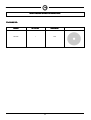
SELECTING AND USING POLISHING PADS
POLISHING PAD
POLISHING PADPOLISHING PAD
POLISHING PAD
Machine
MachineMachine
Machine No. of Pads
No. of PadsNo. of Pads
No. of Pads Pad diameter
Pad diameterPad diameter
Pad diameter
CM 50hs 1 508
-
 1
1
-
 2
2
-
 3
3
-
 4
4
-
 5
5
-
 6
6
-
 7
7
-
 8
8
-
 9
9
-
 10
10
-
 11
11
-
 12
12
-
 13
13
-
 14
14
-
 15
15
-
 16
16


Ask a question and I''ll find the answer in the document
Finding information in a document is now easier with AI
Related papers
-
COMAC CM 50 hs User manual
-
-
-
-
-
-
-
-
-
COMAC Abila 50B User manual


