1
© Copyright 2008 Printed
Before You Start
Your Floating Top Link is exclusively designed for your
Land Pride Quick Hitch. Please read these installation
instructions and your Quick Hitch Operator’s Manual
thoroughlybeforebeginning.Especiallyreadinformation
relating to safety concerns. Also included in the
Operator’sManualisimportantinformation onoperation,
adjustment, troubleshooting, and maintenance for this
attachment (some manual sections do not apply to all
accessories).
A separate Parts Manual for replacement parts can be
purchasedfrom yourdealer oravailable freeof charge at
www.landpride.com. Have model and serial numbers
handy when placing an order.
Manual Part Numbers:
• Operator’s Manual. . . . . . . . . . . . . . . . . 320-003M
• Parts Manual . . . . . . . . . . . . . . . . . . . . . 320-003P
General Information
These assembly instructions apply to the following
Floating Top Link Accessories listed below:
320-013A QH15 Floating Top Link Assembly
320-028A QH20 Floating Top Link Assembly
!
DANGER!
Engage parking brake, shut tractor engine off and remove
switch key before performing installation of the Floating Top
Link.
When you see this symbol, the subsequent
instructions and warnings are serious - follow
without exception. Your life and the lives of
others depend on it!
!
IMPORTANT: Before you begin, read these
instructions and check to be sure all parts and tools
are accounted for. Please retain these installation
instructions for future reference and parts ordering
information.
The Floating Top Link Kits are designed to adapt the
Category l & ll Quick-Hitches to implements that need to
float about the upper hitch and lower hitch points during
operation. Implements with gauge wheel(s) usually
require a Floating Top Link. These kits are designed to
adapt to the following Land Pride products:
Category ll Floating Top Link
• Rotary Cutters:
Series RCR1884, RCR2596, RCR2510, RCRM2510 &
RCR26
Category l Floating Top Link
• Flat Deck Grooming Mowers:
Series FD15, FDR15, FDR1660, FDR1672, FD25,
FDR25 and FDR3590 after S/N 294658
• Air Tunnel Grooming Mowers:
Series AT25, AT26 & AT35
• Rotary Cutters:
Series RC15, RCR15, RCR16, RCR18, RCR2560,
RCR2596, RCR2572, RCR2660 & RCR2672
• Power Rake:
Series PR16, PR25
• Seeders:
Series OS15 w/front roller, PS15 & APS15
Further Assistance
Your dealer wants you to be satisfied with your new
Floating Top Link. If for any reason you do not
understand any part of this manual or are not satisfied
with the service received, the following actions are
suggested:
1. Discuss the matter with your dealership service
manager making sure he is aware of any problems
youmayhaveand that he has had the opportunity to
assist you.
2. If you are still not satisfied, seek out the owner or
general manager of the dealership, explain the
problem and request assistance.
3. For further assistance write to:
Land Pride Service Department
1525 East North Street
P.O. Box 5060
Salina, Ks. 67402-5060
E-mail address
lpser[email protected]
Cat. l & Cat. ll Quick Hitches
Floating Top Link
Assembly Instructions
5/18/10
Manual No. 320-014M

2
Manual No. 320-014M 5/18/10
QH15 Floating Top Link Installation
■
QH15 Floating Top Link
Installation
Refer to Figure 1:
Below is a detailed listing of parts included in this kit to
serve as a checklist to inventory parts received. Please
contact your local Land Pride dealer for any missing
hardware.
1. Remove existing 3/4" x 3 1/2" clevis pin (#5) and hair
pin cotter (#6).
2. Install floating link bars (#2) with new 3/4" x 3 3/4"
clevispin(#1A)andhairpin cotter (#4A)makingsure
the four washer (#3) goes to the same side as the
nuts (noted with larger arrow) in Figure 1.
3. Assemble spacer (#7) in implement’s top link and
place implement’s top link between links (#2) as
shown. Secure with clevis pin (#1B) and hair pin
cotter (#4B).
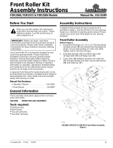
QH15 Floating Top Link Installation
Figure 1
QH15 Floating Top link Components
320-013A QH15 Floating Top Link Assembly Kit
Qty Part No. Part Description
1 701-014M ASSEMBLY INSTRUCTIONS
2 805-228C PIN CLEVIS 3/4 X 3 3/4 PLT
2 320-034D QH FLOATING TOP LINK BAR
4 804-024C WASHER FLAT 3/4 USS PLT
2 805-143C PIN HAIR COTTER .120 PLT
1 320-035D FLT TOP SPCER 1.12 O.D. x .81 I.D. x1 15/16”
IMPORTANT: If the Floating Top Link is being
assembledon units with Serial Numbers 269719 and
below then the bolts, nuts and lock washers
(indicated with the arrow) should be replaced with
bolt 802-128C and locknut 803-019C. This is due to
the existing bolts being too long.
18116
IMPLEMENT TOP LINK (NOT
INCLUDED WITH QUICK-HITCH
FLOATING TOP LINK KIT)
See Assembly
Instructions
Important Note
QH20 Floating Top Link
Installation
Refer to Figure 2:
Below is a detailed listing of parts included in this kit to
serve as a checklist to inventory parts received. Please
contact your local Land Pride dealer for any missing
hardware.
1. Removeexisting 1” x 31/2” clevispin(#4)and hairpin
cotter (#6).
2. Install floating link bars (#2) and flat washers (#3)
with 1” x 4 1/2” clevis pin (#5A) and hair pin cotter
(#6) as shown.
3. Assemble implement’s top link (#1) between floating
link bars (#2) as shown. Insert clevis pin (#5B) and
secure with hair pin cotter (#6).
QH20 Floating Top Link Installation
Figure 2
QH20 Floating Top link Components
320-028A QH20 Floating Top Link Assembly Kit
Qty Part No. Part Description
1 701-014M ASSEMBLY INSTRUCTIONS
2 320-067D QH FLOATING TOP LINK CAT II
2 804-028C WASHER FLAT 1 USS PLT
2 805-131C PIN CLEVIS 1 X 4 11/16 USABLE
2 805-032C PIN HAIR COTTER .148 WIRE
24878
IMPLEMENT TOP LINK (NOT
INCLUDED WITH QUICK-HITCH
FLOATING TOP LINK KIT)

3
5/18/10
Manual No. 320-014M
QH20 Floating Top Link Installation
■
Floating Top Link Positioning
Operating Position
Refer to Figure 3:
1. Park tractor and implement on level ground.
2. Adjust rear gauge wheel(s) to the correct working
height.
3. Lower implement with tractor’s 3-point lift until the
front is at the correct working height. Rear gauge
wheel(s) should be on the ground supporting the
implement’s rear end. If not, lengthen tractor’s
3-point top center link until the rear end is supported
by the gauge wheel(s).
4. With implement set at the correct working height,
adjust 3-pointtop center link until the floating toptwo
links dip halfway down into the upper hook as shown.
Floating Top Link Position When
Tail Wheel & Skid Shoes Are On The Ground
Figure 3
NOTE: Refer to implement’s operating manual for a
complete description on how to set the implement to
the correct working height.
22159
Implement Top Link
Floating Top Link Kit
3-Point Top
Center Link
Transporting Position
Refer to Figure 4:
The floating top links should be straight as shown when
implement’s gauge wheel(s) are raised off the ground.
Floating Top Link Position When
Tail Wheel & Skid Shoes Are Off The Ground
Figure 4
22141
Implement Top Link
Floating Top Link Kit

Corporate Office: P.O. Box 5060
Salina, Kansas 67402-5060 USA
www.landpride.com
/