Page is loading ...

A-1
Thank you for choosing the Mitsubishi transistorized inverter option unit.
This instruction manual gives handling information and precautions for use of this equipment. Incorrect handling
might cause an unexpected fault. Before using the equipment, please read this manual carefully to use the equipment
to its optimum.
Please forward this manual to the end user.
1. Electric Shock Prevention
This section is specifically about safety matters
Do not attempt to install, operate, maintain or inspect this product until you have read through this instruction
manual and appended documents carefully and can use the equipment correctly. Do not use this product until you
have a full knowledge of the equipment, safety information and instructions.
In this instruction manual, the safety instruction levels are classified into "WARNING" and "CAUTION".
Assumes that incorrect handling may cause hazardous conditions, resulting in
death or severe injury.
Assumes that incorrect handling may cause hazardous conditions, resulting in
medium or slight injury, or may cause physical damage only.
Note that the level may lead to a serious consequence according to conditions. Please follow the
instructions of both levels because they are important to personnel safety.
SAFETY INSTRUCTIONS
!
While power is on or when the inverter is running, do not open the front cover. You may get an electric shock.
!
Do not run the inverter with the front cover removed. Otherwise, you may access the exposed high-voltage
terminals and charging part and get an electric shock.
!
Even if power is off, do not remove the front cover except for wiring or periodic inspection. You may access the
charged inverter circuits and get an electric shock.
!
Before starting wiring or inspection, check to make sure that the inverter power indicator lamp is off, wait for at
least 10 minutes after the power supply has been switched off, and check that there are no residual voltage using
a tester or the like..
WARNING
CAUTION
CAUTION
WARNING

A-2
2. Injury Prevention
3. Additional Instructions
Also note the following points to prevent an accidental failure, injury, electric shock, etc.:
(1) Transportation and mounting
(2) Test operation and adjustment
!
Any person who is involved in the wiring or inspection of this equipment should be fully competent to do the work.
!
Always install the option unit before wiring. Otherwise, you may get an electric shock or be injured.
!
Handle this option unit with dry hands to prevent an electric shock.
!
Do not subject the cables to scratches, excessive stress, heavy loads or pinching. Otherwise, you may get an electric shock.
!
While power is on, do not move the station number and baud rate setting switches. Doing so can cause an electric shock.
!
Apply only the voltage specified in the instruction manual to each terminal to prevent burst, damage, etc.
!
Ensure that the cables are connected to the correct terminals. Otherwise, burst, damage, etc. may occur.
!
Always make sure that polarity is correct to prevent burst, damage, etc.
!
While power is on or for some time after power-off, do not touch the inverter as it is hot and you may get burnt.
!
Do not install or operate the option unit if it is damaged or has parts missing.
!
Do not stand or rest heavy objects on the product.
!
Check that the mounting orientation is correct.
!
Prevent screws, metal fragments or other conductive bodies or oil or other flammable substance from entering the inverter.
!
Before starting operation, confirm and adjust the parameters. A failure to do so may cause some machines to
make unexpected motions.
WARNING
CAUTION
CAUTION
CAUTION
A-3
(3) Usage
(4) Maintenance, inspection and parts replacement
(5) Disposal
(6) General instruction
!
Do not modify the equipment.
!
When parameter clear or all parameter clear is performed, each parameter returns to the factory setting. Reset
the required parameters before starting operation.
!
For prevention of damage due to static electricity, touch nearby metal before touching this product to eliminate
static electricity from your body.
!
Do not test the equipment with a megger (measure insulation resistance).
!
Treat as industrial waste.
All illustrations given in this manual may have been drawn with covers or safety guards removed to provide indepth
description. Before starting operation of the product, always return the covers and guards into original positions as
specified and operate the equipment in accordance with the manual.
WARNING
CAUTION
CAUTION
CAUTION

CONTENTS
1.PRE-OPERATION INSTRUCTIONS 1
1.1 Unpacking and Product Confirmation..................................................................................................1
1.2 Packing Confirmation...........................................................................................................................1
1.3 Instruction Manual Note.......................................................................................................................2
1.4 Structure ..............................................................................................................................................2
1.5 Inverter Option (FR-A5NC) Specifications...........................................................................................4
1.6 CC-Link Ver. 1.10 ................................................................................................................................5
2.INSTALLATION 6
2.1 Pre-Installation Instructions..................................................................................................................6
2.2 Station Number and Transmission Baud Rate Setting ........................................................................6
2.2.1 Station number setting..................................................................................................................6
2.2.2 Setting of the transmission baud rate setting switch.....................................................................8
2.3 Installation Procedure.........................................................................................................................8
3.Wiring 11
3.1 System Configuration Example..........................................................................................................11
3.2 Connection Cable ..............................................................................................................................12
3.3 Connection Diagram..........................................................................................................................12
3.4 Connection of Several Inverters.........................................................................................................13
4. INVERTER SETTING 14
4.1 Parameter List....................................................................................................................................14

4.2 Operation Mode.................................................................................................................................16
4.2.1 Operation mode indication.........................................................................................................16
4.2.2 Operation mode switching ..........................................................................................................17
4.3 Operation and Speed Command Source...........................................................................................26
4.3.1 FR-A500(L)/F500(L) series.........................................................................................................26
4.3.2 FR-V500 series...........................................................................................................................30
4.4 Operation at Communication Error Occurrence.................................................................................33
4.4.1 Operation selection at communication error occurrence ............................................................33
4.4.2 Alarm and measures...................................................................................................................37
4.5 Inverter reset......................................................................................................................................38
5. FUNCTION OVERVIEW 40
5.1 Function Block Diagram.....................................................................................................................40
5.2 Function Overview.............................................................................................................................41
5.2.1 Output from the inverter to the PLC............................................................................................42
5.2.2 Input to the inverter from the PLC...............................................................................................43
5.3 Device No. .........................................................................................................................................45
6. COMMUNICATION SPECIFICATIONS—A500(L)/F500(L) series 46
6.1 I/O Signal List.....................................................................................................................................46
6.1.1 Output signals (master unit to inverter (FR-A5NC))....................................................................46
6.1.2 Input signals (inverter (FR-A5NC) to master unit).......................................................................49
6.2 Remote Register Assignment............................................................................................................51
6.2.1 Remote registers (master unit to inverter (FR-A5NC)) ...............................................................51
6.2.2 Remote registers (inverter (FR-A5NC) to master unit) ...............................................................52
6.3 Instruction Codes...............................................................................................................................53
6.4 Code Definitions.................................................................................................................................55

6.4.1 Reply Code.................................................................................................................................55
6.4.2 Monitor codes .............................................................................................................................56
6.4.3 Error code...................................................................................................................................58
7. COMMUNICATION SPECIFICATIONS —V500 series 59
7.1 I/O Signal List.....................................................................................................................................59
7.1.1 Output signals (master unit to inverter (FR-A5NC))....................................................................59
7.1.2 Input signals (inverter (FR-A5NC) to master unit).......................................................................62
7.2 Remote Register Assignment............................................................................................................64
7.2.1 Remote registers (master unit to inverter (FR-A5NC)) ...............................................................64
7.2.2 Remote registers (inverter (FR-A5NC) to master unit) ...............................................................65
7.3 Instruction Codes...............................................................................................................................66
7.4 Code Definitions.................................................................................................................................69
7.4.1 Reply Code.................................................................................................................................69
7.4.2 Monitor codes .............................................................................................................................70
7.4.3 Error code...................................................................................................................................72
7.5 Torque command from communication (Torque control)...................................................................73
8. PROGRAMMING EXAMPLES 75
8.1 Program Example for Reading the Inverter Status............................................................................76
8.2 Program Example for Setting the Operation Mode............................................................................78
8.3 Program Example for Setting the Operation Commands...................................................................79
8.4 Program Example for Monitoring the Output Frequency ...................................................................81
8.5 Parameter Reading Program Example..............................................................................................82
8.6 Parameter Writing Program Example................................................................................................83
8.7 Running Frequency (Running Speed) Setting Program Example .....................................................84
8.8 Alarm Definition Reading Program Example .....................................................................................86

8.9 Program Example for Resetting the Inverter at Inverter Error ...........................................................87
8.10 Instructions.........................................................................................................................................88
9. HOW TO CHECK FOR ERROR USING THE LEDS 90
9.1 When One Inverter Is Connected ......................................................................................................90
9.2 When Two or More Inverters Are Connected ....................................................................................92
9.3 Communication Stops During Operation ...........................................................................................94

1
1.PRE-OPERATION INSTRUCTIONS
1.1 Unpacking and Product Confirmation
Take the option unit out of the package, check the unit name, and confirm that the product is as you ordered and
intact.
Note that the FR-A500(L)/F500(L) series inverter and FR-V500 series inverter have different functions
when the option is fitted.
Please check the SERIAL number of the inverter.
SERIAL number check
• This product may be used with the FR-A500 series manufactured in and after November 1997. Any of the
models may be used with this unit if its SER
IAL number indicated on the rating plate and package has
"R7Y""""""" or later version.
• This product may be used with the FR-V500 series manufactured in and after March 2002. Any of the
models may be used with this unit if its SERIAL number indicated on the rating plate and package has
""23""""""" or later version. For details of the SERIAL number, please contact your sales
representative.
SERIAL is made up of 1 version symbol, 1 alphabet letter or numeric character indicating month, and 7
numeric characters indicating the year and control number as shown below. (Only the first three digits
of the control number are printed on the package.)
SERIAL number
1.2 Packing Confirmation
Make sure that the package includes the following
• Instruction manual...........................................................................1
• Mounting screws M3 × 6 .................................................................2
"
2 3 """"""
Symbol Year Month Control number

2
PRE-OPERATION INSTRUCTIONS
1.3 Instruction Manual Note
(1) Refer to the following manuals for full information on the CC-Link master station:
• AJ61BT11/A1SJ61BT11 Control & Communication Link system master/local module user's manual..............IB-66721
• AJ61QBT11/A1SJ61QBT11 Control & Communication Link system master/local module user's manual........IB-66722
• QJ61BT11 Control & Communication Link system master/local module user's manual.................................SH-080016
(2) In this manual, Control & Communication Link is abbreviated to CC-Link.
1.4 Structure
STATION NO.
FR-A5NC
NC DB DG
DA SLD
RUN
L.RUN
SD
SR
L.ERR
B.RATE
10
´
1
(FG)
0
9
8
7
6
5
4
3
2
1
0
9
8
7
6
5
4
3
2
1
0
9
8
7
6
5
4
3
2
1
Mounting
hole
Terminal
block
screw size M3
Front view
Terminal block
mounting/
dismounting screw
Transmission
baud rate
setting switch
Station number
setting switches
Terminal block mounting/
dismounting screw
Mounting
holes
Option fixing holes
Rear view
Connector
Mounting
hole
Operating
status
indicator
LEDs
SERIAL
SERIAL
Products
supporting CC-Link
Ver.1.10 has a logo.
3
PRE-OPERATION INSTRUCTIONS
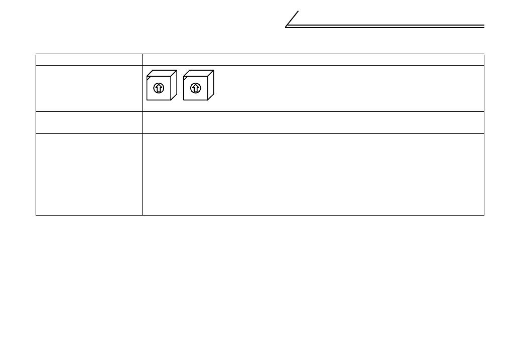
(1) Names and functions
Name Function
Station number setting
switches
Used to set the inverter station number between 1 and 64.
For details, refer to page 6.
Transmission baud rate
setting switch
Used to set the transmission speed.
For details, refer to page 8.
Operating status indicator
LEDs
RUN............ Lit during normal operation (when internal 5V is normal). (Also lit when
communication is not yet started.)
L.RUN......... Lit to indicate that refresh data is received properly. Extinguished to indicate
a break in data for a given period of time.
SD............... Extinguished to indicate that send data is "0".
RD............... Lit to indicate that the carrier of receive data is detected.
L.ERR.........Lit to indicate the communication error of the station itself. Flickers to
indicate that the switch or other setting was changed while power is on.
×
10
0
9
8
7
6
5
4
3
2
1
×
1
0
9
8
7
6
5
4
3
2
1

4
PRE-OPERATION INSTRUCTIONS
1.5 Inverter Option (FR-A5NC) Specifications
Type
Inverter inboard option fitted to the terminal block(can be mounted/dismounted to/from
the inverter front face)
Power supply 5VDC supplied from the inverter
Number of units connected 42 units max. (1 station occupied by 1 unit). May be used with other equipment.
Terminal block
8-pin terminal block (M3
× 6 screws)
Cable size
0.75mm
2
to 2mm
2
Station type Remote device station
Number of stations occupied One inverter occupies one station.
Communication cable CC-Link dedicated cable, CC-Link Version 1.10 compatible CC-Link dedicated cable
REMARKS
When the CC-Link unit (FR-A5NC) is plugged in, the protective structure (JEM1030) is open type (IP00).
5
PRE-OPERATION INSTRUCTIONS
1.6 CC-Link Ver. 1.10
The conventional CC-Link products, whose inter-station cable lengths have equally been changed to 20cm
(7.87 inch) or more to improve the inter-station cable length restriction, are defined as CC-Link Ver. 1.10. In
comparison, the conventional products are defined as CC-Link Ver. 1.00.
Refer to the CC-Link Master Module Manual for the maximum overall cable lengths and inter-station cable
lengths of CC-Link Ver. 1.00 and Ver. 1.10.
(1) CC-Link Ver. 1.10 compatibility conditions
1) All modules that comprise a CC-Link system should be compatible with CC-Link Ver. 1.10.
2) All data link cables should be CC-Link Ver. 1.10 compatible, CC-Link dedicated cables. (CC-Link
Ver. 1.10 compatible cables have a logo or Ver. 1.10 indication.)
(2) How to confirm the CC-Link Ver. 1.10 compatible products
Only the FR-A5NC units manufactured in and after September 2001 are CC-Link Ver. 1.10 compatible.
1) Product having SERIAL number of "F19 " or later version on its board and package
(Only the first three digits of the control number are printed on the package.)
2) Product having a logo on its board
Refer to page 2 for the SERIAL and logo positions on the board.
CAUTION
In a system that uses the CC-Link Ver. 1.00 and Ver. 1.10 modules and cables together, the
maximum overall cable length and inter-station cable length are as specified for CC-Link Ver. 1.00.
F
Symbol
SERIAL number
Year Month Control number
1 9
6
2.INSTALLATION
2.1 Pre-Installation Instructions
Make sure that the input power of the inverter is off.
2.2 Station Number and Transmission Baud Rate Setting
2.2.1 Station number setting
Set the inverter station number before switching on the inverter and do not change the setting while power
is on.
The station number may be set between 1 and 64.
With input power on, do not install or remove the option unit. Otherwise, the inverter and
option unit may be damaged.
CAUTION
1. The station number changed while powering on the inverter is not made valid. The station
number setting is made valid either after power is reapplied or when the RES signal turns on.
2. Note that the same station number cannot be reqeated. (If the same station number is
repeated, proper communication cannot be made.)
CAUTION
7
INSTALLATION
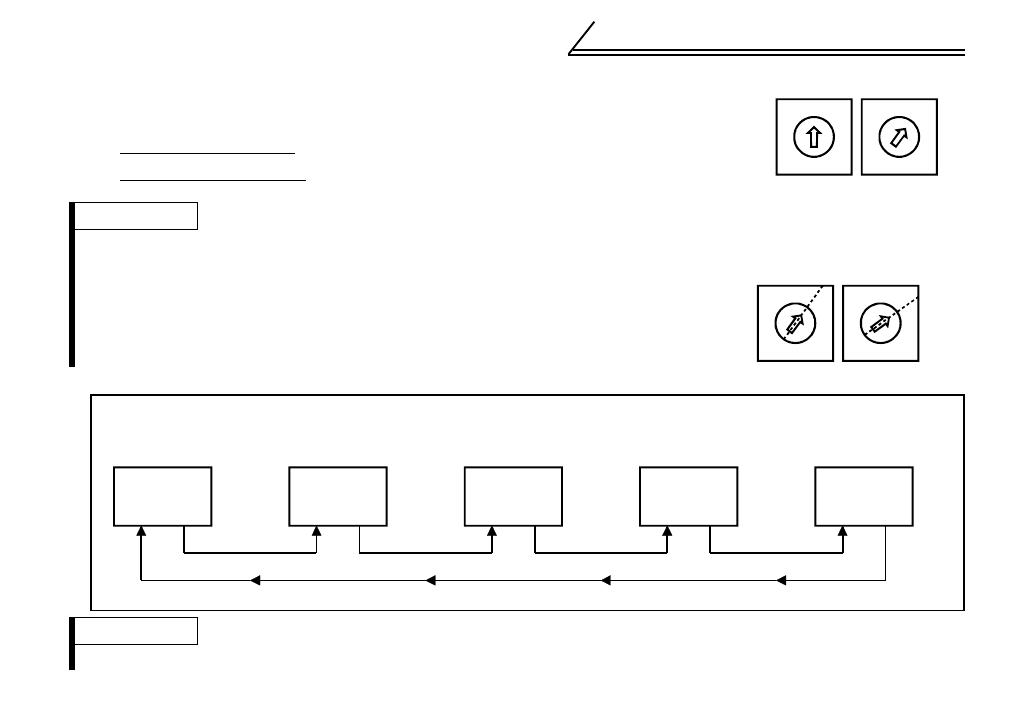
3)Connection example
!Set the arrow (#) of the corresponding switch to the required numeral.
Example:
• For station number 1
: Set (#) of
×
10 to "0" and (#) of
×
1 to "1".
• For station number 26
: Set the (#)
×
10 to "2" and the (#)
×
1 to "6".
REMARKS
• Set station numbers consecutively in a connection sequence.
(The station numbers may also be set independently of the connection sequence.)
• Set each station number switch to the position of its numeral without error. If it is set
to any position between numerals, normal data communication cannot be made.
REMARKS
One inverter occupies one station (one remote device station)
tation number setting switches
0
9
8
7
6
5
4
3
2
1
0
9
8
7
6
5
4
3
2
1
×
10
×
1
G
ood example
0
9
8
7
6
5
4
3
2
1
0
9
8
7
6
5
4
3
2
1
Bad example
CC-Link
master unit
PLC remote I/O station
(1 station occupied)
Inverter 1
(CC-Link unit)
Remote device station
Inverter 2
(CC-Link unit)
Remote device station
Inverter 3
(CC-Link unit)
Remote device station
Station 02Station 01 Station 03 Station 04
Number of units connected is 4.
Station 00
8
INSTALLATION
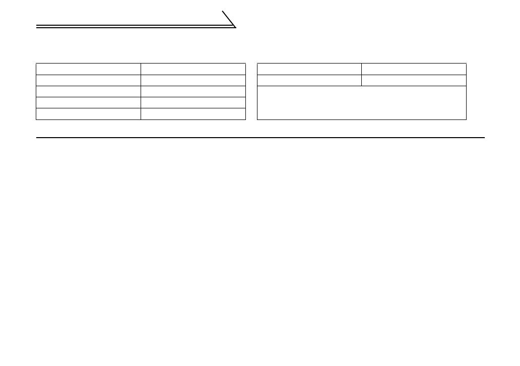
2.2.2 Setting of the transmission baud rate setting switch
Set the transmission speed. (For details, refer to the CC-Link master unit manual.)
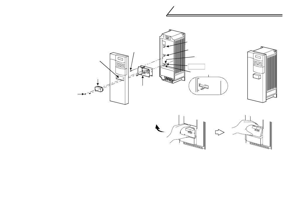
2.3 Installation Procedure
(1) Mount the option unit to slot 3.
Remove the DATA PORT from the front cover and mount the front cover. (To remove the DATA PORT
cover, push it from the back of the front cover.) (If it is fitted in slot 1 or 2, E.OP1 (E.OP2) is displayed
and the inverter will not function.)
(2) Securely insert the connector of the option unit far into the connector of slot 3 in the inverter. At this
time, fit the option fixing holes snugly. For the position of slot 3, refer to the next page. Also be sure to
fit the unit into the option fixing hook (For the FR-A500(L)/ FR-F500(L) series, it is available in Aug.,
2000).
(3) Securely fix the two right and left places of the option unit to the inverter with the accessory mounting
screws. If the screw holes do not line up, the connector may not have been plugged snugly. Check for
looseness.
(4) Remove the terminal block mounting/dismounting screws to dismount the terminal block.
(5) Reinstall the front cover of the inverter. (Refer to the inverter manual.)
(6) Reinstall the terminal block securely.
Setting Switch Transmission Speed Setting Switch Transmission Speed
0 156kbps 4 10Mbps
1 625kbps
5 or later should not be used.
(If the switch is set to position 5 or later, the "L.ERR"
LED is lit and a communication error occurs.)
22.5Mbps
35Mbps
9
INSTALLATION
(7) To remove the option unit, remove the two left and
right screws, and then hold the option unit and pull
its bottom toward you as shown in the figure. (The
option unit is fixed by the hook of the inverter.)
DATA PORT
Accessory screw
(2 pcs.)
CC-Link unit
(FR-A5NC)
Terminal block
ote: The mounting screws
do not release from
terminal block.
Slot 1
Slot 2
Inverter side
connector
Slot 3
Inverter
(Without cover)
Inverter
(With cover)
Option fixing hook
The slots 1, 2, and 3 are provided
with an option fixing hook.
10
INSTALLATION
REMARKS
1. Before wiring, mount the option unit (FR-A5NC) and fit the inverter front cover.
2. After wiring, wire offcuts must not be left in the inverter. They may cause a fault, failure or malfunction.
3. The option unit (FR-A5NC) can be used only when mounted in the slot 3.
4. When two or more communication options are mounted, "E.OPT" error is displayed. Note that the error will not be
displayed and relay output and FR-A5NC will activate when used with the relay output/computer link unit (FR-
A5NC).
5. When installing the inverter front cover with the terminal block attached, the front cover may not be fitted properly.
When installing the inverter front cover, the cables to the inverter's control circuit terminals
and option terminals should be routed properly in the wiring space to prevent them from
being caught between the inverter and its cover.
CAUTION
11
3.Wiring
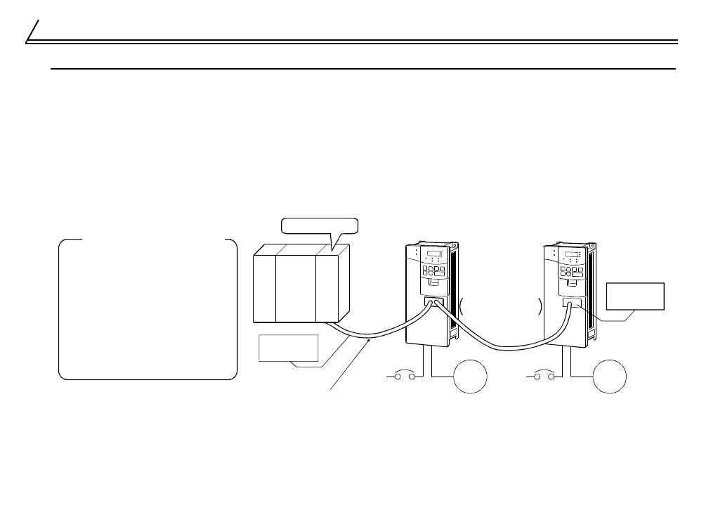
3.1 System Configuration Example
(1) PLC side
Load the "AJ61BT11", "A1SJ61BT11", "AJ61QBT11", "A1SJ61QBT11" or "QJ61BT11" "Control &
Communication Link system master/local module" on the main or extension base unit having the PLC
CPU used as the master station.
(2) Inverter side
Mount the "CC-Link unit (FR-A5NC)" on the inverter. Before wiring, mount the CC-Link unit (FR-A5NC)
and fit the inverter front cover.
(3) Connect the PLC CC-Link unit master station and the FR-A5NC with the CC-Link dedicated cable.
(4) When the CPU has automatic refresh function (example: QnA series CPU)
Through communication with the corresponding devices using sequence ladder logic, data is
automatically transferred to the refresh buffer of the master station at the execution of the END
instruction to perform communication with the remote devices.
CC-Link dedicated cable
Inverter
Power
supply
Motor
Motor
Inverter
Manuals for CC-Link master station
AJ61BT11/A1SJ61BT11 Control &
Communication Link system master/local
module user's manual
... IB-66721
AJ61QBT11/A1SJ61QBT11 Control &
Communication Link system master/local
module user's manual
... IB-66722
QJ61BT11 Control & Communication Link
system master/local module user's manual
... SH-080016
Termination
resistor
Termination
resistor
Up to 42 units
may be connected
when only inverters
are connected
Power
supply
Power supply
module
CPU AJ61
BT11
Master station
12
Wiring
(5) When the CPU does not have automatic refresh function (example: AnA series CPU)
Data is transferred to the refresh buffer of the master station directly by sequence ladder logic to
perform communication with the remote devices.
3.2 Connection Cable
If the cable used is other than the CC-Link dedicated cable, the performance of the CC-Link system is not
guaranteed.
For the specifications and availability of the CC-Link dedicated cable, refer to the CC-Link catalog.
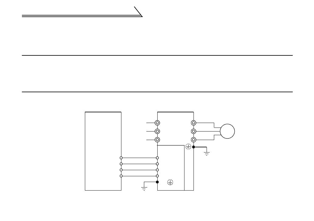
3.3 Connection Diagram
The following diagram shows how to wire the inverter and PLC CC-Link master unit:
U
V
W
R
S
T
DA
DB
DG
SLD
FG
DA
DB
DG
SLD
P
LC CC-Link master unit
Power
supply
Inverter
Motor
FR-A5NC
/