Kozyheat Two Harbors Owner's manual
- Category
- Fireplaces
- Type
- Owner's manual

Report No. 216-F-08-5
www.kozyheat.com
MAY 2013
TWO-REV-06
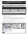
DIRECT VENT GAS FIREPLACE
INSTALLATION MANUAL
—Do not store or use gasoline or other flammable vapors and liquids in the vicinity
of this or any other appliance.
WHAT TO DO IF YOU SMELL GAS:
◙ Do not try to light any appliance.
◙ Do not touch any electrical switch: do not use any phone in your building.
◙ Immediately call gas supplier from a neighbor’s phone. Follow the gas supplier’s
instructions.
◙ If you cannot reach your gas supplier, call the fire department.
—Installation and service must be performed by a qualified installer, service agency
or the gas supplier.
WARNING: If the information in these instructions is not followed exactly, a fire
or explosion may result causing property damage, personal injury or loss of life.
This appliance may be installed in an aftermarket permanently located,
manufactured home (USA only) or mobile home, where not prohibited by local codes.
This appliance is only for use with the type of gas indicated on the rating plate. This
appliance is not convertible for use with other gases, unless a certified kit is used.
INSTALLER: Leave this manual with the appliance.
CONSUMER: Retain this manual for future reference.
IMPORTANT: This installation manual is to be used in conjunction with SUPPLEMENTAL
INSTALLATION AND HOMEOWNER INFORMATION MANUAL. Read both manuals before installing
and operating appliance.
English and French Installation Manuals Available Through Your Local Dealer or Visit Our Website at www.kozyheat.com
Les manuels d’installation en anglais et en français sont disponibles chez votre détaillant local ou en visitant notre site Web : www.kozyheat.com
WARNING
HOT GLASS WILL CAUSE BURNS.
DO NOT TOUCH GLASS UNTIL COOLED.
NEVER ALLOW CHILDREN TO TOUCH GLASS.

CONGRATULATIONS!
We welcome you as a new owner of a Kozy Heat gas fireplace. Kozy Heat products are
designed with superior components and materials, assembled by trained craftsmen who take
pride in their work. The burner and valve assembly are 100% test-fired and the complete fire-
place is thoroughly inspected before packaging to ensure that you receive a quality product.
Our commitment to quality and customer satisfaction has remained the same for over 30 years.
We offer a complete line of gas and wood fireplaces, unique cabinets and stylish accessories to
complement any décor. Adding a fireplace is one of the best ways to increase the value of your
home, and we are proud to offer a network of dealers throughout the country to help make
your experience everything you imagine. We pride ourselves in being dedicated to not only
functionality and reliability, but also customer safety. We offer our continual support and
guidance to help you achieve the maximum benefit and enjoyment from your Kozy Heat gas
fireplace.
Jim Hussong Dudley Hussong
President Board Chairman
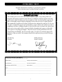
INTRODUCTION
Read this manual before installing or operating this appliance.
Please retain this owner’s manual for future reference.
Homeowner Reference Information
We recommend that you record the following information about your fireplace.
Model Name:______________________________ Date purchased/installed:___________________________
Serial Number:____________________________ Location on fireplace:_______________________________
Dealership purchased from:__________________ Dealer Phone:____________________________________
Notes:_____________________________________________________________________________________
__________________________________________________________________________________________
__________________________________________________________________________________________
1

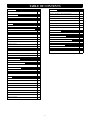
TABLE OF CONTENTS
INTRODUCTION
Introduction and Homeowner Reference Information 1
TABLE OF CONTENTS
Table of Contents 2
SAFETY INFORMATION
Safety Information 3
FEATURES
Features 4
COMMONWEALTH OF MASSACHUSETTS INFORMATION
Commonwealth of Massachusetts Information 5
SPECIFICATIONS
Fireplace Dimensions 6
Clearances 6
Components List 7
Additional Components Required 7
Installation Overview 7
Placement Clearance Requirements 7
FRAMING
Wall Enclosure Rough Opening 8
Vertical Terminations 9
Horizontal Terminations 9
MANTEL REQUIREMENTS
Mantel Requirements 10
TYPICAL INSTALLATION OPTIONS
Typical Installation Options 10
GLASS FRAME ASSEMBLY
Glass Frame Assembly Removal / Installation 11
GAS LINE CONNECTION
Gas Line Connection 12
VENTING
Approved Venting 13
Horizontal Vent System Clearances 13
Min. / Max. Horizontal Vent System Information 13
Vertical Vent System Clearances 13
Min. / Max. Vertical Vent System Information 13
Horizontal / Vertical Combination Venting 13
Elbows 14
Restrictor Installation 14
Securing Vent System 14
2
VENTING (cont.)
Horizontal Vent Shield Installation 15
#800-WPT / #800-WPT-2 Wall Pass-thru Installation 15
Horizontal Venting Illustrations 16
Exhaust Damper Position (LP Gas Horizontal Vent Configuration) 16
Vertical Venting Illustration 17
Horizontal / Vertical Venting Illustration 17
Termination Vent Cap Location 18
Vertical Cap Requirements 19
LOG SET INSTALLATION
Log Set Installation 20
FULL DOOR FACE INSTALLATION
Full Door Face Installation 21
CONTROL BOARD REMOVAL / INSTALLATION
Control Board Removal / Installation 22
FINALIZING THE INSTALLATION
Finalizing the Installation
23-24
WARRANTY
Warranty 25-26

This fireplace has been tested to and complies with ANSI Z21.88b-2003·CSA 2.33b-2003·CSA P.4.1-09 “VENTED GAS
FIREPLACE HEATERS” by OMNI-Test Laboratories, Portland, OR. Installation must conform with local building codes or in
the absence of local building codes, with the National Fuel Gas Code, ANSIZ223.1/NFPA 54 - Current Edition, or the Natural or
Propane Installation Code, CSAB149.1
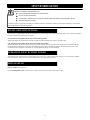
SAFETY INFORMATION
3
Installation and repair should be done only by a qualified service person. The appliance should be inspected by a
qualified service person before use. Annual inspection by a qualified service person is required to maintain warranty.
More frequent cleaning may be required due to excessive lint from carpeting, bedding materials, etc. It is imperative
that control compartments, burners and circulation air passageways of the appliance be kept clean.
This fireplace insert is to be installed into a solid fuel masonry or factory built non-combustible fireplace that has
been installed in accordance with the National, Provincial, State and local building codes.
Children and adults should be alerted to the hazards of high surface temperatures and should stay away to avoid
burns or clothing ignition.
Young children should be carefully supervised when they are in the same room as the appliance. Toddlers, young
children and others susceptible to accidental contact burns. A physical barrier is recommended if there are at risk
individuals in the house. To restrict access to a fireplace or stove, install an adjustable safety gate to keep toddlers,
young children and other at risk individuals out of the room and away from hot surfaces.
Clothing or other flammable material should not be place on or near the appliance.
Adequate accessibility clearances for servicing and proper operation must be maintained.
This appliance must not share or be connected to a chimney flue serving any other appliance.
Keep area around the appliance clear of combustible materials, gasoline and other flammable vapor and liquids.
The flow of combustion and ventilation air must not be obstructed.
Due to high temperatures the appliance should be located out of traffic and away from furniture and draperies.
The glass front or any part removed for servicing the appliance must be replaced prior to operating the appliance.
Work should be done by a qualified service technician.
Clean glass only when cool and only with non-abrasive cleansers.
Do not operate this appliance with the glass/frame assembly removed, cracked or broken. The glass assembly, Part
#TWO-015T, shall only be replaced as a complete unit, as supplied by Hussong Mfg. Co., Inc. Replacement of glass
assembly must only be performed by a licensed or qualified service person. DO NOT SUBSTITUTE MATERIALS.
Do not strike or slam glass assembly.
Any safety screen or guard removed for servicing the appliance must be replaced prior to operating the appliance.
Under no circumstances should any solid fuel (wood, coal, paper or cardboard etc.) be used in this appliance.
Keep burner and control compartment clean.
Do not use this fireplace if any part has been under water. Immediately call a qualified service technician to inspect
this appliance and to replace any part of the control system and any gas control which has been under water.

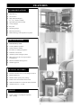
High efficiency
Zero clearance
High quality lifetime glass
21” x 14” (533mm x 356mm)
Quick latch glass frame assembly
Accepts rigid pipe
IPI system
Patented log design
Refractory brick lining
Minnesota Energy Code compliant to 50 pascals
Decorative full door faces in various designs and colors
Red Brick Refractory
Modular cabinet system (patent pending)
Remote control or thermostat remote control
Wall mount thermostat / wireless wall mount thermostat
Automatic fan kit (1) - 75 CFM
Each unit factory tested!
Tested by OMNI Corporation
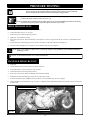
Sealed combustion chamber
Intermittent or standing pilot ignition
Removable control board
Automatic pressure relief glass system
Battery back-up in the event of power failure
(excluding fan)
Bedroom and mobile home approved
Canadian approved
Fireplace Weight (as packaged for shipment)
76lbs. (30.4kg)
4
STANDARD FEATURES
OPTIONAL FEATURES
WEIGHT
SAFETY FEATURES
FEATURES

5
COMMONWEALTH OF MASSACHUSETTS REQUIREMENTS
NOTE: The following requirements reference various Massachusetts and national codes not contained in this manual.
For all sidewall horizontally vented gas fueled equipment installed in every dwelling, building or structure used in whole or in part for residential purposes,
including those owned or operated by the Commonwealth and where the side wall exhaust vent termination is less than (7) feet above finished grade in the
area of the venting, including but not limited to decks and porches, the following requirements shall be satisfied:
INSTALLATION OF CARBON MONOXIDE DETECTORS
At time of installation of side wall horizontally vented gas fueled equipment, the installing plumber or gas-fitter shall observe that a hard wired carbon mon-
oxide detector with an alarm and battery back-up is installed on the floor level where the gas equipment is to be installed. In addition, the installing plumber
or gas-fitter shall observe that a battery operated or hard wired carbon monoxide detector is installed on each additional level of the dwelling, building or
structure served by the side wall horizontal vented gas fueled equipment. It shall be the responsibility of the property owner to secure the services of qualified
licensed professionals for the installation of hard wired carbon monoxide detectors.
In the event that the side wall horizontally vented gas fueled equipment is installed in a crawl space or attic, the hard wired carbon monoxide detector with
alarm and battery back-up may be installed on the next adjacent floor level.
In the event that the requirements of this subdivision can not be met at the time of completion of installation, the owner shall have a period of thirty (30) days
to comply with the above requirements; provided, however, that during said thirty (30) day period, a battery operated carbon monoxide detector with an
alarm shall be installed.
APPROVED CARBON MONOXIDE DETECTORS
Each carbon monoxide detector as required in accordance with the above provisions shall comply with NFPA 720 and be ANSI/UL 2034 listed and IAS
certified.
SIGNAGE
A metal or plastic identification plate shall be permanently mounted to the exterior of the building at a minimum of eight (8) feet above grade directly in line
with the exhaust vent terminal for the horizontally vented gas fueled heating appliance or equipment. The sign shall read, in print no less the one-half inch
(1/2) in size, “GAS VENT DIRECTLY BELOW. KEEP CLEAR OF ALL OBSTRUCTIONS”.
INSPECTION
The state or local gas inspector of the side wall horizontally vented gas fueled equipment shall not approve the installation unless, upon inspection, the
inspector observes carbon monoxide detectors and signage installed in accordance with the provisions of 248 CMR 5.08 (2) (a) 1 through 4.
EXEMPTIONS
The following equipment is exempt from 248 CMR 5.08 (2) (a) 1 through 4:The equipment listed in Chapter 10 entitled “Equipment Not Required To Be
Vented” in the most current edition of NFPA 54 as adopted by the Board; and Product Approved side wall horizontally vented gas fueled equipment installed
in a room or structure separate from the dwelling, building or structure used in whole or in part for residential purposes.
MANUFACTURER REQUIREMENTS - GAS EQUIPMENT VENTING SYSTEM PROVIDED
When the manufacturer of Product Approved side wall horizontally vented gas equipment provides a venting system design or venting system components
with the equipment, the instructions provided by the manufacturer for installation of the equipment and the venting system shall include:
Detailed instructions for the installation of the venting system design or the venting system components; and
A complete parts list for the venting system design or venting system.
MANUFACTURER REQUIREMENTS - GAS EQUIPMENT VENTING SYSTEM NOT PROVIDED
When the manufacturer of Product Approved side wall horizontally vented gas equipment does not provide the parts for venting the flue gases, but identifies
“special venting systems”, the following requirements shall be satisfied by the manufacturer:
The referenced “special venting systems” instructions shall be included with the appliance or equipment installation instructions and;
The “special venting systems” shall be Product Approved by the Board, and the instructions for that system shall include a parts list and detailed
installation instructions.
A copy of all installation instructions for all Product Approved side wall horizontally vented gas fueled equipment, all venting instructions, all parts lists for
venting instructions, and/or all venting design instructions shall remain with the appliance or equipment at the completion of the installation.

From face top - 1” (25mm)
From unit left & right & back sides* - 1/2” (13mm)
Unit side stand-offs to adjacent sidewall - 0” (0mm)
To flooring - 0” (0mm)
From venting -
Horizontal - Top: 3” (76mm)
Bottom and sides: 1” (25mm)
Vertical - All sides: 1” (25mm)
Unit base to ceiling - 52” (1.32m)
Minimum enclosure height - 47” (1.19m)
Top of unit to 3/4” (20mm) projection - 2-1/4” (57mm)
Mantel must be a minimum of 7-1/2” (19mm) from top of fireplace face. The maximum depth at this height is 12” (305mm).
See additional mantel clearance configurations on page 10 of this installation manual.
* This unit requires 1/2” (13mm) space between unit and framing at the back and both sides. Framing material may touch sides of
stand-offs, but no material is allowed between stand-offs.
Side stand-off brackets must be re-positioned if installing in a Kozy Heat Cabinet. Refer to cabinet instructions for details.
SPECIFICATIONS
CLEARANCES
6
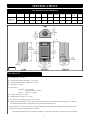
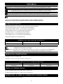
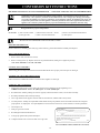
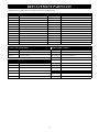
Two Harbors Physical Dimensions
DESCRIPTION Height Width Back Width Depth Top Stand-
off Height
Side Stand-
off Width
Full Door
Face Height
Viewing
Area
Height
Full Door
Face Width
Viewing
Area Width
FIREPLACE
DIMENSIONS
INCHES 31-1/2 18-1/2 5-1/4 14-3/8 1 1/2 33-15/16 17-1/2 21 11-7/8
MILLIMETERS 800 470 133 365 25 13 862 444 533 302
Figure 6a

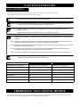
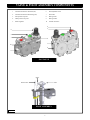
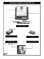
MODEL #55616 COMPONENTS LIST
1. Frame an opening for fireplace, allowing for vent installation and type of installation.
2. If masonry (optional) will be used, prepare foundation for masonry load. A lintel is required to support added weight above fireplace.
3. Insert fireplace into framing.
4. Install hearth (if applicable).
5. Complete gas line installation.
6. Complete electrical hook-up. Install any standard or optional electrical components at this time.
7. Complete venting installation.
8. Secure fireplace to flooring through holes located in outer box bottom and to framing with nailing flanges. Verify all clearances at this
point.
9. Install mantel or cabinetry, allowing room for (required) decorative full doors / faces.
10. Install log set.
11. Install (required) full door face. Follow instructions included with face.
12. Verify proper operation of fireplace and all components.
PLACEMENT CLEARANCE REQUIREMENTS
This fireplace must be installed on a level surface capable of supporting fireplace and venting.
Fireplace must be placed directly on wood or non-combustible surface (not linoleum or carpet) extending entire depth and width of
fireplace.
Due to high surface temperatures, fireplace should be located out of traffic and away from furniture and draperies.
This fireplace may be installed in a bedroom.
Please be aware of the amount of heat this fireplace will produce when determining a location.
SPECIFICATIONS
INSTALLATION OVERVIEW
NOTE: The qualified installer should follow procedure
best suited for the installation.
7
ADDITIONAL COMPONENTS REQUIRED
Vent System: Approved venting listed on page 15 of this installation manual.
Full Door Face: Various finishes available. See Dealer for details.
PART NUMBER DESCRIPTION
TWO-300-IPI
Control Board Assembly
700-203
Manual Gas Shut-off Valve
TWO-135
Burner Assembly
TWO-005
Glass Valance
TWO-15T
Glass with gasket
600-083-3
Double Receptacle /Speed Control Assembly with (3) Wire Nuts
OCK-S57L –I-TWO-SIT
LP Conversion Kit
900-086
5” Restrictor Plate
TWO-HHS
Horizontal Heat Shield

Determine exact position of fireplace, including hearth height, width, and depth, (if applicable). If possible, place fireplace in such a manner
that vent termination will be placed between two studs, eliminating the need for additional framing.
If masonry is to be used (optional), prepare necessary foundation for the masonry load. When masonry construction is being used, a lintel
must be used over top of fireplace to support the added weight.
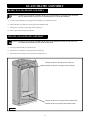
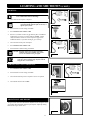
FRAMING
WALL ROUGH OPENING
IMPORTANT: Framing dimensions should allow for wall covering thickness and fireplace facing materials.
If using a hearth, adjust rough opening size as necessary to maintain at least minimum clearance requirements.
IMPORTANT: Non-combustible material man be applied around (but not directly to) fireplace face.
(APPLIES TO BOTH HORIZONTAL AND VERTICAL VENTING TERMINATIONS)
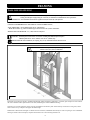
32-5/8” (829mm) High* x 19-3/4”(502mm) Wide x 14-7/8” (378mm) Deep.
* Header must be in the ‘up’ position to maintain proper clearances from vent system to combustibles.
MINIMUM ENCLOSURE HEIGHT: 47” (1.19m) from base of fireplace.
Build hearth to desired size and height. If a hearth extension is desired, combustible material may be used. If carpeting or other combustible
flooring is desired in front of fireplace, fireplace bottom must level or above flooring material level.
WARNING: Install fireplace on hard metal or wood surface extending full width and depth of fireplace.
Minimum platform size: 19-3/4” (502mm) wide x 14-7/8” (378mm) deep.
FIRE HAZARD: Do NOT install directly on carpeting, vinyl, or any combustible material other than wood.
7 8
IMPORTANT: Header must be positioned ‘up’ to maintain proper
clearances from vent system to combustibles.
14-7/8”
(378mm)
19-3/4”
(502mm)
47”
(1.19m)
Figure 8a

Follow vent pipe manufacturer’s installation instructions for horizontal terminations. Include required 3” (76mm) top clearance (at wall
pass-thru) and 1” (25mm) sides and bottom clearances for approved rigid vent systems.
CAUTION: Due to high temperatures, this fireplace should be located out of traffic areas and away from furniture and draperies.
HORIZONTAL TERMINATIONS
Follow vent pipe manufacturer’s installation instructions for vertical terminations. A minimum 1” (25mm) clearance on all sides of vertical
vent pipe must be maintained.
VERTICAL TERMINATIONS
FRAMING
IMPORTANT: Vent cap location must be in compliance with guidelines on page 20 of this manual.
IMPORTANT: KOZY HEAT WALL THIMBLE PASS-THRU (#800-WPT or #800-WPT2) MUST BE USED ON ALL HORIZONTAL VENT RUNS.
FOLLOW INSTRUCTIONS ON PAGE 15 OF THIS INSTALLATION MANUAL.
IMPORTANT: THE HORIZONTAL VENT HEAT SHIELD INCLUDED WITH THIS FIREPLACE MUST BE INSTALLED WHEN USING A 90-
DEGREE ELBOW DIRECTLY OFF TOP OF UNIT TO HORIZONTALLY POSITION VENT SYSTEM.
9
CAUTION: Cold air transfer area. The surrounding fireplace chase must comply with all clearances as outlined in this manual and be
constructed in compliance with local building codes. Outside walls should be insulated to prevent cold air from entering room.
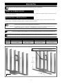
MINIMUM HORIZONTAL FRAMING DIMENSIONS
VENT PIPE TOP (A) FRAMED OPENING TOP (B) TERMINATION WIDTH (W) TERMINATION HEIGHT (H)
RIGID PIPE 41-1/4” (1048mm) 44-1/4” (1124mm) 10-7/8” (276mm) 12-1/2” (318mm)
32-5/8”
(829mm)
19-3/4”
(502mm)
IMPORTANT: Header must be positioned ‘up’ to maintain proper
clearances from vent system to combustibles.
Figure 9a

1” (25mm)
MANTEL REQUIREMENTS
10
IMPORTANT: KOZY HEAT WALL THIMBLE PASS-THRU (#800-WPT or #800-WPT2) MUST BE USED ON ALL HORIZONTAL VENT RUNS.
FOLLOW INSTRUCTIONS ON PAGE 17 OF THIS INSTALLATION MANUAL.
IMPORTANT: THE HORIZONTAL VENT HEAT SHIELD INCLUDED WITH THIS FIREPLACE MUST BE INSTALLED WHEN USING A 90-
DEGREE ELBOW DIRECTLY OFF TOP OF UNIT TO HORIZONTALLY POSITION VENT SYSTEM.
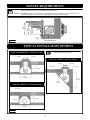
TYPICAL INSTALLATION OPTIONS
TYPICAL HORIZONTAL INSTALLATION
TYPICAL CORNER INSTALLATION
TYPICAL VERTICAL INSTALLATION
NOTE: Horizontal vent heat shield not shown in horizontal
configurations for clarity purposes only.
1” (25mm)
19-3/4”
(502mm)
14-7/8” (378mm)
14-7/8” (378mm)
19-3/4”
(502mm)
1” (25mm)
1/2” (13mm)
1/2” (13mm) 1/2” (13mm)
1” (25mm)
1” (25mm)
1” (25mm)
25-1/4”
(641mm)
35-5/8”
(905mm)
Figure 10a
Figure 10b

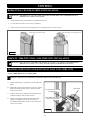
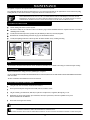
GLASS FRAME ASSEMBLY
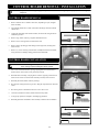
REMOVE GLASS FRAME ASSEMBLY
INSTALL GLASS FRAME ASSEMBLY
11
A. Locate spring-loaded latches securing glass frame assembly at top & bottom of firebox.
CAUTION: TO PREVENT GLASS FRAME ASSEMBLY FROM FALLING FROM FIREPLACE AND BECOMING DAMAGED,
FOLLOW THESE INSTRUCTIONS EXACTLY WHEN REMOVING GLASS FRAME ASSEMBLY.
B. Pull bottom latch out and down to release glass frame assembly bottom.
C. Pull top latch out and up to release glass frame assembly top.
D. Remove glass frame assembly from fireplace.
A. Place glass frame assembly onto fireplace front.
B. Pull top latch out and down to secure glass frame assembly top.
C. Pull bottom latch out and up to secure glass frame assembly bottom.
CAUTION: TO PREVENT GLASS FRAME ASSEMBLY FROM FALLING OFF WHEN INSTALLING, SECURE TOP GLASS
LATCH BRACKETS BEFORE SECURING BOTTOM BRACKETS.
Pull latch out and down to release glass frame assembly bottom.
Pull latch out and up to attach glass frame assembly bottom.
Pull latch out and up to release glass frame assembly top.
Pull latch out and down to attach glass frame assembly top.
Figure 11a

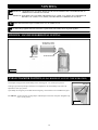
This fireplace is manufactured for use with Natural Gas. An LP conversion kit is included with this fireplace.
Follow instructions included with conversion kit if converting to LP gas.
NATURAL GAS LP GAS
MINIMUM INLET GAS PRESSURE 5.0 inches W.C. (7.0 W.C. recommended) 11.0 inches W.C. (recommended)
MAXIMUM INLET GAS PRESSURE 10.5 inches W.C. 13.0 inches W.C.
MANIFOLD PRESSURE 3.5 inches W.C. 10.0 inches W.C.
MANIFOLD PRESSURE (low setting) 1.6 inches W.C. 6.4 inches W.C.
ORIFICE SIZE #50 #57
INPUT BTU/hr. 14,600 BTU/hr (4.28kW) 14,700 BTU/hr (4.31kW)
MINIMUM INPUT BTU/hr. 10,700 BTU/hr (3.14kW) 10,700 BTU/hr (3.14kW)
GAS LINE CONNECTION
GAS CONVERSION
12
CAUTION: Installation of the gas line must only be done by a qualified person in accordance with local building codes, if any.
If not, follow ANSI 223.1.
Commonwealth of Massachusetts: Installation must be done by a licensed plumber or gas fitter.
IMPORTANT: The efficiency rating of this appliance is a product of thermal efficiency rating determined under continuous operating
conditions and was determined independently of any installed system.
NOTE: A listed (and Commonwealth of Massachusetts approved) 12” (13mm) T-handle manual shut-off valve and flexible gas connector
(included) are connected to the 1/2” (13mm) control valve inlet. If substituting for these components, please consult local codes for
compliance.
NOTE: This fireplace is equipped with a 3/8”(10mm) x 18” (457mm) long flexible gas connector and manual shut-off valve. The gas line
should be run to the point of connection where the shut-off valve and flexible gas line will connect.
NOTE: The appliance and its individual shutoff valve must be disconnected from the gas supply piping system during any pressure testing
of that system at pressures in excess of ½ psi.
NOTE: The appliance must be isolated from the gas supply piping system by closing its individual manual shut-off valve during any
pressure testing of the gas line at test pressures equal to or less than ½ psi (3.5 kPa).
NOTE: For high altitude installations, consult the local gas distributor or the authority having jurisdiction for proper rating methods.
ATTENTION: The conversion shall be carried out in accordance with the requirements of the provincial authorities having jurisdiction and
in accordance with the requirements of the ANSI Z223.1 installation code.
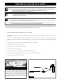
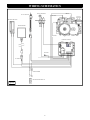
If desired, a thermostat (wireless style also available), wall switch, or remote control assembly may be used to turn fireplace OFF and ON.
Only ONE of these may be installed. Follow instructions included with chosen assembly.
THERMOSTAT / WALL SWITCH / REMOTE
IMPORTANT: We recommend running gas line through left side of fireplace if at all possible. If this cannot be achieved, compensations
must be made for electrical box and transformer location on left side of fireplace.

Refer to vent systems manufacturer's installation manual for complete installation instructions.
Installation must conform with venting requirements and restrictions as outlined in this manual.
Simpson Dura-Vent DV-GS 5” x 8” direct vent system (horizontal and vertical terminations).
Ameri-Vent Direct Chimney System 5” x 8” (horizontal and vertical terminations).
Selkirk Metalbestos Chimney System 5” x 8” (horizontal and vertical terminations).
Metal Fab Chimney System: 5” x 8” (horizontal and vertical terminations).
ICC Chimney System: 5” x 8” (horizontal and vertical terminations).
RLH Chimney System: 5” x 8” (horizontal and vertical terminations).
Security Chimney System: 5” x 8” (horizontal and vertical terminations).
This fireplace is designed to be used with rigid pipe only.
IMPORTANT: Consult local and national installation codes to assure adequate combustion and ventilation air is available.
HORIZONTAL VENT SYSTEM CLEARANCES
TOP BOTTOM SIDES
3 inches (76mm) at wall pass thru 1 inch (25mm) 1 inch (25mm)
HORIZONTAL TERMINATIONS
MINIMUM: 90˚ elbow + termination cap.
MAXIMUM: 90˚ elbow + 8ft. (2.44m) horizontal + termination cap.
VENTING
13
APPROVED VENTING
MINIMUM VERTICAL RISE: 3ft. (914mm) vertical + termination cap.
MAXIMUM VERTICAL RISE: 31ft. (9.45m) vertical + termination cap.
VERTICAL TERMINATIONS
HORIZONTAL & VERTICAL COMBINATION TERMINATIONS
8ft. (2.44m) horizontal / 31ft. (9.45m) vertical.
CAUTION: This gas appliance must not be connected to or joined with any other chimney flue serving another appliance.
VERTICAL VENT SYSTEM CLEARANCES
TOP BOTTOM SIDES
1 inch (25mm) 1 inch (25mm) 1 inch (25mm)
IMPORTANT: Flame height and appearance will vary depending upon venting configuration and type of fuel used.
NOTE: Page 16 has information on restrictor installation in conjunction with venting installation. Page 33 has information on restrictor
recommendations depending on burner flame appearance and instructions on installation after venting is completed.
IMPORTANT: THE HORIZONTAL VENT HEAT SHIELD MUST BE INSTALLED WHEN USING A 90-DEGREE ELBOW TO
HORIZONTALLY POSITION VENT SYSTEM.
IMPORTANT: KOZY HEAT WALL PASS-THRU, PART #800-WPT (4-1/2” (114mm) - 6-1/2” (165mm) ) WALL THICKNESS OR
#800-WPT2 (6-1/2” (165mm) - 12-1/2” (318mm) ), MUST BE USED ON ALL HORIZONTAL VENT RUNS.

IMPORTANT: THE HORIZONTAL VENT HEAT SHIELD MUST BE INSTALLED WHEN USING
A 90-DEGREE ELBOW TO HORIZONTALLY POSITION VENT SYSTEM.
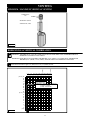
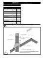
RESTRICTOR INSTALLATION
VENTING
14
A restrictor is included in fireplace components packet.
Each installation is unique and affected by various factors including venting configuration, altitude and climate. Therefore, after fireplace
installation is complete a restrictor may be required or may need to be removed or modified.
Page 33 has information on restrictor recommendations depending on burner flame appearance and instructions on installation after venting
is completed.
RESTRICTOR
Large Restrictor
Bend tabs to approx. 80 degree
angles to create tension to hold
itself in place when installed.
Remove tab (s) to create
small restrictor
Slide restrictor into exhaust pipe on
top of fireplace with tabs pointing
towards you prior to attaching
venting.
For each additional 90° elbow used after first (2) elbows, 3ft. (914mm) must be subtracted from maximum allowed venting. For each 45°
elbow used, 1-1/2ft. (457mm) must be subtracted from maximum venting allowed.
ELBOWS
SECURING VENT SYSTEM
1. Bend (3) tabs on fireplace top up.
2. Install first vent pipe section.
3. Secure vent pipe section to fireplace through tabs with (3) screws.
Figure 16b
Figure 16a
NOTE: (2) 90° elbows may be used within the maximum horizontal and vertical vent
runs. (2) 45° degree elbows may be used in place of (1) 90° elbow.

HORIZONTAL VENT HEAT SHIELD INSTALLATION
VENTING
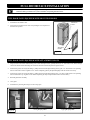
#800-WPT / #800-WPT2 WALL PASS-THRU KITS INSTALLATION
12-1/2” (318mm) HIGH x 10-7/8” (276mm) WIDE
A. Measure wall thickness; cut insulation panel (included) this
length.
B. Install wall pass-thru section marked #1 (with 3/8” (10mm)
flange) into framed opening. Secure to interior wall with
screws (not provided).
C. From the exterior, place insulation between flange and top
of framed opening in wall pass-thru section #1.
D. Install section marked #2 of wall pass-thru into framed
opening, overlapping metal sections as necessary to
accommodate wall thickness. Secure to exterior wall with
screws (not provided).
FRAMING DIMENSIONS FOR KOZY HEAT WALL PASS-THRU KITS
INSULATION
HEAT SHIELD MUST BE FLUSH
WITH WALL PASS -THRU.
WARNING: MAINTAIN ALL CLEARANCES AS STATED IN THIS INSTALLATION MANUAL.
15
3/8” (10mm) FLANGE MUST BE
ON INSIDE WALL.
1. Install 90-degree elbow per manufacturer’s installation instructions.
2. Loosen, but do not remove (2) screws at top of fireplace.
3. Slide (2) slots on horizontal vent heat shield under screws. Re-tighten screws to secure in place.
Loosen, but do not remove screws.
IMPORTANT: THE HORIZONTAL VENT HEAT SHIELD MUST BE INSTALLED WHEN USING A 90-DEGREE ELBOW TO
HORIZONTALLY POSITION VENT SYSTEM.
IMPORTANT: KOZY HEAT WALL PASS-THRU, PART #800-WPT (4-1/2” (114mm) - 6-1/2” (165mm) ) WALL THICKNESS OR
#800-WPT2 (6-1/2” (165mm) - 12-1/2” (318m) ), MUST BE USED ON ALL HORIZONTAL VENT RUNS.
Figure 17b
Figure 17a
Slide slots under screws. Tighten screws.

VENTING
16
MINIMUM / MAXIMUM HORIZONTAL VENTING
EXHAUST DAMPER POSITION (LP GAS HORIZONTAL VENT CONFIGURATION)
This fireplace is shipped with exhaust damper in the closed (approx. 1/2” (13mm) open) position.
If using LP gas and incorporating a horizontal vent configuration, the exhaust damper may need to be
adjusted to a more open position.
Open damper far enough to prevent flame from burning dirty, which results in soot accumulation on glass.
TO ADJUST: Loosen wing nuts securing damper. Slide damper toward front of fireplace. Retighten wing
nuts to secure position.
Wing Nuts
MINIMUM 6in. (152mm)
MAXIMUM 8ft. (2.44m)
TERMINATION
CAP
90-DEGREE ELBOW
NOTE: Horizontal sections require 1/4” (6mm) rise for every 12” (305mm) of travel.
CAUTION: This gas appliance must not be connected to or joined with any other chimney flue serving another appliance.
IMPORTANT: THE HORIZONTAL VENT HEAT SHIELD MUST BE INSTALLED WHEN USING A 90-DEGREE ELBOW TO
HORIZONTALLY POSITION VENT SYSTEM.
IMPORTANT: KOZY HEAT WALL PASS-THRU, PART #800-WPT (4-1/2” (114mm) - 6-1/2” (165mm) ) WALL THICKNESS OR
#800-WPT2 (6-1/2” (165mm) - 12-1/2” (318mm) ), MUST BE USED ON ALL HORIZONTAL VENT RUNS.
Figure 1bb
Figure 18a

HORIZONTAL & VERTICAL COMBINATION
VENTING
17
MINIMUM / MAXIMUM VERTICAL VENTING
NOTE: Horizontal sections require 1/4” (6mm) rise for every 12” (305mm) of travel.
TERMINATION
CAP
MINIMUM 3ft. (914mm)
MAXIMUM 31ft. (9.45m)
IMPORTANT: THE HORIZONTAL VENT HEAT SHIELD MUST BE INSTALLED WHEN USING A 90-DEGREE ELBOW TO
HORIZONTALLY POSITION VENT SYSTEM.
IMPORTANT: KOZY HEAT WALL PASS-THRU, PART #800-WPT (4-1/2” (114mm) - 6-1/2” (165mm) WALL THICKNESS OR
#800-WPT2 (6-1/2” (165mm) - 12-1/2” (318mm) , MUST BE USED ON ALL HORIZONTAL VENT RUNS.
Figure 19b
Figure 19a
0
2
4
6
8
10
12
14
16
20
22
18
24
26
28
30
40
38
36
34
32
10 12 14 16 18 20 22 24 26 28 30
(6.1m)
(6.1m)
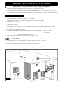
HORIZONTAL / VERTICAL COMBINATION:
(9.45m) 31' Vertical
(2.44m) 8' Horizontal
Termination must be
within shaded area
(ft.)
(12.9m)
(9.14m)
0 2
4
6 8

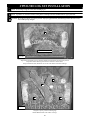
1. Terminations against vinyl siding must use a vinyl siding protector. Follow instructions included.
2. DO NOT RECESS TERMINATION KIT INTO OUTSIDE BUILDING MATERIALS - i.e.: brick, stone, siding, etc. If necessary,
extend framing so that termination kit will be exposed once building materials are installed.
3. Vent termination must not be located where it will become plugged by snow or other material. The flow of combustion and ventilation
air must be not obstructed.
A. Above grade, veranda, porch, deck, balcony - 12" (305mm).
B. Operable window or door - CANADA: 12" (305mm). US: 9” (229mm).
C. Permanently closed window* - 12" (305mm) (recommended to prevent condensation on window).
D. Ventilated soffit* - 18" (457mm).
E. Unventilated soffit* - 11" (279mm).
F. Outside corner* - 0" (0mm).
G. Inside corner* - 1” (25mm).
H. Meter / Regulator: Not to be installed above a gas meter/regulator assembly within 3ft. (914mm) horizontally from the centerline
of the regulator.
I. Gas Service regulator vent outlet - 3ft. (914mm).
J. Non-mechanical air supply inlet to building or the combustion air inlet to any other appliance. CANADA: 12" (305mm).
US: 9” (229mm).
K. Mechanical air supply inlet. CANADA: 6ft. (1.83m) US: 3ft. (914mm) above if within 10ft. (3.05m) horizontally.
Massachusetts installations: 10ft. (3.05m).
L. Above paved side-walk or paved driveway located on public property - 7ft. (2.13m).
This gas appliance must not be connected to a chimney serving any other appliance.
TERMINATION VENT CAP LOCATION
LOCATION CLEARANCES
NOTE: A vent cannot be located directly above a side-walk or paved driveway that is located between two single family dwellings and
serves both dwellings.
M. Under veranda, porch, deck, or balcony (must be fully opened on a minimum of 2 sides) - 12" (305mm).
N. Between two horizontal terminations - 12" (305mm).
O. Between two vertical terminations - 12" (305mm). Terminations may be same height.
P. Above furnace exhaust or inlet - 12" (305mm).
*Clearance must be in accordance with local installation codes & the requirements of the gas supplier.
18
Figure 20a
Denotes where installation not allowed

19
Roof Pitch H (Min.) Ft. H (Min.) m
Flat to 6/12 1.0 0.30
Over 6/12 to 7/12 1.25 0.38
Over 7/12 to 8/12 1.5 0.46
Over 8/12 to 9/12 2.0 0.61
Over 9/12 to 10/12 2.5 0.76
Over 10/12 to 11/12 3.25 0.99
Over 11/12 to 12/12 4.0 1.22
Over 12/12 to 14/12 5.0 1.52
Over 14/12 to 16/12 6.0 1.83
Over 16/12 to 18/12 7.0 2.13
Over 18/12 to 20/12 7.5 2.27
Over 20/12 to 21/12 8.0 2.44
VENT TERMINATION CLEARANCES
VENTING (Vertical Cap Requirements)
CAUTION: This appliance must not be connected to or joined with any chimney flue serving any other appliance.
*(2.44m)
* IF VENT IS CLOSER THAN 8ft. (2.44m), IT MUST TERMINATE AT
LEAST 2ft. (0.61m) HIGHER THAN ANY PORTION OF A BUILDING
WITHIN 10ft. (3.05m) OF THE VENT.
Figure 21a
20
Page is loading ...
Page is loading ...
Page is loading ...
Page is loading ...
Page is loading ...
Page is loading ...
Page is loading ...
Page is loading ...
Page is loading ...
Page is loading ...
Page is loading ...
Page is loading ...
Page is loading ...
Page is loading ...
Page is loading ...
Page is loading ...
Page is loading ...
Page is loading ...
Page is loading ...
Page is loading ...
Page is loading ...
Page is loading ...
Page is loading ...
Page is loading ...
Page is loading ...
-
 1
1
-
 2
2
-
 3
3
-
 4
4
-
 5
5
-
 6
6
-
 7
7
-
 8
8
-
 9
9
-
 10
10
-
 11
11
-
 12
12
-
 13
13
-
 14
14
-
 15
15
-
 16
16
-
 17
17
-
 18
18
-
 19
19
-
 20
20
-
 21
21
-
 22
22
-
 23
23
-
 24
24
-
 25
25
-
 26
26
-
 27
27
-
 28
28
-
 29
29
-
 30
30
-
 31
31
-
 32
32
-
 33
33
-
 34
34
-
 35
35
-
 36
36
-
 37
37
-
 38
38
-
 39
39
-
 40
40
-
 41
41
-
 42
42
-
 43
43
-
 44
44
-
 45
45


Kozyheat Two Harbors Owner's manual
- Category
- Fireplaces
- Type
- Owner's manual
Ask a question and I''ll find the answer in the document
Finding information in a document is now easier with AI
Related papers
-
Kozyheat Two Harbors Owner's manual
-
-
-
kozy heat Nicollet Owner's manual
-
kozy heat #961 Owner's manual
-
-
-
-
-
Other documents
-
Rheem XG40T06PN36U1 Installation guide
-
Breckwell BH3024 User manual
-
Fireplace Xtrordinair 4237 Ember-Glo Fireplace 2021 Framing Guide
-
Heat & Glo WH-STAT Wall Thermostat Kit Installation and Operation Instructions
-
Enviro Indoor Fireplace ENVIRO User manual
-
-
LG LFXS29626S LG Measure First Installation Guide
-
LG LFXS24623S LG Measure First Refrigerator Guide
-
Minolta RAVL42 User manual
-
LG RAVENNA RDV3340 User manual