Page is loading ...

Tracer CH530™
Control System for Chillers
RTWD/RTUD 060-250
User Guide
RLC-SVU05A-E4

General information
RLC-SVU05A-E4
Foreword
These instructions are given as a
guide to good practice in the
installation, start-up, operation, and
maintenance by the user, of Trane
CH530 chiller control system on
chillers. They do not contain full
service procedures necessary for
the continued successful operation
of this equipment. The services of a
qualified technician should be
employed through the medium of a
maintenance contract with a
reputable service company. Read
this manual thoroughly before unit
start-up.
Warnings and cautions
Warnings and Cautions appear at
appropriate sections throughout
this manual. Your personal safety
and the proper operation of this
machine require that you follow
them carefully. The constructor
assumes no liability for installations
or servicing performed by
unqualified personnel.
WARNING! : Indicates a potentially
hazardous situation which, if not
avoided, could result in death or
serious injury.
CAUTION! : Indicates a potentially
hazardous situation which, if not
avoided, may result in minor or
moderate injury. It may also be
used to alert against unsafe
practices or for equipment or
property-damage-only accidents.
Safety recommendations
To avoid death, injury, equipment
or property damage, the following
recommendations should be
observed during maintenance and
service visits:
1. Disconnect the main power
supply before any servicing on
the unit.
2. Service work should be carried
out only by qualified and
experienced personnel.
Reception
On arrival, inspect the unit before
signing the delivery note.
Reception in France only:
In case of visible damage: The
consignee (or the site
representative) must specify any
damage on the delivery note,
legibly sign and date the delivery
note, and the truck driver must
countersign it. The consignee (or
the site representative) must notify
Trane Epinal Operations - Claims
team and send a copy of the
delivery note. The customer (or the
site representative) should send a
registered letter to the last carrier
within 3 days of delivery.
Reception in all countries except
France:
In case of concealed damage: The
consignee (or the site
representative) must send a
registered letter to the last carrier
within 7 days of delivery, claiming
for the described damage. A copy
of this letter must be sent to Trane
Epinal Operations - Claims team.
Note: for deliveries in France, even
concealed damage must be looked
for at delivery
and immediately
treated as visible damage.
© 2009 Trane

General information
3RLC-SVU05A-E4
Warranty
Warranty is based on the general
terms and conditions of the
manufacturer. The warranty is void
if the equipment is repaired or
modified without the written
approval of the manufacturer, if the
operating limits are exceeded or if
the control system or the electrical
wiring is modified. Damage due to
misuse, lack of maintenance or
failure to comply with the
manufacturer's instructions or
recommendations is not covered by
the warranty obligation. If the user
does not conform to the rules of
this manual, it may entail
cancellation of warranty and
liabilities by the manufacturer.
Maintenance contract
It is strongly recommended that you
sign a maintenance contract with
your local Service Agency. This
contract provides regular
maintenance of your installation by
a specialist in our equipment.
Regular maintenance ensures that
any malfunction is detected and
corrected in good time and
minimizes the possibility that
serious damage will occur. Finally,
regular maintenance ensures the
maximum operating life of your
equipment. We would remind you
that failure to respect these
installation and maintenance
instructions may result in
immediate cancellation of the
warranty.
Training
To assist you in obtaining the best
use of it and maintaining it in
perfect operating condition over a
long period of time, the
manufacturer has at your disposal a
refrigeration and air conditioning
service school. The principal aim of
this is to give operators and
technicians a better knowledge of
the equipment they are using, or
that is under their charge. Emphasis
is particularly given to the
importance of periodic checks on
the unit operating parameters as
well as on preventive maintenance,
which reduces the cost of owning
the unit by avoiding serious and
costly breakdown.


Overview
5RLC-SVU05A-E4
The Trane CH530 control system
that runs the chiller consists of
several elements:
• The main processor collects
data, status, and diagnostic
information and communicates
commands to the
LLID (for Low
Level Intelligent Device)
bus. The
main processor has an integral
display (DynaView).
•
LLID bus
. The main processor
communicates to each input and
output device (e.g. temperature
and pressure sensors, low
voltage binary inputs, analog
input/output) all connected to a
four-wire bus, rather than the
conventional control architecture
of signal wires for each device.
• The
communication interface
to
a building automation system
(BAS).
•A
service tool
to provide all
service/maintenance capabilities.
Main processor and service tool
(TechView) software is
downloadable from
www.Trane.com
. The process is
discussed later in this section
under TechView Interface.
DynaView provides bus
management. It has the task of
restarting the link, or filling in for
what it sees as "missing" devices
when normal communications
has been degraded. Use of
TechView may be required.
The CH530 uses the IPC3 protocol
based on RS485 signal technology
and communicating at 19.2 Kbaud
to allow 3 rounds of data per
second on a 64-device network.
Most diagnostics are handled by the
DynaView. If a temperature or
pressure is reported out of range by
a LLID, the DynaView processes this
information and calls out the
diagnostic. The individual LLIDs are
not responsible for any diagnostic
functions.
Note: It is imperative that the CH530
Service Tool (TechView) be used to
facilitate the replacement of any
LLID or reconfigure any chiller
component.
Controls Interface
DynaView (picture on cover)
Each chiller is equipped with the
DynaView interface. DynaView has
the capability to display additional
information to the advanced
operator including the ability to
adjust settings. Multiple screens are
available and text is presented in
multiple languages as factory-
ordered or can be easily
downloaded online.
TechView
TechView can be connected to the
DynaView module and provides
further data, adjustment
capabilities, diagnostics
information, downloadable
software, and downloadable
languages.

DynaView Interface
RLC-SVU05A-E46
Power Up
On power-up, Dynaview will
progress through 3 screens.
The first screen (Figure 1) will
display for 3-10 seconds. This
screen will give the status of the
Application software, the Boot
Software P/N, selftest results and
the application part number. The
contrast is adjustable from this
screen. The message "Selftest
passed" may be replaced with "Err2:
RAM Error" or "Err3: CRC Failure"
Figure 1
Figure 2
Note that the Application and Boot
software numbers will vary
according to the unit type.
If no application is found, the screen
(Figure 2) will display instead of
Figure 1.

DynaView Interface
7RLC-SVU05A-E4
The second screen (Figure 3) will
display for 15-25 seconds. If a valid
configuration is present, "Tracer
CH530" will also be displayed. If the
MP configuration is found to be
invalid, "MP: Invalid Configuration"
is displayed indefinitely. Contact
your local Trane service technician.
Figure 3
Figure 4
The third screen is the first screen
of the application.

DynaView Interface
RLC-SVU05A-E48
The display on DynaView is a
1/4 VGA display with a resistive
touch screen and an LED backlight.
The display area is approximately
4 inches wide by 3 inches high
(102mm x 60mm).
CAUTION!
Equipment Damage! Putting
excessive pressure on the touch
screen could cause damage. It takes
less than 7 kg of force to break the
screen.
In this touch screen application, key
functions are determined
completely by software and change
depending upon the subject matter
currently being displayed. The basic
touch screen functions are outlined
below.
Radio Buttons
Radio buttons show 1 menu choice
among 2 or more alternatives, all
visible. The possible selections are
each associated with a button. The
selected button is darkened,
presented in reverse video to
indicate it is the selected choice.
The full range of possible choices
as well as the current choice is
always in view.
Spin Value Buttons
Spin values are used to allow a
variable setpoint to be changed,
such as leaving water setpoint. The
value increases or decreases by
touching the (+) or (-) arrows.
Action Buttons
Action buttons appear temporarily
and provide the user with a choice
such as Enter or Cancel.
File Folder Tabs
File folder tabs are used to select a
screen of data. The tabs are in
1 row across the top of the display.
The user selects a screen of
information by touching the
appropriate tab.
Display Screens
The main body of the screen is used
for description text, data, setpoints,
or keys (touch sensitive areas). The
Chiller Mode is displayed here.
A double arrow pointing to the right
indicates more information is
available about the specific item on
that same line. Pressing it will bring
you to a sub-screen that will
present the information or allow
changes to settings.
Figure 5 - Basic Screen Format
9

DynaView Interface
9RLC-SVU05A-E4
The bottom of the screen (7) is
present in all screens and contains
the following functions. The
contrast (8,9) may require re-
adjustment at ambient
temperatures significantly different
from those present at last
adjustment. The other functions are
critical to machine operation. The
AUTO and STOP keys are used to
enable or disable the chiller. The
key selected is in black (reverse
video). The chiller will stop when
the STOP key is touched and after
completing the Run Unload mode.
Touching the AUTO key will enable
the chiller if no diagnostic is
present. (A separate action must be
taken to clear active diagnostics.)
The AUTO and STOP keys take
precedence over the Enter and
Cancel keys. (While a setting is
being changed, AUTO and STOP
keys are recognized even if Enter or
Cancel has not been pressed.) The
ALARMS button appears only when
an alarm is present, and blinks (by
alternating between normal and
reverse video) to draw attention to
a diagnostic condition. Pressing the
ALARMS button takes you to the
corresponding tab for additional
information.
Note: screens may differ according
to unit type or configuration. They
should be considered as examples.
Keypad/Display Lockout
Feature
Note: The DynaView display and
Touch Screen Lock screen is shown
above. This screen is used if the
Display and touch screen and lock
feature is enabled. Thirty minutes
after the last keystroke, this screen
is displayed and the Display and
Touch Screen is locked out until the
sequence "159 <ENTER>" is
pressed. Until the proper password
is entered, there will be no access
to the DynaView screens including
all reports, setpoints, and
Auto/Stop/Alarms/Interlocks. The
password "159" can not be changed
from either DynaView or TechView.
For setting changes, use the
password "314 <ENTER>".
System/Circuit Selection Buttons
On some report and setting screens,
radio buttons on the top of the
screen shall be presented to allow
the user to select subscreens based
on system-level data and per-circuit
data.
For single-circuit units with
system/circuit selection buttons, the
buttons shall be labeled (in English)
“System” and “Ckt”. For two-circuit
units with system/circuit selection
buttons, the buttons shall be
labeled “System”, “Ckt1”, and
“Ckt2”.
Figure 6 - Keypad
1

DynaView Interface
RLC-SVU05A-E410
Main Screens
The Main screen is a “dashboard”
of the chiller. High level status
information is presented so that a
user can quickly understand the
mode of operation of the chiller.
The Chiller Operating Mode will
present a top level indication of the
chiller mode (i.e. Auto, Running,
Inhibit, Run Inhibit, etc.) The
“additional info” icon will present a
subscreen that lists in further detail
the subsystem modes.
Figure 7 - Main screen
Main
Main
Reports
Reports
Settings
Settings
Auto
Auto
Stop
Stop
Chiller Mode:
Circuit 1 Mode:
Circuit 2 Mode:
Evap Ent / Lvg Water Temp:
Cond Ent / Lvg Water Temp:
Active Chilled Water Setpoint:
Running
Running - Limit
Auto
12 / 7 C
30 / 35 C
7 C
The Main screen shall be the default
screen. After an idle time of
30 minutes the CH530 shall display
the Main screen with the first data
fields. The remaining items (listed
in the following table) will be
viewed by selecting the up/down
arrow icons.

DynaView Interface
11RLC-SVU05A-E4
Table 1 - Main Screen Data Fields Table
Description Units Resolution Dependencies
1. Chiller Mode (>> submodes) enumeration
2. Circuit 1 Mode (>> submodes) enumeration
3. Circuit 2 Mode (>> submodes) enumeration
4. Evap Ent/Lvg Water Temp F / C 0.1
5. Cond Ent/Lvg Water Temp F / C 0.1
6.
F / C 0.1
7.
F / C 0.1 Hot Water Option installed only
8. Average Line Current %RLA 1
9.
% RLA 1
10. Active Ice Termination Setpoint
11. (>>front panel setpoint) F / C 0.1 If Ice Building Option is installed
12. Outdoor Air Temperature F / C 0.1 Only if OA sensor is installed
13. Software Type enumeration RTWD / RTUD
14. Software Version X.XX
Figure 8 - Active Chilled Water Subscreen
:
Active Water Setpoint Arbitration
Subscreen
The active water setpoint is that
setpoint to which the unit is
currently controlling. It is the result
of arbitration between the front
panel, BAS, and external setpoints.
The active chilled water water
setpoint may also be subjected to a
form of chilled water reset.
Touching the double arrow to the
left of the Active Chilled Water
Setpoint or to the left of the Active
Hot Water Setpoint will take the
user to the respective active water
setpoint arbitration sub-screen.
Chiller Mode
The machine-operating mode
indicates the operational status of
the chiller. A subscreen with
additional mode summary
information will be provided by
selection of an additional
information icon (>>). The
operating mode line will remain
stationary while the remaining
status items scroll with the up/down
arrow keys.
Active Chilled Water Setpoint and
Active Hot Water Setpoint
The active chilled water setpoint is
the setpoint that is used in cool
mode. The active hot water setpoint
is the setpoint that is used in heat
mode. Both setpoints result from
the logical hierarchy of setpoint
arbitration by the main processor.
The water setpoint will be displayed
to 0.1 degrees Fahrenheit or
Celsius.
Active Chilled Water Setpoint (>>source) (>> front panel setpoint) -
from arbitration setpoint screen
Active Current Limit Setpoint (>> source) (>> front panel
setpoint) - from arbitration setpoint screen
Active Hot Water Setpoint (>>source) (>> front panel
setpoint) - from arbitration setpoint screen
Water Cooled only (i.e. RTWD or
RTUD with ACFC=None)

DynaView Interface
RLC-SVU05A-E412
Other Active Setpoints
The Active Current Limit Setpoint
will behave the same way as the
Active Chilled Water Setpoint, with
the exception that Active Current
Limit Setpoint does not have an
external source.

DynaView Interface
13RLC-SVU05A-E4
Chiller Operating Mode
The machine-operating mode indicates the operational status of the chiller.
A subscreen with additional mode summary information will be provided
by selection of an additional information icon (>>). The operating mode line
will remain stationary while the remaining status items scroll with the
up/down arrow keys.
Table 2 - Main screen menu, Chiller Operating Modes - Top Level
Chiller Level Mode
Top Level Mode Description
Stopped
The chiller is not running either circuit, and cannot run without intervention.
Stopped Sub Modes Description
Local Stop Chiller is stopped by the DynaView Stop button command- cannot be remotely overridden.
Immediate Stop
Chiller is stopped by the DynaView Immediate Stop (by pressing the Stop then Immediate Stop
buttons in succession) - previous shutdown was manually commanded to shutdown immediately.
No Circuits Available The entire chiller is stopped by circuit diagnostics or lockouts that may automatically clear.
Diagnostic Shutdown - Manual Reset The chiller is stopped by a diagnostic that requires manual intervention to reset.
Cond Pmp Strt Dly (Head Pres Ctrl) min:sec
Only possible when Condenser Head Pressure Control option is enabled and the condenser pump is
being manually commanded to run - this wait may be necessary due to the Head Pressure control
device's stroke time.
Chiller Level Mode
Top Level Mode Description
Run Inhibit
The chiller is currently being inhibited from starting (and running), but may be allowed to start if the
inhibiting or diagnostic condition is cleared.
Run Inhibit Sub Modes Description
No Circuits Available The entire chiller is stopped by circuit diagnostics or lockouts that may automatically clear.
Ice Building Is Complete
The chiller is inhibited from running as the Ice Building process has been normally terminated on the
evaporator entering temperature. The chiller will not start unless the ice building command (hardwired
input or Building Automation System command) is removed or cycled.
Ice to Normal Transition
The chiller is inhibited from running for a brief period of time if it is commanded from active ice
building mode into normal cooling mode via the ice building hardwired input or Tracer. This allows time
for the external system load to "switchover" from an ice bank to the chilled water loop, and provides for
a controlled pull down of the loop's warmer temperature. This mode is not seen if the ice making is
automatically terminated on return brine temperature per the mode below.
Start(ing is)* Inhibited by BAS (Building
Automation System)*
Chiller is stopped by Tracer or other BAS system.
Start(ing is)* Inhibited by External Source The chiller is inhibited from starting or running by the "external stop" hardwired input.
Diagnostic Shutdown - Auto Reset The entire chiller is stopped by a diagnostic that may automatically clear.
Waiting for BAS Communications (to Establish
Operating Status)*
The chiller is inhibited because of lack of communication with the BAS. This is only valid 15 minutes
after power up.
Start(ing is)* Inhibited by Low Ambient
Temp(erature)*
The chiller is inhibited based on the outdoor air temperature.
Start(ing is)* Inhibited by Local Schedule The chiller is inhibited from starting based on the local time of day scheduling (option)

DynaView Interface
RLC-SVU05A-E414
Chiller Level Mode
Top Level Mode Description
Auto
The chiller is not currently running but can be expected to start at any moment given that the proper
conditions and interlocks are satisfied.
Auto Sub Modes Description
Waiting For Evap(orator)* Water Flow
The unit will wait up to 20 minutes in this mode for water flow to be established per the flow switch
hardwired input.
Waiting For A Need To Cool
The chiller will wait indefinitely in this mode, for a leaving water temperature higher than the Chilled
Water Setpoint plus some control dead-band.
Waiting For A Need To Heat
The chiller will wait indefinitely in this mode, for a leaving water temperature lower than the Hot Water
Setpoint plus some control dead-band.
Power Up Delay Inhibit: min:sec On Power up, the chiller will wait for the Power Up Delay Timer to expire.
Chiller Level Mode
Top Level Mode Description
Waiting to Start
The chiller is not currently running and there is a call for cooling but the lead circuit start is delayed by
certain interlocks or proofs. Further information is provided by the sub-mode:
Waiting to Start
Sub Modes
Description
Waiting For Condenser Water Flow
The chiller will wait up to 4 minutes in this mode for condenser water flow to be established per the
flow switch hardwired input.
Cond Water Pump PreRun Time min:sec
The chiller will wait up to 30 minutes (user adjustable) in this mode for to allow the condenser water
loop to equalize in temperature
Cond Pmp Strt Dly (Head Pres Ctrl) min:sec
Only possible when Condenser Head Pressure Control option is enabled, this wait may be necessary
due to the Head Pressure control device's stroke time.
Cprsr Strt Delay (Head Pres Ctrl) min:sec
Only possible when Condenser Head Pressure Control option is enabled, this wait may be necessary
due to the Head Pressure control device's stroke time
Chiller Level Mode
Top Level Mode Description
Running
At least one circuit on the chiller is currently running.
Running Sub Modes Description
Maximum Capacity The chiller is operating at its maximum capacity.
Capacity Control Softloading The control is limiting the chiller loading due to capacity based softloading setpoints.
Current Control Softloading
The chiller is running, and loading of individual compressors may be limited by a gradual filter of the
chiller's softloading current limit setpoint. The starting current limit and the settling time of this filter is
user adjustable as part of the current control softload feature. The mode will be displayed as long as
the Current Control Softloading limit is ramping or "settling".
Chiller Level Mode
Top Level Mode Description
Running - Limit
At least one circuit on the chiller is currently running, but the operation of any of the circuits on the
chiller is being actively limited by a chiller level limit. Other sub modes that apply to the Chiller
Running top level modes may also be displayed here. Refer to the list of circuit limit modes for circuit
limits that will cause display of this Chiller Level Running Limit mode.
Running - Limit
Sub Modes
Description
<none applicable>
Design Note: Hot Start Limit is applied and annunciated at a circuit level, even though it is based on
the chiller's leaving water temperature.

DynaView Interface
15RLC-SVU05A-E4
Chiller Level Mode
Top Level Mode Description
Shutting Down
The chiller is still running but shutdown is imminent. The chiller is going through a compressor run-
unload or extended operational pumpdown of the lag circuit/compressor (or all circuits
simultaneously).
Shutting Down Sub Modes Description
Operational Pumpdown
The lag circuit (or all circuits) is in the process shutting down by performing an operational pumpdown
just prior to stopping the circuit's compressor. The EXV is commanded closed. Pumpdown will
terminate when both the liquid level and the evap pressure are low (below specific criteria) or after a
specific time has expired.
Evaporator Water Pump Off Delay: MIN:SEC
The Evaporator water pump is continuing to run past the shutdown of the compressors, executing the
pump off delay timer.
Cond Water Pump Off Delay: MIN:SEC
The Condenser water pump is continuing to run past the shutdown of the compressors, executing the
pump off delay timer.
Chiller Level Mode
Top Level Mode Description
Misc.
These sub modes may be displayed in most of the top level chiller modes
Misc. Sub Modes Description
Manual Evap(orator)* Water Pump Override The Evaporator water pump relay is on due to a manual command.
Diagnostic Evap Water Pump Override The Evaporator water pump relay is on due to a diagnostic.
Diagnostic Cond Water Pump Override The Condenser water pump relay is on due to a diagnostic.
Local Schedule Active
The local time of day scheduler (option) is operational and could automatically change modes or
setpoints as scheduled
Manual Condenser Water Pump Override The condenser water pump relay is on due to a manual command.
Manual Compressor Control Signal Chiller capacity control is being controlled by DynaView or TechView.
Night Noise Setback
The Night Noise Setback feature has been activated. If the unit is running, fans will be running at low
speed.
Hot Water Control
These modes are mutually exclusive and they indicate that the chiller is controlling to the active hot
water setpoint, the active chilled water setpoint, or the active ice termination setpoint respectively.
Chilled Water Control
Ice Building

DynaView Interface
RLC-SVU05A-E416
Table 2 - Circuit Level Operating Modes
Circuit Level Mode
Top Level Mode Description
Stopped
The circuit is not running, and cannot run without intervention.
Stopped Sub Modes Description
Diagnostic Shutdown - Manual Reset The circuit has been shutdown on a latching diagnostic.
Front Panel Circuit Lockout
The circuit is manually locked out by the circuit lockout setting - the nonvolatile lockout setting is
accessible through either the DynaView or TechView.
External Circuit Lockout The respective circuit is locked out by the external circuit lockout binary input.
Circuit Level Mode
Top Level Mode Description
Run Inhibit
The given circuit is currently being inhibited from starting (and running), but may be allowed to start if
the inhibiting or diagnostic condition is cleared.
Run Inhibit
Sub Modes
Description
Diagnostic Shutdown - Auto Reset The circuit has been shutdown on a diagnostic that may clear automatically.
Low Oil Flow Cool Down Time mn:sc The cool-down period is necessary to allow the compressor rotors to cool after starts.
Restart Inhibit min:sec
The compressor (and therefore, its circuit) is currently unable to start due to its restart inhibit timer. A
given compressor is not allowed to start until 5 minutes (adj) has expired since its last start, once a
number of "free starts" have been used up.
Circuit Level Mode
Top Level Mode Description
Auto
The circuit is not currently running but can be expected to start at any moment given that the proper
conditions are satisfied.
Auto Sub Modes Description
Calibrating EXV
This submode is displayed when the EXV is performing a calibration. A calibration is only performed
when the chiller is not running and never more frequently than once every 24 hours
Circuit Level Mode
Top Level Mode Description
Waiting to Start
The chiller is going through the necessary steps to allow the lead circuit to start.
Waiting to Start
Sub Modes
Description
Start Inhibited Waiting For Oil
The compressor (and thus its circuit) will wait up to 2 minutes in this mode for oil level to appear in the
oil tank.
Waiting For EXV Preposition
The Chiller will wait for the time it takes the EXV to get to its commanded pre-position prior to starting
the compressor. This is typically a relatively short delay and no countdown timer is necessary (less
than 15 seconds)

DynaView Interface
17RLC-SVU05A-E4
Circuit Level Mode
Top Level Mode Description
Running
The compressor on the given circuit is currently running.
Running
Sub Modes
Description
Establishing Min(imum)* Cap(acity)* - Low
Diff(errential)* Pressure
The circuit is experiencing low system differential pressure and its compressor is being force loaded,
irregardless Chilled Water Temperature Control, to develop pressure sooner.
Establishing Min Cap - High Disch Temp
The circuit is running with high discharge temperatures and its compressor is being forced loaded to
its step load point, without regard to the leaving water temperature control, to prevent tripping on high
compressor discharge temperature.
The following modes annunciations have not been implemented as a display but are actually operational in the EXV liquid level control algorithm. The
modes included here as possible future annunciated modes
EXV Controlling Differential Pressure
Liquid level control of the Electronic Expansion Valve has temporarily been suspended. The EXV is
being modulated to control for a minimum differential pressure. This control implies low liquid levels
and higher approach temperatures, but only as is necessary to provide minimum oil flow for the
compressor until the condenser water loop can warm up to approx 50F. (Future mode display - display
of mode not implemented in Phase 1 or 2 although present in algorithms.)
EXV Controlling for Low Evaporator Pressure
Liquid level control of the Electronic Expansion Valve has temporarily been suspended. The EXV is
being modulated to control for a minimum evaporator pressure that is based of the pressure of the
Low Refrigerant Temperature Cutout. This control will tend to increase the liquid level above the
setpoint or to open the valve more quickly than liquid level control can, in order to avoid an LRTC trip.
It is most often invoked transiently to help open the EXV in the event of rapidly falling liquid level and
rapidly declining evaporator pressures. (Future Mode display, - display of mode not implemented in
Phase 1 or 2 although present in algorithms.)
Circuit Level Mode
Top Level Mode Description
Running - Limit
The circuit, and compressor are currently running, but the operation of the chiller/compressor is being
actively limited by the controls. Further information is provided by the sub-mode.* See the section
below regarding criteria for annunciation of limit modes
Running - Limit
Sub Modes
Description
Current Limit
The compressor is running and its capacity is being limited by high currents. The current limit setting
is 120% RLA (to avoid overcurrent trips) or lower as set by the compressor's "share" of the active
current limit (demand limit) setting for the entire chiller.*
High Condenser Pressure Limit
The circuit is experiencing condenser pressures at or near the condenser limit setting. Compressors
on the circuit will be unloaded to prevent exceeding the limits.*
Low Evaporator Rfgt Temperature Limit
The circuit is experiencing saturated evaporator temperatures at or near the Low Refrigerant
Temperature Cutout setting. Compressors on the circuit will be unloaded to prevent tripping. *
Hot Start Limit
This mode will occur if the leaving evaporator water temperature exceeds 75F (for SW version 6.30
and earlier) or 90 F (for software 7.01 and later) at the point at which the step load for the respective
circuit would be desired. This is often the case in a high water temperature pulldown. While in this
mode, no compressor on the circuit will be allowed to load past its minimum load capacity step, but it
will not inhibit other compressors from staging on. This mode is necessary to prevent nuisance trips
due to Compressor Overcurrent or High Pressure Cutout. Reasonable pulldown rates can still be
expected despite this limit, since the compressor's capacity even at partial load is much greater at
high suction temperatures.

DynaView Interface
RLC-SVU05A-E418
* Mode text strings in parenthesis for TechView display only - available space for DynaView text strings is limited.
Circuit Level Mode
Top Level Mode Description
Shutting Down
The circuit is preparing to de-energize the compressor.
Preparing Shutdown
Sub Modes
Description
Operational Pumpdown
The circuit is in the process shutting down by performing an operational pumpdown just prior to
stopping the last running compressor. The EXV is commanded closed. Pumpdown will terminate
when both the liquid level and the evap pressure are low (below specific criteria) or after a specific
time has expired.
Compressor Unloading: MIN:SEC
The compressor is in its run unload time. The number of seconds remaining in run unload is shown in
the submode. The run unload time must expire before the compressor will shut down.
Circuit Level Mode
Top Level Mode Description
Misc.
These sub modes may be displayed in most of the top level circuit modes
Misc. Sub Modes Description
Service Pumpdown The circuit is currently performing a service pumpdown.
Restart Time Inhibit: MIN:SEC If there is accumulated Restart Inhibit Time, it must expire before a compressor is allowed to start.

DynaView Interface
19RLC-SVU05A-E4
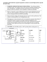
Reports Screen
The Reports tab will allow a user to
select from a list of possible reports
headings (i.e. Custom, ASHRAE
Guideline 3, Refrigerant, etc.).
Each report will generate a list of
status items as defined in the
following tables.
Figure 9 - Reports screen
Table 3- Reports Screen
Report Menu
Description
1. Evaporator
2. Condenser
3. Compressor
4. ASHRAE Chiller Log
5. Historic Diagnostics
Report name: System Evaporator
<| Back System Ckt1 Ckt2
<scroll up/down buttons>
Description Resolution Units Dependencies
1. Evap Entering Water Temperature + XXX.X Temperature
2. Evap Leaving Water Temperature + XXX.X Temperature
3. Evap Water Flow Switch Status (Flow, No Flow) Enum
Report name: Circuit Evaporator
<| Back System Ckt1 Ckt2
<scroll up/down buttons>
Description Resolution Units Dependencies
1. Evap Entering Water Temperature + XXX.X Temperature
2. Evap Leaving Water Temperature + XXX.X Temperature
3. Evap Sat Rfgt Temp + XXX.X Temperature
4. Suction Pressure XXX.X Pressure
5. Evap Approach Temp + XXX.X Temperature
6. Evap Water Flow Switch Status (Flow, No Flow) Enum
7. Expansion Valve Position XXX.X Percent
8. Expansion Valve Position Steps XXXX Steps
9. Evaporator Liquid Level XX.X Height
Main Reports Settings
Auto Stop Alarms
Evaporator
Condenser
Compressor
ASHRAE Chiller Log
Historic Diagnostics

DynaView Interface
RLC-SVU05A-E420
Report name: System Condenser
<| Back System Ckt1 Ckt2
<scroll up/down buttons>
Description Resolution Units Dependencies
1. Cond Entering Water Temp + XXX.X Temperature Water Cooled only (i.e. RTWD or RTUD with ACFC=None)
2. Cond Leaving Water Temp + XXX.X Temperature Water Cooled only (i.e. RTWD or RTUD with ACFC=None)
3. Cond Water Flow Switch Status (Flow, No Flow) Enum Water Cooled only (i.e. RTWD or RTUD with ACFC=None))
4. Outdoor Air Temperature + XXX.X Temperature Only if OA sensor is installed
5. Cond Head Pressure Ctrl Command XXX % Only if Cond Head pressure control option is installed
Report name: Circuit Condenser
<| Back System Ckt1 Ckt2
<scroll up/down buttons>
Description Resolution Units Dependencies
1. Cond Entering Water Temp + XXX.X Temperature Water Cooled only (i.e. RTWD or RTUD with ACFC=None)
2. Cond Leaving Water Temp + XXX.X Temperature Water Cooled only (i.e. RTWD or RTUD with ACFC=None)
3. Condenser Air Flow XXX % Air Cooled (i.e RTUD with ACFC=INT)
4. Cond Inverter Speed XXX %
5. Outdoor Air Temperature + XXX.X Temperature Only if OA sensor is installed
6. Cond Water Flow Switch Status (Flow, No Flow) Enum Water Cooled only (i.e. RTWD or RTUD with ACFC=None)
7. Cond Sat Rfgt Temp + XXX.X Temperature
8. Cond Rfgt Pressure XXX.X Pressure
9. Differential Pressure XXX.X Pressure
10. Cond Approach Temp + XXX.X Temperature Water Cooled only (i.e. RTWD or RTUD with ACFC=None)
Report name: System Compressor
<| Back System Ckt1 Ckt2
<scroll up/down buttons>
Description Resolution Units Dependencies
1. Average Line Current XXX %RLA
2. Unit Volts XXX Volts
3. Unit Running Time XXXX:XX hr:min
4. Power Demand kW Only if pwr meter option installed
5. Power Demand Time Period min Only if pwr meter option installed
6. Energy Consump-Resettable kWh Only if pwr meter option installed
7. Time of Last Reset time-date Only if pwr meter option installed
8. Energy Consump-NonReset Kwh Only if pwr meter option installed
Air Cooled with Low Ambient Var Spd fan (i.e RTUD with ACFC<>None and
with LAFC = VARA or VARP)
/