Page is loading ...

DMPS3-4K-150-C
3-Series
®
4K DigitalMedia™ Presentation
System 150
Supplemental Guide
Crestron Electronics, Inc.

The product warranty can be found at www.crestron.com/warranty.
The specific patents that cover Crestron products are listed at patents.crestron.com.
Certain Crestron products contain open source software. For specific information, please visit www.crestron.com/opensource.
Crestron, the Crestron logo, .AV Framework, 3-Series, 3-Series Control System, Cresnet, Crestron Connect It, Crestron Toolbox,
DigitalMedia, DM, and DM 8G+ are either trademarks or registered trademarks of Crestron Electronics, Inc. in the United States and/or
other countries. HDBaseT is either a trademark or registered trademark of the HDBaseT Alliance in the United States and/or other countries.
HDMI is either a trademark or registered trademark of HDMI Licensing LLC in the United States and/or other countries. Other trademarks,
registered trademarks, and trade names may be used in this document to refer to either the entities claiming the marks and names or their
products. Crestron disclaims any proprietary interest in the marks and names of others. Crestron is not responsible for errors in typography
or photography.
This document was written by the Technical Publications department at Crestron.
©2016 Crestron Electronics, Inc.

Supplemental Guide – DOC. 7724A Contents • i
Contents
Introduction 1
Physical Description 2
Front Panel.............................................................................................................. 2
Rear Panel .............................................................................................................. 3
.AV Framework Technology 5
Crestron Connect It Functionality 5
Integrated 3-Series Control System 5
Configuration 6
Adjustable Underscan ............................................................................................. 6
Configuration Using the Web Interface ....................................................... 6
Configuration Using SIMPL Windows ......................................................... 7
User-Selectable Output Resolution ......................................................................... 7
Configuration Using the Web Interface ....................................................... 7
Configuration Using SIMPL Windows ......................................................... 7
Standby Timeout ..................................................................................................... 8
Configuration Using the Web Interface ....................................................... 8
Configuration Using SIMPL Windows ......................................................... 8
Display Mode .......................................................................................................... 9
Configuration Using the Web Interface ....................................................... 9
Configuration Using SIMPL Windows ......................................................... 9
EDID ..................................................................................................................... 10
Connection to Third-Party HDBaseT Equipment ................................................... 10
Adding a Third-Party HDBaseT Transmitter ............................................. 11
Adding a Third-Party HDBaseT Receiver .................................................. 11
Troubleshooting 13
Appendix: Pin Assignments 14


Supplemental Guide – DOC. 7724A DMPS3-4K-150-C: 3-Series 4K DigitalMedia Presentation System • 1
DMPS3-4K-150-C:
3-Series
®
4K DigitalMedia™
Presentation System 150
Introduction
The Crestron
®
DMPS3-4K-150-C is an ultra high-definition presentation switcher that
integrates a control system, multiformat switcher, 4K video scaler, mic preamp, and
audio DSP. The DMPS3-4K-150-C provides out-of-the-box Crestron Connect It™
collaboration and also includes built-in .AV Framework™ technology.
This guide provides information about the following:
• Physical description of the front and rear panels of the DMPS3-4K-150-C
• .AV Framework technology, Crestron Connect It functionality, and 3-Series Control
System
®
integration supported by the DMPS3-4K-150-C
• Configuration of some of the capabilities of the DMPS3-4K-150-C, for example,
adjustable underscan
• Troubleshooting
• Pin assignments
For installation information, refer to the DMPS3-4K-150-C DO Guide (Doc. 7654) at
www.crestron.com/manuals
.

2 • DMPS3-4K-150-C: 3-Series 4K DigitalMedia Presentation System Supplemental Guide – DOC. 7724A
Physical Description
This section provides information about the connectors, controls, and indicators on the front
and rear panels of the DMPS3-4K-150-C.
Front Panel
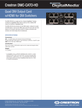
The following illustration shows the front panel of the DMPS3-4K-150-C.
DMPS3-4K-150-C Front Panel
COMPUTER: USB Type B female;
USB computer console port;
For setup only
PWR: Bicolor green/amber LED, indicates operating power supplied from ac line
power, turns amber while booting and green when operating
NET: Yellow LED, indicates Cresnet
®
bus activity
MSG: Red LED, indicates internal control system has generated an error message
HW-R: Recessed push button for hardware reset, reboots the control system
SW-R: Recessed push button for software reset, restarts the software program
IR IN: Infrared sensor;
IR Frequency: 36 to 38 kHz;
IR Formats: Crestron format, RC5;
Allows control from IR wireless remotes using the Crestron or RC-5 command sets
AUTO INPUT SELECT: Push button and bicolor green/amber LED, selects automatic
switching mode
VGA INPUT SELECT 1-4: Push buttons for manual input selection and corresponding
bicolor green/amber LEDs that indicate the current active input and signal presence at
each corresponding VGA input
HDMI INPUT SELECT 1-4: Push buttons for manual input selection and
corresponding bicolor green/amber LEDs that indicate the current active input and
signal presence at each corresponding HDMI
®
input
DM INPUT SELECT 1-2: Push buttons for manual input selection and corresponding
bicolor green/amber LEDs that indicate the current active input and signal presence at
each corresponding DM
®
input
VOLUME: Continuous turn rotary encoder, adjusts the analog audio output volume

Supplemental Guide – DOC. 7724A DMPS3-4K-150-C: 3-Series 4K DigitalMedia Presentation System • 3
Rear Panel
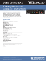
The following illustration shows the rear panel of the DMPS3-4K-150-C.
DMPS3-4K-150-C Rear Panel
VGA IN 1-4: HD15 female;
Analog VGA/RGB/video inputs;
Signal Types: VGA, RGB, component, S-video, or composite;
Formats: RGBHV, RGBS, RGsB, YPbPr, Y/C, NTSC or PAL;
Input Level: 0.5 to 1.5 Vp-p with built-in DC restoration;
Input Impedance: 75 Ohms nominal;
Sync Detection: RGBHV, RGBS, RGsB, YPbPr;
Sync Input Level: 3 to 5 Vp-p;
Sync Input Impedance: 2.2k Ohms
NOTE: The VGA inputs can accept component, composite, and S-video signals using
an appropriate adapter (not included). However, input sync detection is not provided for
composite or S-video signal types.
AUDIO IN 1-4: 3.5 mm TRS mini phone jacks;
Unbalanced stereo line-level analog audio inputs;
Input Impedance: 32k Ohms unbalanced;
Maximum Input Level: 2.8 Vrms unbalanced
NOTE: If an HDMI input is selected but no digital audio signal is detected, the
corresponding analog audio input is activated (AUDIO 1 for HDMI 1, AUDIO 2 for
HDMI 2, and so on). The analog audio inputs do not pass audio if the HDMI video input
resolution is higher than 1920 x 1200.
HDMI 1-4: 19-pin Type A HDMI female;
Digital video/audio inputs;
Signal Types: HDMI, DVI, or Dual-Mode DisplayPort
NOTE: The HDMI inputs require an appropriate adapter or interface cable to
accommodate a DVI signal or Dual-Mode DisplayPort signal. The CBL-HD-DVI interface
cable is sold separately.
2
3
4

4 • DMPS3-4K-150-C: 3-Series 4K DigitalMedia Presentation System Supplemental Guide – DOC. 7724A
DM IN 1-2: 8-pin RJ-45 female, shielded;
DM 8G+
®
inputs, HDBaseT
®
standard compliant;
PoDM PSE (Power Sourcing Equipment) ports
(HDBaseT PoE compatible);
Each connects to the DM 8G+ output of a DigitalMedia transmitter or other DM device
or to an HDBaseT device via CAT5e, Crestron DM-CBL-8G, or Crestron
DM-CBL-ULTRA cable;
Green LED indicates DM link status;
Solid amber LED indicates HDCP video;
Blinking amber LED indicates non-HDCP video
NOTE: Any wiring that is connected to a PoDM or HDBaseT PoE PSE port is for
intrabuilding use only and should not be connected to a line that runs outside of the
building in which the PSE is located.
HDMI OUT: 19-pin Type A HDMI female;
Digital video/audio output;
Signal Types: HDMI, DVI
NOTE: The HDMI output requires an appropriate adapter or interface cable to
accommodate a DVI signal or Dual-Mode DisplayPort signal. The CBL-HD-DVI interface
cable is sold separately.
DM OUT: 8-pin RJ-45 female, shielded;
DM 8G+ output, HDBaseT standard compliant;
PoDM PSE (Power Sourcing Equipment) port
(HDBaseT PoE compatible);
Connects to the DM 8G+ input of a DigitalMedia receiver or other DM device or to an
HDBaseT device via CAT5e, Crestron DM-CBL-8G, or Crestron DM-CBL-ULTRA cable;
Green LED indicates DM link status;
Solid amber LED indicates HDCP video;
Blinking amber LED indicates non-HDCP video
RELAY 1-2: 4-pin 3.5 mm detachable terminal block;
Comprises 2 normally open, isolated relays;
Rated 1 Amp, 30 volts ac/dc;
MOV arc suppression across contacts
INPUT 1-2: 3-pin 3.5 mm detachable terminal block;
Comprises 2 programmable digital inputs;
Input Voltage Range: 0 to 24 Vdc, referenced to GND;
Logic Threshold: 2.5 Vdc nominal with 1 Volt hysteresis band;
Input Impedance: 10k Ohms at >5 volts, 1M Ohms at <5 volts;
Pull-up Resistor: 2.2k Ohms per input
MIC IN: 3-pin 3.5 mm detachable terminal block;
Balanced microphone audio input;
Input Level: -60 to 0 dBV, 1 Vrms maximum;
Input Impedance: 6.5k Ohms balanced;
Phantom Power: 48 Vdc, software enabled/disabled
LAN: 8-pin RJ45 female;
10BASE-T/100BASE-TX Ethernet port
Ground ( ): 6-32 screw, chassis ground lug
100-240 V~1.4 A 50/60 Hz: IEC 60320 C14 mains power inlet;
Mates with removable power cord, included

Supplemental Guide – DOC. 7724A DMPS3-4K-150-C: 3-Series 4K DigitalMedia Presentation System • 5
AUDIO OUT: 5-pin 3.5 mm detachable terminal block;
Balanced/unbalanced stereo line-level audio output;
Output Impedance: 200 Ohms balanced, 100 Ohms unbalanced;
Maximum Output Level: 4 Vrms balanced, 2 Vrms unbalanced
IR OUT: 3.5 mm mini-phone jack;
IR/serial output port;
IR output up to 1.2 MHz;
1-way serial TTL/RS-232 (0-5 volts) up to 115.2k baud
COM: 5-pin 3.5 mm detachable terminal block;
Bidirectional RS-232 port;
Up to 115.2k baud, hardware and software handshaking support
USB 1-4: USB Type A female;
USB 2.0 host ports for TT-100 series Crestron Connect It cable caddies
(sold separately);
Also enable firmware update via USB flash drive
NET: 4-pin 3.5 mm detachable terminal block;
Cresnet master port;
Available Cresnet Power: 24 watts
For pin assignment information, refer to the Appendix on page 14.
.AV Framework Technology
Built-in .AV Framework technology allows a fully functional DMPS3-4K-150-C presentation
system without the need for additional programming. The .AV Framework setup and
management tool allows simplified configuration of the DMPS3-4K-150-C.
For additional information, refer to the .AV Framework™ Software for DMPS3 Operations
Guide (Doc. 7887) at www.crestron.com\manuals
.
Crestron Connect It Functionality
The DMPS3-4K-150-C provides built-in Crestron Connect It functionality, allowing USB
connections of up to four TT-100 series Crestron Connect It cable caddies (sold separately).
The auto-switching inputs of the DMPS3-4K-150-C support individual HDMI, VGA, and
analog audio connections at each cable caddy.
Integrated 3-Series Control System
The DMPS3-4K-150-C includes an integrated 3-Series Control System that allows
programmable room control. The built-in control system enables the DMPS3-4K-150-C to
provide customizable control of every AV device as well as room lighting, window shades,
and projection screens. The control ports of the DMPS3-4K-150-C include one IR port, one
RS-232 COM port, two relay ports, and two digital input ports. In addition, Cresnet and
Ethernet ports are also provided.

6 • DMPS3-4K-150-C: 3-Series 4K DigitalMedia Presentation System Supplemental Guide – DOC. 7724A
Configuration
In addition to the .AV Framework setup and management tool, the DMPS3-4K-150-C can
be configured using the web interface, which can be accessed from a web browser by
entering the IP address or hostname of the DMPS3-4K-150-C. SIMPL Windows can also be
used to configure the DMPS3-4K-150-C.
This section provides information about configuration of the following items using the web
interface or SIMPL Windows:
• Adjustable underscan
• User-selectable output resolution
• Standby timeout
• Display mode
• EDID
• Connection to third-party HDBaseT equipment
Adjustable Underscan
If content does not fit properly on a display, adjustments to underscan may be desired.
Adjustments can be made up to 7.5%. Adjusting the underscan reduces the image size by
the specified percentage so that the entire video frame is displayed.
To adjust underscan, use the DMPS3-4K-150-C web interface or SIMPL Windows as
discussed in the following sections.
Configuration Using the Web Interface
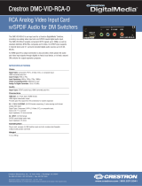
An overview of the steps necessary to adjust the underscan setting is as follows:
NOTE: For detailed information, refer to the online help of the web interface.
1. On the Main Setup page, click the INTERNAL SCALER Settings button.
The Output Configuration page for the internal scaler opens.
2. In the Image Size list, click the radio button that corresponds to the desired
underscan setting.
Output Configuration Page for Internal Scaler—Image Size (Underscan) Configuration

Supplemental Guide – DOC. 7724A DMPS3-4K-150-C: 3-Series 4K DigitalMedia Presentation System • 7
Configuration Using SIMPL Windows
Using SIMPL Windows, adjust underscan in subslot 02 of the Outputs slot for the
DMPS3-4K-150-C. Set the
<Scaler_Underscan_Mode> analog input join to the desired
value.
NOTE: For detailed information, refer to the SIMPL Windows help file.
User-Selectable Output Resolution
The output resolution of the scaler is user selectable. To select the output resolution, use
the web interface or SIMPL Windows as discussed in the following sections.
Configuration Using the Web Interface
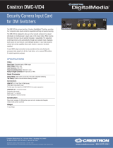
An overview of the steps necessary to select the output resolution of the scaler is as follows:
NOTE: For detailed information, refer to the online help of the web interface.
1. On the Main Setup page, click the INTERNAL SCALER Settings button.
The Output Configuration page for the internal scaler opens.
2. In the Current Scaler Resolution list, click the desired setting.
3. (Applicable only when EDID Preferred is selected in the Current Scaler Resolution
list) In the
Preferred EDID list, click the radio button that corresponds to the
preferred EDID setting.
Output Configuration Page for Internal Scaler—Current Scaler Resolution Configuration
Configuration Using SIMPL Windows
Using SIMPL Windows, set the output resolution in subslot 02 of the Outputs slot for the
DMPS3-4K-150-C. To do so, set the
<Scaler_User_Resolution_Index> analog input join
to the desired value.
NOTE: For detailed information, refer to the SIMPL Windows help file.

8 • DMPS3-4K-150-C: 3-Series 4K DigitalMedia Presentation System Supplemental Guide – DOC. 7724A
Standby Timeout
Standby timeout sets the period of time after which the output will shut down if no video is
detected on the input.
To configure Standby Timeout settings, use the web interface or SIMPL Windows as
discussed in the following sections.
Configuration Using the Web Interface
An overview of the steps necessary to configure the Standby Timeout setting is as follows:
NOTE: For detailed information, refer to the online help of the web interface.
1. On the Main Setup page, click the INTERNAL SCALER Settings button.
The Output Configuration page for the internal scaler opens.
2. Adjust the Timeout slider to the desired value.
Output Configuration Page for Internal Scaler—Timeout Configuration
Configuration Using SIMPL Windows
Using SIMPL Windows, set the standby timeout in subslot 02 of the Outputs slot for the
DMPS3-4K-150-C. To do so, set the
<Scaler_Out_Standby_Timeout> analog input join to
the desired value.
NOTE: For detailed information, refer to the SIMPL Windows help file.

Supplemental Guide – DOC. 7724A DMPS3-4K-150-C: 3-Series 4K DigitalMedia Presentation System • 9
Display Mode
The display mode of an image can be set to one of the following:
• Maintain aspect ratio
• Stretch to fit
• 1:1 pixel mapping
• Zoom
To configure Display Mode settings, use the web interface or SIMPL Windows as discussed
in the following sections.
Configuration Using the Web Interface
An overview of the steps necessary to configure the display mode is as follows:
NOTE: For detailed information, refer to the online help of the web interface.
1. On the Main Setup page, click the INTERNAL SCALER Settings button.
The Output Configuration page for the internal scaler opens.
2. In the Display Mode list, click the radio button that corresponds to the desired
setting.
Output Configuration Page for Internal Scaler—Display Mode Configuration
Configuration Using SIMPL Windows
Using SIMPL Windows, set the display mode in subslot 02 of the Outputs slot for the
DMPS3-4K-150-C. To do so, set the
<Scaler_Display_Mode> analog input join to the
desired value.
NOTE: For detailed information, refer to the SIMPL Windows help file.

10 • DMPS3-4K-150-C: 3-Series 4K DigitalMedia Presentation System Supplemental Guide – DOC. 7724A
EDID
EDID (Extended Display Identification Data) configuration allows management of the EDID
that is to be sent to the upstream device connected to a VGA, HDMI, or DM 8G+ input of
the DMPS3-4K-150-C. If an EDID other than the default EDID is desired, use the web
interface to configure the EDID. An overview of the steps necessary to configure the EDID is
as follows:
NOTE: For detailed information, refer to the online help of the web interface.
1. On the Main Setup page, click the input whose EDID is to be configured.
The Input Configuration page for the selected input opens.
2. Click the Configure EDID button. The EDID Setup page opens.
3. Configure the EDID as desired.
EDID Setup Page
Connection to Third-Party HDBaseT Equipment
The DMPS3-4K-150-C is HDBaseT certified, enabling direct connection to other HDBaseT
certified equipment. Via DM 8G+ technology, the DMPS3-4K-150-C can be connected to a
third-party HDBaseT transmitter or receiver device without requiring a DM 8G+ transmitter
or receiver.
To add a third-party HDBaseT transmitter or receiver to the DMPS3-4K-150-C, use SIMPL
Windows. An overview of the necessary steps for adding an HDBaseT transmitter or
receiver follows.
NOTE: For detailed information, refer to the SIMPL Windows help file.

Supplemental Guide – DOC. 7724A DMPS3-4K-150-C: 3-Series 4K DigitalMedia Presentation System • 11
Adding a Third-Party HDBaseT Transmitter
In the Configure View of SIMPL Windows, add a third-party HDBaseT transmitter to the
DMPS3-4K-150-C by doing the following:
1. Follow the menu path:
Slot:8:DMPS3 Control >> Slot:2:AV Control >> Slot:2:Inputs >>
Slot:9:DM Input 1 or Slot:10:DM Input 2
2. Add the HDBaseT transmitter to an empty transmitter slot.
Addition of HDBaseT Transmitter
Adding a Third-Party HDBaseT Receiver
In the Configure View of SIMPL Windows, add a third-party HDBaseT receiver to the
DMPS3-4K-150-C by doing the following:
1. Follow the menu path:
Slot:8:DMPS3 Control >> Slot:2:AV Control >> Slot:3:Outputs >>
Slot:2:DM/HDMI Output
2. Add the HDBaseT receiver to an empty receiver slot.

12 • DMPS3-4K-150-C: 3-Series 4K DigitalMedia Presentation System Supplemental Guide – DOC. 7724A
Addition of HDBaseT Receiver

Supplemental Guide – DOC. 7724A DMPS3-4K-150-C: 3-Series 4K DigitalMedia Presentation System • 13
Troubleshooting
The following table provides troubleshooting information. If further assistance is required,
contact a Crestron customer service representative.
DMPS3-4K-150-C Troubleshooting
TROUBLE POSSIBLE CAUSE(S) CORRECTIVE ACTION
The video is not being
displayed but the audio may
be heard.
The HDCP settings of one or more
DigitalMedia devices in the signal
path do not support the HDCP level
of the source.
Ensure that the HDCP
settings of all DigitalMedia
devices in the signal path
support the HDCP level of the
source.
The display does not support the
HDCP level of the source.
Ensure that the display
supports the HDCP level of
the source.
The video is intermittent.
The HDMI cable connections are
faulty.
Verify that each end of the
cable is connected properly.
A message indicating that the
resolution is unsupported
appears on the display.
The scaler is not set to a resolution
that the display can support.
Change the scaler resolution
setting to a resolution that the
display can support.
The DMPS3-4K-150-C
cannot establish a link to the
device that is connected to
the DM IN or DM OUT port.
The DM link status LED is off.
The cable connections are faulty.
Verify that each end of the
cable is properly connected. If
necessary, check the cable
terminations.
Analog audio is not being
heard from the device
connected to the AUDIO OUT
port of the DMPS3-4K-150-C.
The EDID is not set to 2-channel
audio in the web interface.
Set the EDID to 2-channel
audio.
The analog audio output is not
programmed properly in SIMPL
Windows.
Ensure that the analog audio
output is programmed
properly.
The volume is not set properly in
web interface or in SIMPL
Windows.
Verify that the volume is set
properly.
The mixer is not enabled on the
selected input in the web interface.
Ensure that the mixer is
enabled on the selected input.
The video flickers or drops
when the DMPS3-4K-150-C
is touched or when metal in
the vicinity of the device is
touched.
The DMPS3-4K-150-C is not
properly grounded.
Ensure that the
DMPS3-4K-150-C is properly
grounded.
NOTE: If, for any reason, the factory default settings of the DMPS3-4K-150-C must be
restored, do the following: From the Tools menu in the Crestron Toolbox application, select
Text Console and enter the following command:
restore

14 • DMPS3-4K-150-C: 3-Series 4K DigitalMedia Presentation System Supplemental Guide – DOC. 7724A
Appendix: Pin Assignments
This section provides information about pin assignments and wiring for the following
DMPS3-4K-150-C connectors:
• VGA IN
• DM IN and DM OUT
• AUDIO OUT
• LAN
VGA IN Pin Assignments
PIN
NUMBER
RGB
YPbPr
S-Video
Composite
1 R Pr C
2 G Y Y
3 B Pb COMP
5 GND GND GND GND
6 RED_GND Pr_GND C_GND
7 GRN_GND Y_GND Y_GND
8 BLU_GND Pb_GND
13 H
14 V
NOTE:
For best video performance, ground connections should be
kept separate. Do not connect ground wires to the connector shell.
The connector shell is reserved for the cable shield.
DM IN and DM OUT Pin Assignments and Wiring
PIN
NUMBER
WIRE
COLOR
PIN
NUMBER
WIRE
COLOR
1 Orange/White 5 Blue/White
2 Orange 6 Green
3 Green/White 7 Brown/White
4 Blue 8 Brown
Pin 10
Pin 5
Pin 1
Pin 6
Pin 15 Pin 11
5
1
11
15
Pin 1Pin 8

Supplemental Guide – DOC. 7724A DMPS3-4K-150-C: 3-Series 4K DigitalMedia Presentation System • 15
AUDIO OUT Pin Assignments and Wiring
SIGNAL
NAME
BALANCED
AUDIO OUTPUT
UNBALANCED
AUDIO OUTPUT
+ L+ L+ Out
– L– Open
G Shield/Ground Common Ground
+ R+ R+ Out
– R– Open
LAN Pin Assignments
PIN
NUMBER
SIGNAL
PIN
NUMBER
SIGNAL
1 TX+ 5 N/C
2 TX– 6 RX–
3 RX+ 7 N/C
4 N/C 8 N/C
+
+
–
–
AM
P
Left
R
ight
+
-
G
+
-
Unbalanced Output
L R
+
+
Shield
AMP
Left
Right
+
-
G
+
-
Balanced Output
L R
+
+
Pin 1
Pin 8

Crestron Electronics, Inc. Supplemental Guide – DOC. 7724A
15 Volvo Drive Rockleigh, NJ 07647 (2047535)
Tel: 888.CRESTRON 11.16
Fax: 201.767.7576 Specifications subject to
www.crestron.com change without notice.
/