Miller AUTO ARC 255 Owner's manual
- Category
- Welding System
- Type
- Owner's manual
This manual is also suitable for
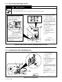
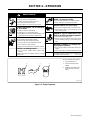
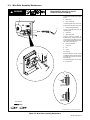
Miller AUTO ARC 255 is a DC/CV welding power source and wire feeder designed for GMAW and FCAW welding. It can weld with hard wires from .023 to .045 inches in diameter and flux-cored wires from .030 to .045 inches in diameter. The AUTO ARC 255 has a maximum output of 200 amps at 28 volts DC and a 60% duty cycle. It also features overheating and motor overload protection, a built-in gun and shielding gas valve, and a variety of welding modes and settings to suit different welding applications.
Miller AUTO ARC 255 is a DC/CV welding power source and wire feeder designed for GMAW and FCAW welding. It can weld with hard wires from .023 to .045 inches in diameter and flux-cored wires from .030 to .045 inches in diameter. The AUTO ARC 255 has a maximum output of 200 amps at 28 volts DC and a 60% duty cycle. It also features overheating and motor overload protection, a built-in gun and shielding gas valve, and a variety of welding modes and settings to suit different welding applications.


-
 1
1
-
 2
2
-
 3
3
-
 4
4
-
 5
5
-
 6
6
-
 7
7
-
 8
8
-
 9
9
-
 10
10
-
 11
11
-
 12
12
-
 13
13
-
 14
14
-
 15
15
-
 16
16
-
 17
17
-
 18
18
-
 19
19
-
 20
20
-
 21
21
-
 22
22
-
 23
23
-
 24
24
-
 25
25
-
 26
26
-
 27
27
-
 28
28


Miller AUTO ARC 255 Owner's manual
- Category
- Welding System
- Type
- Owner's manual
- This manual is also suitable for
Miller AUTO ARC 255 is a DC/CV welding power source and wire feeder designed for GMAW and FCAW welding. It can weld with hard wires from .023 to .045 inches in diameter and flux-cored wires from .030 to .045 inches in diameter. The AUTO ARC 255 has a maximum output of 200 amps at 28 volts DC and a 60% duty cycle. It also features overheating and motor overload protection, a built-in gun and shielding gas valve, and a variety of welding modes and settings to suit different welding applications.
Ask a question and I''ll find the answer in the document
Finding information in a document is now easier with AI
Related papers
-
Miller AUTO ARC 255 Owner's manual
-
-
-
-
-
Miller MW100 Owner's manual
-
-
-
-
Other documents
-
HobartWelders HANDLER 120/150 Owner's manual
-
-
Hobart Welding Products 150 User manual
-
-
-
Dynascan DS72LT6 User manual
-
Keystone KoolSpot Silver Series Installation guide
-
EXELAIR 209 User manual
-
Teeter FreeStep LT3 Operating instructions
-