Page is loading ...
Page is loading ...

3
PERSONAL SAFETY
GENERAL POWER TOOL SAFETY WARNINGS
WORK AREA SAFETY
ELECTRICAL SAFETY
•Keepworkareacleanandwelllit. Cluttered or
dark areas invite accidents.
•Donotoperatepowertoolsinexplosiveatmos-
pheres,suchasinthepresenceofammable
liquids,gasesordust. Power tools create sparks
which may ignite the dust or fumes.
•Keep children andbystanders away while
operatingapowertool. Distractions can cause
you to lose control.
•Powertoolplugsmustmatchtheoutlet.Never
modifythepluginanyway.Donotuseany
adapterplugswithearthed(grounded)power
tools.Unmodied plugs and matching outlets will
reduce risk of electric shock.
•Avoidbodycontactwithearthedorgrounded
surfacessuchaspipes,radiators,rangesand
refrigerators.There is an increased risk of electric
shock if your body is earthed or grounded.
•Donotexposepowertoolstorainorwetcondi-
tions.Water entering a power tool will increase
the risk of electric shock.
•Donotabusethecord.Neverusethecordfor
carrying,pullingorunpluggingthepowertool.
Keepcord awayfromheat, oil,sharpedges
ormovingparts.Damaged or entangled cords
increase the risk of electric shock.
•Whenoperatingapowertooloutdoors,usean
extensioncordsuitableforoutdooruse.Use
of a cord suitable for outdoor use reduces the risk
of electric shock.
•Ifoperatingapowertoolinadamplocation
isunavoidable,usearesidualcurrentdevice
(RCD)protectedsupply.Use of an RCD reduces
the risk of electric shock.
•Removeanyadjustingkeyorwrenchbefore
turningthepowertoolon.A wrench or a key left
attached to a rotating part of the power tool may
result in personal injury.
•Donot overreach. Keep proper footing and
balanceatalltimes. This enables better control
of the power tool in unexpected situations.
•Dressproperly.Donotwearlooseclothingor
jewellery.Keepyourhair,clothingandgloves
awayfrommovingparts. Loose clothes, jewel-
lery or long hair can be caught in moving parts.
•If devices are provided for the connectionof
dustextractionandcollectionfacilities,ensure
theseareconnectedandproperlyused.Use of
dust collection can reduce dust-related hazards.
WARNING READ ALL SAFETY WARNINGS AND ALL INSTRUCTIONS. Failure
tofollowthewarningsandinstructionsmayresultinelectricshock,reand/orserious
injury.Save all warnings and instructions for future reference. Theterm"power
tool"inthewarningsreferstoyourmains-operated(corded)powertoolorbattery-operated
(cordless)powertool.
POWER TOOL USE AND CARE
•Donotforcethepowertool.Usethecorrect
powertoolforyourapplication. The correct
power tool will do the job better and safer at the
rate for which it was designed.
•Donotusethepowertooliftheswitchdoesnot
turnitonandoff. Any power tool that cannot be
controlled with the switch is dangerous and must
be repaired.
•Disconnecttheplugfromthepowersource
and/orthebattery pack fromthepowertool
beforemakinganyadjustments,changing
accessories,orstoringpowertools.Such pre-
ventive safety measures reduce the risk of starting
the power tool accidentally.
•Storeidlepowertoolsoutofthereachofchil-
drenanddonotallowpersonsunfamiliarwith
thepowertoolortheseinstructionstooperate
thepowertool.Power tools are dangerous in the
hands of untrained users.
•Maintainpowertools.Checkformisalignment
orbindingofmovingparts,breakageofparts
andanyotherconditionthat may affect the
powertool’soperation.Ifdamaged,havethe
powertoolrepairedbeforeuse.Many accidents
are caused by poorly maintained power tools.
•Keepcuttingtoolssharpandclean. Properly
maintained cutting tools with sharp cutting edges
are less likely to bind and are easier to control.
•Usethepowertool,accessoriesandtoolbits
etc.,inaccordancewiththeseinstructions,
takingintoaccounttheworkingconditionsand
theworktobeperformed.Use of the power tool
for operations different from those intended could
result in a hazardous situation.
•Stayalert,watchwhatyouaredoinganduse
commonsensewhenoperatingapowertool.Do
notuseapowertoolwhileyouaretiredorunder
theinuenceofdrugs,alcoholormedication.A
moment of inattention while operating power tools
may result in serious personal injury.
•Usepersonal protective equipment.Always
weareyeprotection. Protective equipment such
as dust mask, non-skid safety shoes, hard hat, or
hearing protection used for appropriate conditions
will reduce personal injuries.
•Prevent unintentional starting. Ensure the
switchisintheoff-positionbeforeconnecting
topowersourceand/orbatterypack,picking
uporcarryingthetool.Carrying power tools with
your nger on the switch or energising power tools
that have the switch on invites accidents.
SERVICE
•Haveyourpowertoolservicedbyaqualied
repairpersonusingonlyidenticalreplacement
parts.This will ensure that the safety of the power
tool is maintained.

4
SPECIFIC SAFETY RULES
Safety Warnings Common for Grinding,
Sanding,WireBrushing,orAbrasiveCutting-
OffOperations:
•This power tool is intended to function as
a grinder, sander, wire brushing or cut-off
tool. Read all safety warnings, instructions,
illustrationsandspecificationsprovidedwith
thispowertool.Failure to follow all instructions
listed below may result in electric shock, fire and/
or serious injury.
•Operations such as polishing are not
recommendedtobeperformedwiththispower
tool. Operations for which the power tool was not
designed may create a hazard and cause personal
injury.
•Do not use accessories which are not
specificallydesignedandrecommendedbythe
toolmanufacturer.Just because the accessory
can be attached to your power tool, it does not
assure safe operation.
•Theratedspeedoftheaccessorymustbeat
leastequaltothemaximumspeedmarkedon
thepowertool.Accessories running faster than
their RATED SPEED can break and fly apart.
•Theoutsidediameterandthethicknessofyour
accessorymustbewithinthecapacityrating
ofyourpowertool.Incorrectly sized accessories
cannot be adequately guarded or controlled.
•The arbour size of wheels, flanges, backing
pads or any other accessory must properly
fitthespindleofthepowertool. Accessories
with arbour holes that do not match the mounting
hardware of the power tool will run out of balance,
vibrate excessively and may cause loss of control.
•Donotuseadamagedaccessory.Beforeeach
useinspectthe accessory such asabrasive
wheelsforchipsandcracks,backingpadfor
cracks,tearorexcesswear,wirebrushforloose
orcrackedwires.Ifpowertooloraccessory
isdropped, inspectfordamageorinstall an
undamaged accessory.After inspecting and
installinganaccessory,positionyourselfand
bystandersawayfromtheplaneoftherotating
accessoryandrunthepowertoolatmaximum
no-load speed for one minute. Damaged
accessories will normally break apart during this
test time.
•Wearpersonalprotectiveequipment.Depending
onapplication,usefaceshield,safetygoggles
orsafetyglasses.Asappropriate,weardust
mask,hearingprotectors,glovesandworkshop
aproncapableofstoppingsmallabrasiveor
workpiecefragments.Theeyeprotectionmust
becapableofstoppingflyingdebrisgenerated
byvariousoperations.The eye protection must
be capable of stopping flying debris generated by
various operations. The dust mask or respirator
must be capable of filtrating particles generated
by your operation. Prolonged exposure to high
intensity noise may cause hearing loss.
•Keepbystandersasafedistanceawayfromwork
area.Anyoneenteringtheworkareamustwear
personal protective equipment. Fragments of
workpiece or of a broken accessory may fly away and
cause injury beyond immediate area of operation.
•Hold the power tool by insulated gripping
surfacesonly,whenperforminganoperation
wherethecuttingaccessorymaycontacthidden
wiring.Cutting accessory contacting a “live” wire
may make exposed metal parts of the power tool
“live” and could give the operator an electric shock.
•Position the cord clear of the spinning
accessory. If you lose control, the cord may
be cut or snagged and your hand or arm
may be pulled into the spinning accessory.
•Never lay the power tool down until the
accessory has come to a complete stop.
The spinning accessory may grab the surface
and pull the power tool out of your control.
•Donotrunthepowertoolwhilecarryingitat
yourside. Accidental contact with the spinning
accessory could snag your clothing, pulling the
accessory into your body.
•Regularlycleanthepowertool’sairvents.The
motor’s fan will draw the dust inside the housing
and excessive accumulation of powdered metal
may cause electrical hazards.
•Donotoperatethepowertoolnearflammable
materials.Sparks could ignite these materials.
•Do not use accessories that require liquid
coolants.Using water or other liquid coolants may
result in electrocution or shock.
NOTEThe above warningdoesnot applyfor
powertoolsspecificallydesignedforusewith
aliquidsystem.
KickbackandRelatedWarnings
-Kickback is a sudden reaction to a pinched or
snagged rotating wheel, backing pad, brush or
any other accessory. Pinching or snagging causes
rapid stalling of the rotating accessory which in turn
causes the uncontrolled power tool to be forced in
the direction opposite of the accessory’s rotation
at the point of the binding.
For example, if an abrasive wheel is snagged or
pinched by the workpiece, the edge of the wheel
that is entering into the pinch point can dig into
the surface of the material causing the wheel to
climb out or kick out. The wheel may either jump
toward or away from the operator, depending on
direction of the wheel’s movement at the point of
pinching. Abrasive wheels may also break under
these conditions.
-Kickback is the result of power tool misuse and/
or incorrect operating procedures or conditions
and can be avoided by taking proper precautions
as given below.
•Maintain a firm grip on the power tool and
position your body and arm to allow you to
resist kickback forces.Always use auxiliary
handle,ifprovided,formaximumcontrolover
kickbackortorquereactionduringstart-up.The
operator can control torque reactions or kickback
forces, if proper precautions are taken.
•Never place your hand near the rotating
accessory. Accessory may kickback over your
hand.
•Donotpositionyourbodyintheareawhere-
powertoolwillmoveifkickbackoccurs.Kick-
back will propel the tool in direction opposite to the
wheel’s movement at the point of snagging.
•Usespecialcarewhenworkingcorners,sharp

5
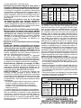
SPECIFICATIONS
Cat. No. Amps
No Load
RPM
Spindle
Thread
Size
Wheel
Size
6088-30
6088-31
6089-30
6089-31
120
120
120
120
15
15
15
15
5/8"-11
5/8"-11
5/8"-11
5/8"-11
7"/9"
7"/9"
7"/9"
7"/9"
•Support panels or any oversized workpiece
to minimize the risk of wheel pinching and
kickback. Large workpieces tend to sag under
their own weight. Supports must be placed under
the workpiece near the line of cut and near the
edge of the workpiece on both sides of the wheel.
•Use extra caution when making a “pocket
cut”intoexistingwallsor otherblindareas.
The protruding wheel may cut gas or water pipes,
electrical wiring or objects that can cause kickback.
SafetyWarningsSpecificforSandingOperations:
•Donotuseexcessivelyoversizedsandingdisc
paper.Followmanufacturersrecommendations,
whenselectingsandingpaper.Larger sanding
paper extending beyond the sanding pad presents
a laceration hazard and may cause snagging,
tearing of the disc or kickback.
Safety Warnings Specific for Wire Brushing
Operations:
•Beawarethatwirebristlesarethrownbythe
brushevenduringordinaryoperation.Donot
overstress the wires by applying excessive
loadtothebrush.The wire bristles can easily
penetrate light clothing and/or skin.
•Iftheuseofaguardisrecommendedforwire
brushing,donotallowanyinterferenceofthe
wirewheelorbrushwiththeguard.Wire wheel
or brush may expand in diameter due to work load
and centrifugal forces.
Maintainlabelsandnameplates.These carry
important information. If unreadable or missing,
contact a MILWAUKEE service facility for a free
replacement.
• WARNING: Some dust created by power sanding,
sawing, grinding, drilling, and other construction
activities contains chemicals known to cause
cancer, birth defects or other reproductive harm.
Some examples of these chemicals are:
• lead from lead-based paint
• crystalline silica from bricks and cement and
other masonry products, and
• arsenic and chromium from chemically-treated
lumber.
Your risk from these exposures varies, depending
on how often you do this type of work. To reduce
your exposure to these chemicals: work in a well
ventilated area, and work with approved safety
equipment, such as those dust masks that are spe-
cially designed to lter out microscopic particles.
edgesetc.Avoidbouncingandsnaggingthe
accessory. Corners, sharp edges or bouncing
have a tendency to snag the rotating accessory
and cause loss of control or kickback.
•Donotattachasawchainwoodcarvingbladeor
toothedsawblade.Such blades create frequent
kickback and loss of control.
Safety Warnings Specific for Grinding and
AbrasiveCutting-OffOperations:
•Useonlywheeltypesthatarerecommended
for your power tool and the specific guard
designed for the selected wheel. Wheels for
which the power tool was not designed cannot be
adequately guarded and are unsafe.
•Theguardmust be securelyattachedto the
powertoolandpositionedformaximumsafety,
so the least amount of wheel is exposed
towardstheoperator.The guard helps to protect
the operator from broken wheel fragments and,
accidental contact with wheel and sparks that could
ignite clothing.
NOTE The above warning may be omitted for
grinders or cut-off grinders with rated capacity of
less than 55 mm.
•Wheelsmustbeusedonlyforrecommended
applications.Forexample:donotgrindwiththe
sideofcut-offwheel.Abrasive cut-off wheels are
intended for peripheral grinding, side forces applied
to these wheels may cause them to shatter.
•Alwaysuseundamagedwheelflangesthatare
of correct size and shape for your selected
wheel.Proper wheel flanges support the wheel
thus reducing the possibility of wheel breakage.
Flanges for cut-off wheels may be different from
grinding wheel flanges.
•Donotuseworndownwheelsfromlargerpower
tools.Wheel intended for larger power tool is not
suitable for the higher speed of a smaller tool and
may burst.
AdditionalSafetyWarningsSpecificforAbrasive
Cutting-OffOperations:
•Donot"jam" thecut-offwheelorapplyexcessive
pressure.Donotattempttomakeanexcessive
depthofcut.Overstressing the wheel increases
the loading and susceptibility to twisting or binding
of the wheel in the cut and the possibility of kickback
or wheel breakage.
•Donotpositionyourbodyinlinewithandbehind
therotatingwheel.When the wheel, at the point
of operation, is moving away from your body, the
possible kickback may propel the spinning wheel
and the power tool directly at you.
•Whenwheelisbindingorwheninterruptinga
cutforanyreason,switchoffthepowertool
andholdthepowertoolmotionlessuntilthe
wheelcomestoacompletestop.Neverattempt
toremovethecut-offwheelfromthecutwhile
thewheelisinmotionotherwisekickbackmay
occur.Investigate and take corrective action to
eliminate the cause of wheel binding.
•Do not restart the cutting operation in the
workpiece.Letthewheelreachfullspeedand
carefullyreenterthecut.The wheel may bind,
walk up or kickback if the power tool is restarted
in the workpiece.

6
SYMBOLOGY
Double Insulated
Amperes
Volts
Alternating Current/Direct Current
No Load Revolutions
per Minute (RPM)
Underwriters Laboratories, Inc.
United States and Canada
Mexican Approvals Marking
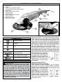
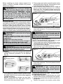
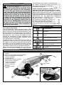
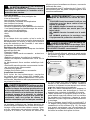
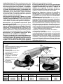
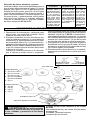
FUNCTIONAL DESCRIPTION
1. Rear handle
2. Trigger
3. Lock-on button (select models)
4. Handle release button (select models)
5. Side handle
6. Wheel guard (select models)
7. Grinding wheel
(select models)
8. Guard adjustment lock lever
(select models)
9. Spindle lock button
10. Side handle socket
8
(on bottom)
1
6
7
4
5
2
3
5
9
10
GROUNDING
WARNING Improperlyconnectingthe
groundingwirecanresultintheriskofelec-
tricshock.Checkwithaqualiedelectrician
ifyouareindoubtastowhethertheoutletis
properlygrounded.Donotmodifythe plug
provided with the tool. Never remove the
groundingprongfromtheplug.Donotuse
thetoolifthecordor plug is damaged. If
damaged,haveitrepairedbya MILWAUKEE
servicefacilitybeforeuse.Iftheplugwillnot
ttheoutlet,haveaproperoutletinstalledby
aqualiedelectrician.
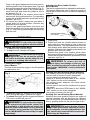
GroundedTools:ToolswithThreeProngPlugs
Tools marked “Grounding Required” have a three
wire cord and three prong grounding plug. The
plug must be connected to a properly grounded
outlet (See Figure A). If the tool should electrically
malfunction or break down, grounding provides a
low resistance path to carry electricity away from
the user, reducing the risk of electric shock.
The grounding prong in the plug is connected
through the green wire inside the cord to the
grounding system in the tool. The green wire in the
cord must be the only wire connected to the tool's
grounding system and must never be attached to
an electrically “live” terminal.
Your tool must be plugged into
an appropriate outlet, properly
installed and grounded in ac-
cordance with all codes and
ordinances. The plug and
outlet should look like those
in Figure A.
DoubleInsulatedTools:
ToolswithTwoProngPlugs
Tools marked “Double Insulated” do not require
grounding. They have a special double insulation
system which satises OSHA requirements and
complies with the applicable
standards of Underwriters
Laboratories, Inc., the Cana-
dian Standard Association
and the National Electrical
Code. Double Insulated tools
may be used in either of the
120 volt outlets shown in
Figures B and C.
Fig.B
Fig.C
Fig.A

7
ASSEMBLY
WARNING Toreducetheriskofinjury,
alwaysunplugtoolbeforechangingor re-
movingaccessories.Onlyuse accessories
specicallyrecommendedforthistool.Others
maybehazardous.
Grounded tools require a three wire extension
cord. Double insulated tools can use either a two
or three wire extension cord. As the distance from
the supply outlet increases, you must use a heavier
gauge extension cord. Using extension cords with
inadequately sized wire causes a serious drop in
voltage, resulting in loss of power and possible tool
damage. Refer to the table shown to determine the
required minimum wire size.
The smaller the gauge number of the wire, the
greater the capacity of the cord. For example, a 14
gauge cord can carry a higher current than a 16
gauge cord. When using more than one extension
cord to make up the total length, be sure each cord
contains at least the minimum wire size required.
If you are using one extension cord for more than
one tool, add the nameplate amperes and use the
sum to determine the required minimum wire size.
EXTENSION CORDS
READ AND SAVE ALL
INSTRUCTIONS FOR FUTURE USE.
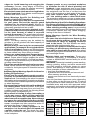
* Based on limiting the line voltage drop to ve volts at
150% of the rated amperes.
RecommendedMinimumWireGauge
ForExtensionCords*
ExtensionCordLength
Nameplate
Amperes
25' 50' 75' 100' 150'
0 - 2.0
2.1 - 3.4
3.5 - 5.0
5.1 - 7.0
7.1 - 12.0
12.1 - 16.0
16.1 - 20.0
18
18
18
18
16
14
12
18
18
18
16
14
12
10
18
18
16
14
12
10
--
18
16
14
12
10
--
--
16
14
12
12
--
--
--
GuidelinesforUsingExtensionCords
• If you are using an extension cord outdoors, be
sure it is marked with the sufx “W-A” (“W” in Cana-
da) to indicate that it is acceptable for outdoor use.
• Be sure your extension cord is properly wired
and in good electrical condition. Always replace a
damaged extension cord or have it repaired by a
qualied person before using it.
• Protect your extension cords from sharp objects,
excessive heat and damp or wet areas.
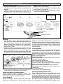
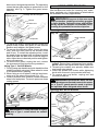
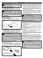
InstallingtheSideHandle
The side handle may be installed on the top of
the gear case or on either side of gear case for
right or left handed use. Position side handle in
the location which offers best control and guard
protection. For operating zones that provide
maximum protection for the operator, see Fig.
9. To install, thread side handle into side handle
socket on desired side of gear case and tighten
securely.
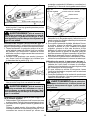
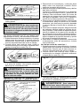
Installing,Adjusting,andRemovingtheGuard
The guard must be used when using the tool as a
grinder. The guard should be removed when using
tool as a sander.
1. To install the guard, unplug the tool and place
it upside down on a level surface. Remove any
accessories from the spindle.
Line up the tabs with the tab slots (Fig. 2). Then
press the guard down onto the tool.
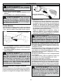
RemovingandReplacingQuik-Lok
®
Cords
(SelectModels)
MILWAUKEE's exclusive Quik-Lok
®
Cords provide
instant eld replacement or substitution.
1. To remove the Quik-Lok
®
Cord, turn the cord nut
1/4 turn to the left and pull it out.
2. To replace the Quik-Lok
®
Cord, align the connec-
tor keyways and push the connector in as far as it
will go. Turn the cord nut 1/4 turn to the right to lock.
Fig.1
WARNING Toreduce the risk of in-
jurywhengrinding,ALWAYSusetheproper
guard.ALWAYS properly install the guard.
Press in the guard adjustment lock lever and rotate
the guard to one of the detent slots. The lock lever
must engage with one of the detents (Fig. 3).
Fig.2
Guard adjustment
lock lever
Tab slot
Tab slot
Tab slot
Fig.3
Guard adjustment
lock lever
Guard
Lock
lever
must
engage
one of
detents

8
OPERATION
Press in the guard adjustment lock lever and ro-
tate the guard to one of the detent slots. The lock
lever must engage with one of the detents (Fig. 3).
2. To adjust the guard, press in the guard adjust-
ment lock lever and rotate the guard to one of
the detents (Fig. 3).
Position the guard in the location which offers
best control and guard protection. For operating
zones that provide maximum protection for the
operator, see Fig. 9.
3. To remove the guard, unplug tool and place it
upside down on a level surface. Remove any
accessories from spindle.
Press in the guard adjustment lock lever and
rotate the guard to line up the tabs with the slots
(Fig. 2). Then lift the guard straight up and away
from the tool.
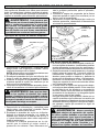
StartingandStoppingtheMotor
1. To start the tool, pull the trigger.
2. To stop the tool, release the trigger.
1. To lock the trigger on, hold the lock-on button in
while pulling the trigger. Release the trigger.
2. To unlock the trigger, pull the trigger and release.
The lock-on button will pop out.
LockingtheTrigger
SelectModels
The lock button holds the trigger in the ON position
for continuous use.
WARNING Toreducetheriskofinjury,
wearsafetygogglesorglasseswithsideshields.
WARNING
Toreducetheriskofinjury
ordamagetothetool,donotusethespindle
lockbuttontostopthespindlewhilethetool
isinuseoriscoastingaftershut-off.
1. Unplug tool.
2. Press and hold the handle release button in
and rotate the rear handle to one of the nine
handle positions. The adjustable handle feature
has detents which allow the handle to snap into
position. Make sure the handle snaps rmly into
position and does not rotate.
Position the guard in the location which offers
best control and guard protection. For operating
zones that provide maximum protection for the
operator, see Fig. 9.
AdjustingtheRearHandlePosition
SelectModels
This tool is equipped with an adjustable rear handle.
This feature allows the user to adjust the angle of
the handle to nine positions for optimum operating
positions.
Handle releas button
(on bottom)
Fig.5
WARNING
Toreducetheriskofinjury,
donotoperatetoolwithhandlereleasebut-
tonpressedinorwithhandlenotlockedinto
position.Ifthehandledoesnotlocksecurely
intoposition,donotoperatetool.Returnthe
tool to a MILWAUKEEservicefacilityforrepair
immediately.
SandingDiscandGrindingWheelSelection
Use sanding discs and grinding wheels that are:
• correct size as written on tool's nameplate
• correct wheel type and grit for the job
• rated at or above the RPM listed in the “WARN-
ING” section on the tool's nameplate
Use backing pads, adapters, and other acces-
sories that are:
•correct size for tool and for sanding disc or grind-
ing wheel
•rated at or above the RPM listed in the “WARN-
ING” section on the tool's nameplate
•the proper accessory for the job
SandingDiscandGrindingWheelMaterial
Sanding discs and grinding wheels are made of
various materials and are designed for different
jobs. Be sure that you choose the proper sanding
disc or grinding wheel for the job you plan to do.
WARNING Toreducetheriskof
personalinjuryanddamagetothetool,use
ONLYaccessoriesratedatorabovetheRPM
listedonthe“WARNING”sectionofthetool's
nameplate.
WARNING Toreducetheriskofinjury,
alwaysunplugtoolbeforeattachingorremov-
ingaccessoriesormakingadjustments.Use
onlyspecicallyrecommendedaccessories.
Othersmaybehazardous.
Fig.4
Lock-on button

9
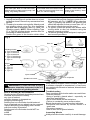
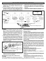
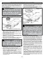
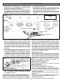
InstallingSandingDiscs
1. Unplug tool and place it upside down on a level
surface as shown. Remove any accessories from
spindle.
2. Thread nylon washer onto spindle. Attach
backing pad and sanding disc using Fig. 6
to determine type and order of assembly.
Fig.6
Spindle lock button
Spindle
Backing
pads
A. Polypropylene
B. Spiral
C. Rubber
D. Phenolic
Disc nut
Sanding
disc
Nylon washer
Rubber
pad
Type 27
ange
Flap disk Flap disk with hub
B
C DA
Disc nut position
USING SANDING DISCS
NOTE:When installing ap disc without hub,
position disc nut as shown.
3. To tighten, press the spindle lock button while
turning disc nut clockwise.
4. To remove sanding disc and backing pad, unplug
tool and reverse procedure.
RemovingWeldsorHammerMarks
When removing welds or hammer marks, limit
coarse sanding to the immediate area. Use suc-
cessively ner grits to smooth surface.
CrossSanding
When finishing a surface that has been pre-
pared by a coarse disc or wheel, sand at right
3. Use long, sweeping, side to side strokes, advanc-
ing forward to produce the desired nish.
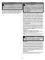
Sanding
1. Use a clamp, vise or other practical means to
hold your work, freeing both hands to control your
tool. Firmly grasp rear handle and side handle
before starting and while tool is in operation.
Allow sanding disc to come to full speed before
beginning to sand.
2. Hold tool at 5° to 15° angle as shown to ensure
proper sanding pressure and control (Fig. 7). Too
great an angle will result in too much pressure
and could cause excessive wear to the disc and
workpiece. Too small an angle will reduce control.
Hold at a 5° to 15° angle
Fig.7
For best results use only
this portion of disc
angles to the strokes made by the coarser disc.
Finishing marks left from previous sanding are eas-
ily seen and removed for a uniform nish. Failure
to cross sand when changing from a coarse disc to
a nishing disc may result in deep scratches and
circular marks.
SelectingSandingDiscs&Grit
Refer to the table below to select the correct type
of sanding disc for your job. Generally, use 16, 24
or 36 grit for heavy stock removal; 50, 60 or 80 grit
for medium stock removal and 120 grit for nishing.
Always begin with a coarse grit, using successively
ner grits to obtain the desired nish. See Catalog
for a complete list of MILWAUKEE sanding discs.
FinishingMetal
Constantly move across the surface. Work faster on
curved surfaces where contact areas are smaller
and pressure is greater. Flat areas may appear at
the end of the stroke when pressure is too heavy.
Ease up on pressure at end of each stroke and
when reversing strokes.
Troubleshooting
Deep scratches and circular marks can result from:
• Using too coarse a grit
• Using a partially glazed disc
• Dirt or loose metal on the workpiece
• Failure to sand across the grain when changing
from coarse to nishing discs
Bluish discoloration of metal surface indicates:
• Excessive heat caused by circular motion in a
small area
• Excessive pressure
• Use of worn out or glazed discs

10
AluminumOxide AluminumZirconiaBi-Cut Ceramic
For fast cutting, general purpose discs for
most metal jobs. Best for cold-rolled steel,
stainless steel or metals requiring tough, fast
cutting, long lasting abrasives.
Unique grit pattern is arranged in clus-
ters for faster stock removal and clean-
ing. Ideal for removing paint from cars,
boats, etc. without clogging.
Lasts up to 3 times longer than
aluminum oxide discs. For
general metal working. Ideal
for tough jobs.
InstallingGrindingWheels
1. Unplug tool and place it upside down on a level
surface as shown. Remove any accessories from
spindle.
2. Thread nylon washer onto spindle. Attach guard
and grinding wheel using Fig. 8 to determine
type and order of assembly (See Fig. 2 and 3 for
attaching guard).NOTE:When installing Type
27 or Type 29 grinding wheels, position disc nut
according to wheel thickness.
Position the guard in the location which offers
USING GRINDING AND CUT-OFF WHEELS
best control and guard protection. For operat-
ing zones that provide maximum protection for
the operator, see Fig. 9. NOTE: When selecting
Type 11 grinding cup wheels, the guard’s skirt
should be adjusted so that no more than 1/8" of
the wheel extends beyond the guard.
3. To tighten, press the spindle lock button while
turning wheel or disc nut clockwise using the
spanner wrench provided.
4. To remove grinding wheel and guard, unplug tool
and reverse procedure.
Grinding wheels
A. Type 28 with hub
B. Type 27 with hub
Type 29 with hub
C. Type 27 with ange
Type 29 with ange
D. Type 11
Guard
E. Type 28
F. Type 27
G. Type 27
H. Type 11
Fig.8
Spindle
Disc nut
Nylon washer
Type 27
ange
Type 11
ange
B
C
D
A
Spindle lock button
F G
H
E
1/4" thick
wheels
1/8" thick or
less wheels
Disc nut position
B
CareofGrinding&Cut-OffWheels
Grinding and cut-off wheels should be protected from:
• wetness and extreme humidity
• any type of solvent
• extreme changes in temperature
• dropping and bumping
Grinding and cut-off wheels should bestored:
• in an organized way so wheels can be removed
without disturbing or damaging other wheels
• with their safety information
Grinding and cut-off wheels should NOT be:
• dropped
• rolled
• bumped
WARNING Toreducetheriskofinjury,
theoperatorshouldbeinstructedintheuse,
careandprotectionofgrindingwheels.
If any wheel is dropped, rolled, bumped, subjected
to extreme changes in temperature, or has come
into contact with solvents or wetness, discard wheel
immediately.
Troubleshooting
Deep scratches and circular marks can result from:
• Uneven pressure
• Using a partially glazed wheel - especially on
aluminum applications
• Dirt or loose metal on the workpiece
• Failure to constantly move across surface
Bluish discoloration of metal surface indicates:
• Excessive heat caused by circular motion in a
small area
• Excessive pressure
• Use of worn out or glazed wheels
InspectingWheels
Always handle wheels carefully to avoid damage.

11
WARNING OnlyusewheelswithMaxi-
mumSafeOperatingSpeedratedatorabove
theRPMlistedonthe“WARNING” section
ofthetool'snameplate.Thisspeedisbased
onthestrengthofthewheel,allowingfora
reasonablemeasureofsafety.Itisnotmeant
toimplyabestormostefcientoperating
speed. Do not exceed the Maximum Safe
OperatingSpeed.
Before installing any wheel, always inspect it for
cracks. If wheel is cracked, discard it to prevent
others from using it.
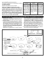
Grinding
1. Depending on your job, position the guard to
provide maximum protection for the operator
(Fig. 9).
SelectingWheels
Grinding is the cutting action of thousands of abra-
sive grains on the face of a grinding wheel. When
grinding metals such as steel and iron, choose an
aluminum oxide grinding wheel. Select a silicon
carbide grinding wheel for stone and concrete. Use
cotton reinforced wheels for non-ferrous metals.
Type 27 reinforced 1/8" cut-off wheels are suited for
small cut-off and shallow notching operations only.
2. If you have just installed a grinding wheel or are
just beginning a period of work, test the wheel
by letting it spin for one minute before applying
it to the workpiece.
NOTE: Out-of-balance wheels can mar work-
piece, damage the tool, and cause stress to
wheel that may cause wheel failure.
WARNING Toreducetheriskofinjury
whengrinding:
•ALWAYSholdthetoolrmlywithbothhands
usingthehandlesprovided;beforeanddur-
inggrinding
•NEVERallowthewheeltobind
•NEVERuseawheelthathasbeendropped
•NEVERbanggrindingwheelontowork
•NEVERgrindwithoutpropersafetyequipment
WARNING Toreducetheriskofinjury
whengrinding,ALWAYSusetheproperguard.
ALWAYSproperlyinstalltheguard.
3. Firmly grasp rear handle and side handle before
starting and while using tool. Allow wheel to come
to full speed before starting to grind.
4. When grinding, hold tool at a 5
o
to 15
o
angle as
shown, using constant pressure for a uniform
nish (Fig. 10). Too great an angle causes too
much pressure on small areas which may gouge
or burn work surface.
Fig.9
1
Operator's Zones
1
1
1
UsingType27Cut-OffWheels
Type 27 cut-off wheels are only suited for small
cut-off and shallow notching operations.
1. Firmly grasp rear handle and side handle before
starting and while using tool. Allow wheel to come
to full speed before starting.
2. When using a cut-off wheel, hold tool as shown,
using only the edge of the wheel (Fig. 11).
Fig.11
Fig.10
Hold at a 5° to 15° angle
5. Control pressure and surface contact between
wheel and workpiece. Too much pressure slows
cutting speed.
WARNING AType 27guard mustbe
installedwhenusingaType27cut-offwheelto
providemaximumprotectionfortheoperator
ifthewheelshouldbreak.
3. Control pressure and surface contact between
wheel and workpiece. Too much pressure slows
cutting speed.
InstallingandRemovingType1GuardAssem-
blyandAdjustingShoe
1. Unplug tool and place it upside down on a level
surface. Remove any accessories from spindle.
2. Loosen the guard screw and slip the guard over
the spindle.
Position the guard in the location which offers
WARNING AType 1 guard must be
installedwhenusingaType1cut-offwheelto
providemaximumprotectionfortheoperator
ifthewheelshouldbreak.

12
best control and guard protection. For operating
zones that provide maximum protection for the
operator, see Fig. 9. Tighten the guard screw
securely.
UsingType1Cut-OffWheels
1. Firmly grasp rear handle and side handle before
starting and while using tool. Allow wheel to come
to full speed before starting.
2. When using a cut-off wheel, hold tool as shown,
using only the edge of the wheel (Fig. 13).
3. Control pressure and surface contact between
wheel and workpiece. Too much pressure slows
cutting speed.
Fig.13
3. To adjust the guard, unplug the tool, loosen the
guard screw, rotate the guard to the desired
position and retighten the guard screw.
4. To remove the adjusting shoe, loosen the wing
nuts, slide the shoe over to the access holes
and lift out. To install the adjusting shoe, insert
the head of the carriage bolts into guard access
holes and slide the shoe over to the far edge of
slots. Adjust shoe to desired position and tighten
wing nuts securely.
5. To remove the guard, unplug the tool, remove
the accessories and reverse the procedure.
Fig.12
Guard
Guard screw
Adjusting shoe
Carriage bolt and wingnut
Spindle
WARNING Toreducetheriskofinjury,
neveruseaType1cut-offwheelforsurface
grinding.
SelectingWireBrushes
Wire brushes are useful for removing rust, scale,
burrs, weld slag, etc. A wide variety of wire brushes
are available for many applications.
USING WIRE BRUSHES
InstallingWireCupBrushes
1. Unplug tool and place it upside down on a level
surface. Remove any accessories from spindle.
NOTE:Never use a guard with a wire cup brush.
2. Thread nylon washer onto spindle. Attach wire
cup brush onto spindle.
3. Press the spindle lock button while tightening
brush with a wrench (not provided with tool).
4. To remove wire cup brush, unplug tool and
reverse procedure.
Spindle lock button
Fig.14
Wire cup brush
Nylon washer
Spindle
WARNING Everyoneintheareamust
wearprotectiveclothingandsafetygoggles
orface shields.Fatigued wiresand residue
willyoffthebrushwithconsiderableforce,
causingthepotentialforseriousinjuries.
WARNING Becausethewiresonwire
wheelbrushesaredirectedtowardstheopera-
tor,aType27guardmustbeusedtoprotect
theoperatorwhenfatiguedwiresbreak.
InstallingWireWheelBrushes
Wire wheel brush
Fig.15
Guard
Nylon
washer
Spindle
Spindle
lock
button

13
ACCESSORIES
For a complete listing of accessories refer to your
MILWAUKEE Electric Tool catalog or go on-line
to www.milwaukeetool.com. To obtain a catalog,
contact your local distributor or a service center.
WARNINGToreducetheriskofinjury,
always unplug the tool before attaching or
removingaccessories.Useonlyspecically
recommendedaccessories. Othersmaybe
hazardous.
MaintainingTools
Keep your tool in good repair by adopting a regular
maintenance program. Before use, examine the
general condition of your tool. Inspect guards,
switches, tool cord set and extension cord for
damage. Check for loose screws, misalignment,
binding of moving parts, improper mounting, bro-
ken parts and any other condition that may affect
its safe operation. If abnormal noise or vibration
occurs, turn the tool off immediately and have the
problem corrected before further use. Do not use a
damaged tool. Tag damaged tools “DO NOT USE”
until repaired (see “Repairs”).
Under normal conditions, relubrication is not neces-
sary until the motor brushes need to be replaced.
After six months to one year, depending on use,
return your tool to the nearest MILWAUKEE service
facility for the following:
• Lubrication
• Brush inspection and replacement
• Mechanical inspection and cleaning (gears, spin-
dles, bearings, housing, etc.)
• Electrical inspection (switch, cord, armature, etc.)
• Testing to assure proper mechanical and electrical
operation
WARNINGToreducetheriskofinjury,
electricshockanddamagetothetool,never
immerseyourtoolinliquidorallowaliquid
toowinsidethetool.
MAINTENANCE
WARNINGToreducetheriskofinjury,
always unplugyourtoolbeforeperforming
anymaintenance.Neverdisassemblethetool
ortrytodoanyrewiringonthetool’selectrical
system.Contacta MILWAUKEEservicefacility
forALLrepairs.
Cleaning
Clean dust and debris from vents. Keep the tool
handles clean, dry and free of oil or grease. Use
only mild soap and a damp cloth to clean your
tool since certain cleaning agents and solvents
are harmful to plastics and other insulated parts.
Some of these include: gasoline, turpentine, lacquer
thinner, paint thinner, chlorinated cleaning solvents,
ammonia and household detergents containing
ammonia. Never use ammable or combustible
solvents around tools.
Repairs
If your tool is damaged, return the entire tool to the
nearest service center.
UsingWireBrushes
1. Do not wear loose clothing when using wire
brushes. The wires may catch on loose clothing
and pull the clothing into the moving parts.
2. Firmly grasp rear handle and side handle before
starting and while using tool. Always test the wire
brush for balance and loose or damaged wires
by running tool at no load speed for at least one
minute before applying it to your work.
3. When applying brush to work, avoid using too
much pressure. This causes over-bending of
wires and heat build-up resulting in premature wire
breakage, rapid dulling and reduced brush life.
Instead of using more pressure, try a wire
wheel brush with more aggressive cutting ac-
tion (increased wire size, decreased wire length
or different brush type, i.e. knot type instead of
crimped wire type).
1. Unplug tool and place it upside down on a level
surface. Remove any accessories from spindle.
2. Thread nylon washer onto spindle. Attach guard
and wire wheel brush onto spindle (see Fig. 2
and 3 for attaching guard).
Position the guard in the location which offers
best control and guard protection. For operating
zones that provide maximum protection for the
operator, see Fig. 9.
3. Press the spindle lock button while tightening
brush with a wrench (not provided with tool).
4. To remove wire wheel brush and guard, unplug
tool and reverse procedure.
WARNING Never exceed Maximum
SafeOperatingSpeedofthebrush.Donotuse
adamagedbrushoronewhichisfunctioning
improperly(throwingwires,out-of-balance,
etc.). These conditions increase the pos-
sibilityoffurtherbrushfailureandpossible
injury.Discardandreplacedamagedbrushes
immediately.

14
TECHTRONIC INDUSTRIES' warranty is for 5 year since the original purchase date.
This warranty card covers any defect in material and workmanship on this Power Tool.
To make this warranty valid, present this warranty card, sealed/stamped by the distributor or store where you pur-
chased the product, to the Authorized Service Center (ASC). Or, if this card has not been sealed/stamped, present the
original proof of purchase to the ASC.
Call toll-free 1 800 832 1949 to nd the nearest ASC, for service, parts, accessories or components.
Proceduretomakethiswarrantyvalid
Take the product to the ASC, along with the warranty card sealed/stamped by the distributor or store where you pur-
chased the product, and there any faulty piece or component will be replaced without cost for you. We will cover all
freight costs relative with this warranty process.
Exceptions
This warranty is not valid in the following situations:
a) When the product is used in a different manners from the end-user guide or instruction manual.
b) When the conditions of use are not normal.
c) When the product was modied or repaired by people not authorized by TECHTRONIC INDUSTRIES.
Note: If cord set is damaged, it should be replaced by an Authorized Service Center to avoid electric risks.
SERVICE AND ATTENTION CENTER
Av Presidente Mazarik 29 Piso 7, 11570 Chapultepec Morales
Miguel Hidalgo, Distrito Federal, Mexico
Ph. 52 55 4160-3547
IMPORTED AND COMMERCIALIZED BY:
TECHTRONIC INDUSTRIES MEXICO, .S.A. DE C.V.
Av Presidente Mazarik 29 Piso 7, 11570 Chapultepec Morales
Miguel Hidalgo, Distrito Federal, Mexico
LIMITED WARRANTY - USA AND CANADA
LIMITED WARRANTY - MEXICO, CENTRAL AMERICA AND CARIBBEAN
Model:
DateofPurchase:
DistributororStoreStamp:
Every MILWAUKEE power tool (including cordless product – tool, battery pack(s) - see separate & distinct
CORDLESS BATTERY PACK LIMITED WARRANTY statements & battery charger and Work Lights*) is war-
ranted to the original purchaser only to be free from defects in material and workmanship. Subject to certain
exceptions, MILWAUKEE will repair or replace any part on an electric power tool which, after examination, is
determined by MILWAUKEE to be defective in material or workmanship for a period of ve (5) years* after the
date of purchase unless otherwise noted. Return of the power tool to a MILWAUKEE factory Service Center
location or MILWAUKEE Authorized Service Station, freight prepaid and insured, is required. A copy of the
proof of purchase should be included with the return product. This warranty does not apply to damage that
MILWAUKEE determines to be from repairs made or attempted by anyone other than MILWAUKEE authorized
personnel, misuse, alterations, abuse, normal wear and tear, lack of maintenance, or accidents.
*The warranty period for, Job Site Radios, M12™ Power Port, M18™ Power Source, and Trade Titan™ Indus-
trial Work Carts is one (1) year from the date of purchase. The warranty period for a LED Work Light and LED
Upgrade Bulb is a limited LIFETIME warranty to the original purchaser only, if during normal use the LED bulb
fails the Work Light or Upgrade Bulb will be replaced free of charge.
*This warranty does not cover Air Nailers & Stapler, Airless Paint Sprayer, Cordless Battery Packs, Gasoline
Driven Portable Power Generators, Hand Tools, Hoist – Electric, Lever & Hand Chain, M12™ Heated Jackets,
Reconditioned product and Test & Measurement products. There are separate and distinct warranties avail-
able for these products.
Warranty Registration is not necessary to obtain the applicable warranty on a MILWAUKEE power tool product.
The manufacturing date of the product will be used to determine the warranty period if no proof of purchase is
provided at the time warranty service is requested.
ACCEPTANCE OF THE EXCLUSIVE REPAIR AND REPLACEMENT REMEDIES DESCRIBED HEREIN IS A
CONDITION OF THE CONTRACT FOR THE PURCHASE OF EVERY MILWAUKEE PRODUCT. IF YOU DO NOT
AGREE TO THIS CONDITION, YOU SHOULD NOT PURCHASE THE PRODUCT. IN NO EVENT SHALL MIL-
WAUKEE BE LIABLE FOR ANY INCIDENTAL, SPECIAL, CONSEQUENTIAL OR PUNITIVE DAMAGES, OR FOR
ANY COSTS, ATTORNEY FEES, EXPENSES, LOSSES OR DELAYS ALLEGED TO BE AS A CONSEQUENCE
OF ANY DAMAGE TO, FAILURE OF, OR DEFECT IN ANY PRODUCT INCLUDING, BUT NOT LIMITED TO, ANY
CLAIMS FOR LOSS OF PROFITS. SOME STATES DO NOT ALLOW THE EXCLUSION OR LIMITATION OF IN-
CIDENTAL OR CONSEQUENTIAL DAMAGES, SO THE ABOVE LIMITATION OR EXCLUSION MAY NOT APPLY
TO YOU. THIS WARRANTY IS EXCLUSIVE AND IN LIEU OF ALL OTHER EXPRESS WARRANTIES, WRITTEN
OR ORAL. TO THE EXTENT PERMITTED BY LAW, MILWAUKEE DISCLAIMS ANY IMPLIED WARRANTIES,
INCLUDING WITHOUT LIMITATION ANY IMPLIED WARRANTY OF MERCHANTABILITY OR FITNESS FOR A
PARTICULAR USE OR PURPOSE; TO THE EXTENT SUCH DISCLAIMER IS NOT PERMITTED BY LAW, SUCH
IMPLIED WARRANTIES ARE LIMITED TO THE DURATION OF THE APPLICABLE EXPRESS WARRANTY AS
DESCRIBED ABOVE. SOME STATES DO NOT ALLOW LIMITATIONS ON HOW LONG AN IMPLIED WARRANTY
LASTS, SO THE ABOVE LIMITATION MAY NOT APPLY TO YOU, THIS WARRANTY GIVES YOU SPECIFIC
LEGAL RIGHTS, AND YOU MAY ALSO HAVE OTHER RIGHTS WHICH VARY FROM STATE TO STATE.
This warranty applies to product sold in the U.S.A. and Canada only.
Please consult the ‘Service Center Search’ in the Parts & Service section of MILWAUKEE’s website www.mil-
waukeetool.com or call 1.800.SAWDUST(1.800.729.3878) to locate your nearest service facility for warranty
and non-warranty service on a Milwaukee electric power tool.
Page is loading ...
Page is loading ...
Page is loading ...
Page is loading ...
Page is loading ...
Page is loading ...
Page is loading ...
Page is loading ...
Page is loading ...
Page is loading ...
Page is loading ...
Page is loading ...
Page is loading ...
Page is loading ...
Page is loading ...
Page is loading ...
Page is loading ...
Page is loading ...
Page is loading ...
Page is loading ...
Page is loading ...
Page is loading ...
Page is loading ...
Page is loading ...
Page is loading ...
Page is loading ...
Page is loading ...
Page is loading ...
Page is loading ...

MILWAUKEEELECTRICTOOLCORPORATION
13135WestLisbonRoad•Brookeld,Wisconsin,U.S.A.53005
58-14-5121d2 07/12 Printed in China
961075022-03( )
UNITED STATES
MILWAUKEEService
CANADA - ServiceMILWAUKEE
MILWAUKEE prides itself in producing a premium
quality product that is NothiNg But heavy Duty
®
.
Your satisfaction with our products is very impor-
tant to us!
If you encounter any problems with the operation
of this tool, or you would like to locate the factory
Service/Sales Support Branch or authorized ser-
vice station nearest you, please call...
1.800.268.4015
Monday – Friday 7:00 – 4:30 CST
fax: 866.285.9049
MilwaukeeElectricTool(Canada)Ltd
140 Fernstaff Court, Unit 4 18129 111 Avenue NW
Vaughan, ON L4K 3L8 Edmonton, AB T5S 2P2
Additionally, we have a nationwide network of
authorized Distributors ready to assist you with your
tool and accessory needs. Call 1.800.268.4015 to
nd the names and addresses of the closest re-
tailers or consult “Where to buy” on our Web site
www.milwaukeetool.com
MILWAUKEE est er de proposer un produit de
première qualité NothiNg But heavy Duty
®
. Votre
satisfaction est ce qui compte le plus!
En cas de problèmes d’utilisation de l’outil ou pour
localiser le centre de service/ventes ou le centre
d’entretien le plus proche, appelez le...
1.800.268.4015
Lundi – Vendredi 7:00 – 4:30 CST
fax: 866.285.9049
MilwaukeeElectricTool(Canada)Ltd
140 Fernstaff Court, Unit 4 18129 111 Avenue NW
Vaughan, ON L4K 3L8 Edmonton, AB T5S 2P2
Notre réseau national de distributeurs agréés se
tient à votre disposition pour fournir l’aide tech-
nique, l’outillage et les accessoires nécessaires.
Composez le 1.800.268.4015 pour obtenir les
noms et adresses des revendeurs les plus proches
ou bien consultez la section «Où acheter» sur notre
site web à l’adresse www.milwaukeetool.com
CENTRO DE ATENCIÓN A CLIENTES
Av Presidente Mazarik 29 Piso 7
11570 Chapultepec Morales
Miguel Hidalgo, Distrito Federal, Mexico
Telefono 52 55 4160-3547
e-mail: [email protected]
Adicionalmente, tenemos una red nacional de
distribuidores autorizados listos para ayudarle con
su herramienta y sus accesorios. Por favor, llame
al 01 800 832 1949 para obtener los nombres y
direcciones de los más cercanos a usted, o con-
sulte la sección ‘Where to buy’ (Dónde comprar)
de nuestro sitio web en
www.ttigroupmexico.com
MILWAUKEE prides itself in producing a premium
quality product that is NothiNg But heavy Duty
®
.
Your satisfaction with our products is very impor-
tant to us! If you encounter any problems with the
operation of this tool, or you would like to locate the
factory Service/Sales Support Branch or authorized
service station nearest you, please call...
Additionally, we have a nationwide network of
authorized Distributors ready to assist you with
your tool and accessory needs. Check your “Yellow
Pages” phone directory under “Tools-Electric” for
the names & addresses of those nearest you or see
the 'Where To Buy' section of our website.
1-800-SAWDUST
(1.800.729.3878)
Monday-Friday
7:00 AM - 6:30 PM
Central Time
or visit our website at
www.milwaukeetool.com
For service information, use the 'Service Center
Search' icon found in the 'Parts & Service' section.
Contact our Corporate After Sales Service
TechnicalSupportabout...
•Technical Questions
•Service/Repair Questions
•Warranty
call:1-800-SAWDUST
fax:1.800.638.9582
email:[email protected]
Registeryourtoolonlineat
www.milwaukeetool.comand...
• receive important notications regarding
your purchase
• ensure that your tool is protected under the
warranty
• become a heavy Duty club member
MEXICO - Soporte de Servicio MILWAUKEE
Registresuherramientaenlínea,en
www.ttigroupmexico.comy...
• reciba importantes avisos sobre su compra
• asegúrese de que su herramienta esté prote-
gida por la garantía
• conviértase en integrante de Heavy Duty
-
 1
1
-
 2
2
-
 3
3
-
 4
4
-
 5
5
-
 6
6
-
 7
7
-
 8
8
-
 9
9
-
 10
10
-
 11
11
-
 12
12
-
 13
13
-
 14
14
-
 15
15
-
 16
16
-
 17
17
-
 18
18
-
 19
19
-
 20
20
-
 21
21
-
 22
22
-
 23
23
-
 24
24
-
 25
25
-
 26
26
-
 27
27
-
 28
28
-
 29
29
-
 30
30
-
 31
31
-
 32
32
-
 33
33
-
 34
34
-
 35
35
-
 36
36
-
 37
37
-
 38
38
-
 39
39
-
 40
40
-
 41
41
-
 42
42
-
 43
43
-
 44
44


Milwaukee 6088-30 User manual
- Category
- Power tools
- Type
- User manual
Ask a question and I''ll find the answer in the document
Finding information in a document is now easier with AI
in other languages
- français: Milwaukee 6088-30 Manuel utilisateur
- español: Milwaukee 6088-30 Manual de usuario
Related papers
Other documents
-
Makita SA7000C Owner's manual
-
Ryobi PSBCK06K Owner's manual
-
-
Ryobi PSBCS02 User manual
-
DeWalt DWE4214 Installation guide
-
Black & Decker TV800 User manual
-
MasterForce V User manual
-
Makita GA5020Y User guide
-
Stanley FMC761 Original Instructions Manual
-