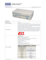
Tripp Lite B060-032 Owner's manual
- Category
- KVM switches
- Type
- Owner's manual
This manual is also suitable for

Owner’s Manual
NetDirector
™
Matrix KVM Switch
32 Port (4 User)
Model #: B060-032
Tripp Lite World Headquarters
1111 W. 35th Street, Chicago, IL 60609 USA
(773) 869-1234, www.tripplite.com
Note: Follow these instructions and operating procedures to ensure correct performance and to prevent damage
to this unit or to its connected devices.
Copyright © 2007 Tripp Lite. All rights reserved. All trademarks are the property of their respective owners.
The policy of Tripp Lite is one of continuous improvement. Specifications are subject to change without notice.
WARRANTY
REGISTRATION:
register online today for
a chance to win a FREE
Tripp Lite product—
www.tripplite.com/warranty
200701032 93-2287 B060-032 OM Update.qxd 1/15/2007 11:53 AM Page 1

2
Introduction ......................................................3
Introduces you to the B060-032 System. Its purpose,
features and benefits are presented; its front and back
panel components are explained; and the modules used
to connect to it are described.
Features ......................................................................3
Hardware Requirements ............................................3
Console ................................................................3
Computers ............................................................3
Cables ....................................................................3
B060-032 Front View ................................................4
B060-032 Rear View ..................................................5
Console Interface Modules ........................................5
Console Interface Modules Front View ....................5
Console Interface Modules Rear View ......................6
Installation ........................................................7
Takes you through the B060-032’s installation
procedures from a basic single stage hookup to a complete
daisy chained plus cascaded installation.
Overview ....................................................................7
Before you Begin ......................................................7
Single Stage Installation ............................................8
Multilevel Installations..............................................10
Overview ............................................................10
Daisy Chaining ....................................................10
Cascading ............................................................11
Protocol Interface Cascading ........................12
Physical Interface Cascading..........................13
Daisy Chaining Plus Cascading Expansion ..............15
Protocol Interface Expansion ..............................15
Physical Interface Expansion ..............................16
Topology Considerations ........................................17
Basic Operations ......................................................17
Hot Plugging ........................................................17
Powering Off and Restarting ..............................17
Port Selection ......................................................17
Port ID Numbering ............................................17
Single Stage and Daisy Chained Installations ....17
Cascaded Protocol Interface Installations............18
Cascaded Physical Interface Installations............18
User Management and Security ..........................18
OSD Operation ................................................19
Provides detailed information for configuring and
controlling your installation using the B060-032’s
intuitive, mouse-driven OSD (On Screen Display) menus.
OSD Overview ........................................................19
OSD Main Screen Headings ....................................20
OSD Navigation ......................................................20
OSD Functions ........................................................20
F1 GOTO: ............................................................21
F2 LIST: ..............................................................21
F3 SET: ..............................................................21
F4 ADM: ............................................................23
F5 SKP: ..............................................................25
F6 BRC: ..............................................................25
F7 SCAN: ............................................................25
F8 LOUT: ............................................................26
Cascaded OSD Operation ........................................26
Hotkey Operation ............................................27
Explains the concepts and procedures used in controlling
the B060-032 from the keyboard.
Hotkey Port Control ................................................27
Invoking Hotkey Mode ......................................27
Selecting the Active Port ....................................27
Auto Scanning ....................................................28
Skip Mode ..........................................................29
Hotkey Beeper Control ............................................29
Hotkey Summary Table ......................................29
Multiplatform Support ....................................30
Sun Keyboard Emulation ....................................30
Mac Keyboard Emulation ..................................30
The Firmware Upgrade Utility........................31
Explains how to upgrade the B060-032’s firmware with
the latest available versions.
Introduction ..............................................................31
Purpose ................................................................31
Before You Begin ................................................31
Performing the Upgrade ..........................................32
Starting the Upgrade ..........................................32
Upgrade Failure ..................................................32
Appendix..........................................................33
Provides technical and other important information
regarding the B060-032.
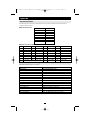
Connection Tables ....................................................33
B060-032 Daisy Chain ........................................33
B060-032 Cascade to Tripp Lite B007-008 ............33
OSD Factory Default Settings ................................33
Clear Login Information ..........................................34
Specifications ................................................35
B060-032 ............................................................35
Console Interface Modules ................................35
Server Interface Modules ....................................35
Troubleshooting ............................................36
FCC Radio/TV Interference Notice ....................36
Warranty Registration ....................................36
Warranty ..............................................................36
• 1 B060-032 KVM Switch
• 1 Power Cord
• 1 2-ft. Daisy Chain Cable
• 1 CD with Owner’s Manual and Quick Start Guide
This package should consist of:
Table of Contents
200701032 93-2287 B060-032 OM Update.qxd 1/15/2007 11:53 AM Page 2

3
Introduction
Features
• Four consoles independently and simultaneously control up to 32 directly connected computers
• Daisy chain up to 7 additional units
• Cascade up to 32 compatible KVM switches from each station on the chain
• Control up to 4,096 computers on a daisy chained/cascaded installation
• Compact design - RJ-45 connectors allow rack mounting in a 19", 1U, system rack
• Multi-platform support: PC, Mac and Sun
• Console conversion - any type of console can control any type of computer - mixed combinations (PS/2
& USB) supported on both the console and computer sides
• PS/2 keyboard and mouse emulation - computers boot even when the console focus is elsewhere - Keep Alive
feature ensures that the keyboard and mouse work properly even if the switch temporarily loses power
• Hot pluggable; add or remove components without having to power off the switch
• No software required; convenient computer selection via intuitive hotkey combinations or On Screen
Display (OSD) menus
• OSD port list automatically expands when stations are added - port names are automatically reconfigured
when the station sequence is changed
• OSD screen automatically adjusts to resolution changes
• Auto Scan feature for monitoring user-selected computers
• Three level password security: Super Administrator, Administrator, and Users
• LCD, VGA, SVGA, XGA, and MultiSync support; DDC2B
• Superior video quality - up to 1024x768
@ 60Hz at 500ft.
• Auto Signal Compensation (ASC) assures optimum video resolution for distances up to 500ft between the
switch and the consoles or computers - no DIP switch setting required
• Lifetime firmware upgrading via flash ROM
Hardware Requirements
Console
The following equipment must be used for each console:
• A VGA, SVGA, or Multisync monitor capable of the highest resolution that you will be using on any
computer in the installation.
• Either a PS/2 or a USB keyboard and mouse.
Computers
The following equipment must be installed on each computer:
• An HD15 video port.
• Either a PS/2 style (MiniDIN6) mouse port and PS/2 style keyboard port; or USB ports (for a USB key-
board and USB mouse); or, for legacy Sun systems, a Sun style keyboard port (MiniDIN8).
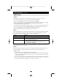
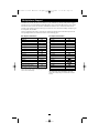
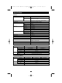
Cables and Interface Modules
The following cables are required for use with the B060-032 Modular Matrix KVM switch:
Function Cable
Console Interface Module to B060-032 KVM Cat5e Patch Cable (Tripp Lite
B060-032 KVM to Server Interface Module N001 series of patch cables)
Console Interface Modules For PS/2 Console B062-001-PS2
For USB Console B062-001-USB
Server Interface Modules For PS/2 Server B054-001-PS2
For SUN Server B054-001-SUN
For USB Server B054-001-USB
Daisy-chain Cables P770 Series of Cables
200701032 93-2287 B060-032 OM Update.qxd 1/15/2007 11:53 AM Page 3

4
Introduction
(continued)
POWER
STATION ID
RESET
123
4
5
6
7
8
9
10
11
12
13
14
15
16
17 18 19
20
21
22 23
24
25
26
27 28 29
30
31
32
2
3
5
1
4
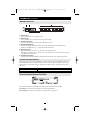
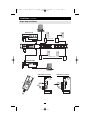
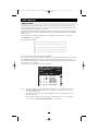
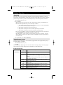
B060-032 Front View
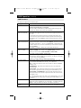
1. Firmware Upgrade Recovery Switch
During normal operation and while performing a firmware upgrade, this switch should be in the
NORMAL position. If a firmware upgrade operation does not complete successfully, slide this switch to
the RECOVER position and do a warm reset (see p. 31), to return the switch to its prior firmware state.
After returning the switch to its prior firmware state, slide the switch back to the NORMAL position to
attempt the firmware upgrade again, or to use the switch with its prior firmware.
2. Port LEDs
The Port LEDs are multicolored (Red / Green / Amber), and provide status information about their
corresponding CPU Ports as follows:
Color Condition Indication
Amber Steady Port is selected and the connected server is on.
Flashing Port is selected; Port is connected to a powered ON KVM switch
Red Steady Port is selected but connected server is OFF
Green Steady Port is not selected, the connected server is ON
Flashing Port is not selected: Port is connected to a powered ON KVM switch
Off Port is not selected and the server is OFF
3. Reset Switch
Pressing this switch in performs a System Reset.
Note: This switch is semi-recessed and must be pushed with a thin object - such as the end of a paper
clip, or a ballpoint pen.
4. Power LED
Lights to indicate that the B060-032 is powered up and ready to go.
5. Station ID LED
The B060-032’s Station ID is displayed here. If this is a Single Station installation (see p. 8), or the First
Station on a Daisy Chained installation (see p. 10), the B060-032 has a Station ID of 01.
On a Daisy Chained installation, the B060-032 auto-senses its position and displays the Station ID that
corresponds to its place in the chain. (see Port ID Numbering, p. 17 for details).
200701032 93-2287 B060-032 OM Update.qxd 1/15/2007 11:53 AM Page 4

5
Introduction
(continued)
6
4
2
1
5
3
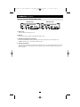
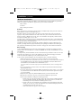
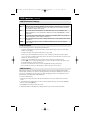
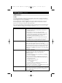
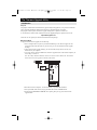
B060-032 Rear View
1. Power Socket
The power cord to the AC source plugs in here.
2. Power Switch
This is a standard rocker switch that powers the unit On and Off.
3. Console Port Section
The Cat5e cables from the Console Interface Modules plug in here.
4. Firmware Upgrade Port
The Firmware Upgrade Cable that transfers the firmware upgrade data from the administrator's
computer to the B060-032 (see p. 31), plugs into this RJ-45 connector.
5. Daisy Chain Ports
When Daisy Chaining Units (see p. 10), the daisy chain cables plug in here.
The upper port is the Chain In port; the lower one is the Chain Out port. The Chain In port is not used
on the Master (First Stage) unit.
6. Computer Port Section
The Cat5e cables that link the B060-032 to KVM cables that connect to the computers plug in here.
Console Interface Modules
The purpose of the Console Interface Modules is to provide flexibility for your installation by allowing
PS/2 and USB interfaces to be mixed and matched at the console side. With this approach, either type of
console can access and control any type of computer. The modules currently available are shown in the
table below:
Module Type
B062-001-PS2 For PS/2 consoles
B062-001-USB For all USB consoles (including Mac and Sun)
Console Interface Modules Front View
The front panel configuration of both B062 series modules is the same. It consists of two LEDs:
Link LED lights to indicate that the module is connected to the B060-032.
Power LED lights to indicate that the module is turned On and receiving power.
Link LED
Power LED
200701032 93-2287 B060-032 OM Update.qxd 1/15/2007 11:53 AM Page 5

6
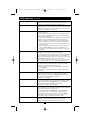
Console Interface Modules Rear View
1. Power Jack
The power adapter cable plugs in here.
2. I/O Jack
The cable that links the module to the B060-032 plugs in here.
3. Firmware Upgrade Recovery Switch
During normal operation and while performing a firmware upgrade, this switch should be in the
NORMAL position. See p. 4 for details about this switch.
4. Console Port Section
The cables from your keyboard, monitor and mouse plug in here. The keyboard and mouse ports of both
modules are labeled with an appropriate icon to indicate which is which. The B062-001-PS2 ports are
also color-coded.
1 2 3 4 1 2 3 4
B062-001-PS2
B062-001-USB
Introduction
(continued)
200701032 93-2287 B060-032 OM Update.qxd 1/15/2007 11:53 AM Page 6

7
Installation
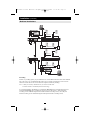
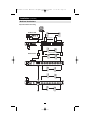
Overview
For convenience and flexibility that allows mixing the PS/2 and USB interfaces, the B060-032’s design
utilizes Console Interface Modules that act as signal translation intermediaries between the consoles and
the switch, and Server Interface Modules, that serve as intermediaries between the switch and the computers:
A separate Console Interface Module is required for each console you connect. Likewise, a separate Server
Interface Module is required for each computer connection. The Server Interface Module model number
for each interface is shown in the table below. The model numbers of the Console Interface Modules are
given in the table on p. 4.
Interface Server Interface Modules
PS/2 B054-001-PS2
SUN B054-001-SUN
USB B054-001-USB
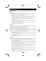
Before you Begin
1. Make sure that power to all the devices you will be connecting up have been turned off. You must
unplug the power cords of any computers that have the Keyboard Power On function.
2. To prevent damage to your installation, make sure that all devices on the installation are properly grounded.
B060-032
B061 Series Console
Interface Module
B054 Series Console
Interface Module
B054 Series Console
Interface Module
B054 Series Console
Interface Module
B054 Series Console
Interface Module
Multiple Modules
Multiple Modules
200701032 93-2287 B060-032 OM Update.qxd 1/15/2007 11:53 AM Page 7

8
Installation
(continued)
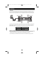
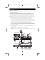
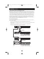
Single Stage Installation
In a Single Stage installation, there are no additional KVM switches daisy chained or cascaded down from
the first unit. To set up a single stage installation, refer to the diagram on p.9 (the numbers in the diagram
correspond with the numbers of the instruction steps), and do the following:
1. Connect the Console to the Console Interface Module
Plug your keyboard, mouse, and monitor into their respective ports on the Console Interface Module.
Each port is marked with an icon to indicate itself.
Note: The diagram shows the rear panel of both the B062-001-PS2 (PS/2 port) and B062-001-USB
(USB port) modules.
2. Connect the Console Interface Module to the B060-032
Use Cat5e cable to connect the Link port of the module to one of the Console ports on the B060-032's
rear panel. Up to four consoles can be connected per KVM.
Note: The distance between the Console Interface Module and the B060-032 must not exceed 500 feet.
(Repeat Steps 1 and 2 for any other consoles you wish to connect.)
3. Connect the B060-032 to the Server Interface Module
Use Cat5e cable to connect any available CPU Port to a Server Interface Module that is appropriate for
the computer you are installing.
Note: The distance between the B060-032 and the Server Interface Module must not exceed 500 feet.
4. Connect the Server Interface Module to the Computer
Plug the connectors on the Server Interface Module into the appropriate ports of the computer you are
installing.
Note: Repeat steps 3 and 4 for all the computers you wish to connect. Up to 32 computers can be con-
nected in this fashion.
5. After all computers have been cabled up, plug the female end of the power cord into the
B060-032’s Power Socket; plug the male end into an AC power source.
6. For each Console Module, plug its power adapter into an AC source; plug the power
adapter cable into the unit’s power jack.
7. Turn on the power to the B060-032.
8. Turn on the power to the computers.
200701032 93-2287 B060-032 OM Update.qxd 1/15/2007 11:53 AM Page 8

9
Installation
(continued)
6
2
1
4
3
5
Multiple Modules
Multiple Modules
B062-001-PS2
B062-001-USB
USB Cable Connection PS/2 Cable Connection
3
Single Stage Installation
200701032 93-2287 B060-032 OM Update.qxd 1/15/2007 11:53 AM Page 9

10
Installation
(continued)
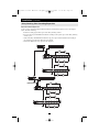
Multilevel Installations
The number of computers that can be added to your installation can be greatly expanded by performing a
multilevel installation. The B060-032 supports three types of multilevel installation:
• Daisy chained
• Cascaded
• Daisy chained plus cascaded
Overview
Daisy chaining refers to connecting two KVM switches via dedicated daisy chain ports. The switches are
strung together in a chain (see the diagram on p. 11).
With daisy chaining, none of the switch’s CPU ports are used to connect to the next switch. The port
capacity of a daisy-chained installation is the total of all the CPU ports of all the KVM switches on the
chain. For example, a B060-032 has 32 CPU ports. On an installation with eight daisy-chained switches
the number of available ports is 32 x 8 = 256.
Cascading involves using the CPU ports of a Parent KVM switch (one that is above a switch linked down
from it) to connect to a Child KVM switch. Cascading adds capacity to a KVM installation, but the parent
loses one CPU port for each cascaded KVM.
The B060-032 supports both daisy chaining and cascading. In addition, it supports combining the two
methods—providing enormous capacity and flexibility for expanding the installation. The following sec-
tions provide the information and procedures involved in setting up the various multilevel installations.
Daisy Chaining
Up to 7 additional B060-032 units can be daisy chained together; each capable of supporting four inde-
pendent consoles. The first B060-032 is considered the Master unit; the daisy chained B060-032s are con-
sidered Slaves.
In a complete daisy chained installation, the four consoles that belong to the Master switch can access and
control all of the computers (up to 256) on the installation. The four consoles belonging to each Slave
switch only control the computers (up to 32) connected to their switch.
To set up a daisy chained installation, refer to the diagram on page 11 and do the following:
1. Make sure that power to all the devices you will be connecting up has been turned off.
2. Use a daisy chain cable set (described in the Cables section, p. 3), to connect the Chain Out port of
the parent B060-032 unit to the Chain In port of the child B060-032 unit (First Station Out to
Second Station In, Second Station Out to Third Station In, etc.).
Note: You cannot use the Chain In port of the First Station B060-032, since it is the highest level
parent.
3. If you wish to install any consoles on this switch, follow the procedure described for the Single
Stage Installation on p. 8.
4. Use Cat5e cabling and a Server Interface Module (described in the Cables section, p. 4), to connect
any available CPU Port on the B060-032 to the Keyboard, Video and Mouse ports of the comput-
ers you are installing.
5. Repeat the above steps for any additional B060-032 units you wish to add to the chain.
6. Plug the power cord into an AC power source and into the B060-032's power socket.
7. Power up the installation according to the following procedure:
a. Switch on the power for the First Station. Wait for the unit to ascertain its Station ID and dis-
play it on the Station ID LED. (The Station ID for the First Stage unit is 01, the ID for the
Second Stage unit is 02, the ID for the Third Stage unit is 03, etc.).
b. Switch on the power for each Station on the installation in turn (Second Station, then Third
Station, etc.). In each case, wait for the Station ID to be ascertained and displayed on the cur-
rent Station before powering on the next one.
c. After all the Stations are up, power on the computers.
200701032 93-2287 B060-032 OM Update.qxd 1/15/2007 11:53 AM Page 10

11
Installation
(continued)
Multilevel Installations
1
Multiple Modules
Multiple Modules
Multiple Modules
Multiple Modules
B062-001-PS2
B062-001-USB
Cascading
Another way of adding capacity to your installation is to cascade additional KVM switches from the B060-
032’s CPU ports. Up to 32 additional KVM switches can be cascaded. Cascading does not increase the
number of consoles that can be used to control the computers (unlike daisychaining).
Note: 1. While you can daisy chain B060-032s, you cannot cascade them.
2. Switches cannot be cascaded beyond the second stage.
In a cascaded installation, the B060-032 is considered the First Stage unit; cascaded KVM switches are
considered Second Stage units. The B060-032 supports two types of cascade: 1) Protocol Interface
Cascading (see the installation diagram under Protocol Interface Cascading section), and 2) Physical
Interface Cascading (see the installation diagram under Physical Interface Cascading section).
200701032 93-2287 B060-032 OM Update.qxd 1/15/2007 11:53 AM Page 11

12
Installation
(continued)
Multilevel Installations
Protocol Interface Cascading
Protocol Interface Cascading refers to cascading to a second stage KVM switch (such as the eight port
Tripp Lite B007-008) that uses the same data transfer protocol as the first stage B060-032.
With this type of cascade, all of the separate switch OSDs are integrated so that when the B060-032
consoles bring up the OSD, it lists all of the computers connected to all of the units. In a full cascade,
256 computers can be controlled from a single B060-032 (8 B007-008 ports x 32 B060-032 ports = 256 total
ports).
To set up a Protocol Interface Cascade, refer to the installation diagram below and do the following:
1. Make sure that power to all the devices you will be connecting up has been turned off.
2. Use Cat5e cable to connect any available CPU Port on the First Stage unit (the B060-032) to a PS/2
style Server Interface Module (as described in the Cables section, p. 3); plug the adapter cable’s KVM
connectors to the Keyboard, Video, and Mouse Console ports of the Second Stage unit.
Note: The distance between the Second Stage unit and the B060-032 must not exceed 500ft.
3. Use KVM cable sets (as described in the Cables section of the Second Stage unit's User Manual), to
connect any available CPU port on the Second Stage unit to the Keyboard, Video, and Mouse ports of
the computer you are installing.
4. Plug the Second Stage unit's power adapter into an AC source; plug the power adapter cable into the
unit’s Power Socket.
5. Repeat steps 2 - 4 for any other Second Stage units you wish to connect.
6. Turn on the power for the First Stage unit; turn on the Second Stage unit, turn on the power to all the
computers.
1
Multiple Modules
Multiple Modules
B062-001-PS2
B054-001-PS2
B007-008
200701032 93-2287 B060-032 OM Update.qxd 1/15/2007 11:53 AM Page 12

13
Installation
(continued)
Multilevel Installations
Physical Interface Cascading
Physical Interface Cascading refers to cascading to a second stage KVM switch (such as the Tripp Lite
B022-016) that doesn’t utilize the same protocol as the first stage B060-032, but uses the same physical
interface (PS/2 or USB ports, for example).
The advantage of cascading to a switch like the B022-016 is that it yields enormous expansion capability.
Since it can be daisy chained to 31 additional B022-016s, up to 16,384 computers can be controlled from a
single B060-032 (32 B060-032 ports x 32 B022-016s x 16 ports per switch = 16,384 ports).
The operational difference between this method and Protocol Interface Cascading is that since the OSD
protocols are not the same, the OSDs of the cascaded B022-016s cannot be integrated. Unlike Protocol
Interface Cascading, the OSD that the operator works with is the OSD for each particular B022-016 - not
an OSD that incorporates all of the switches on the installation.
Therefore, in order to access a computer connected to a particular B022-016, the operator must first bring
up the B060-032’s OSD to access the target B022-016. The B022-016's OSD is then activated in order to
access the target computer.
In this type of installation, the B060-032 is considered the First Stage unit; the B022-016 is considered the
Second Stage unit. If there are additional B022-016s daisy chained down from the Second Stage B022-
016, the entire chain is seen as a Second Stage unit, with the top level B022-016 (the Master switch) as the
OSD access point for the entire chain.
To set up a Physical Interface Cascade, refer to the installation diagram below, and do the following:
1. Make sure that power to all the devices you will be connecting up has been turned off.
2. Use Cat5e cable to connect any available CPU Port on the First Stage unit (the B060-032) to a PS/2
style Server Interface Module (as described in the Cables section, p. 3); plug the Server Interface
Module's KVM connectors to the Keyboard, Video, and Mouse Console ports of the B022-016.
Note: The distance between the Second Stage unit and the B060-032 must not exceed 500ft.
3. Use KVM cable sets for the B022-016 to connect any available CPU port on the Second Stage unit to
the Keyboard, Video, and Mouse ports of the computers you are installing. Note that the B022-016
and the B060-032 use different types of cables.
4. Plug the power cord into the B022-016 switch's Power Socket and into an AC source (such as a surge
suppressor or UPS).
5. Repeat steps 2 - 4 for any other top level Second Stage units you wish to connect.
6. Turn on the power for the First Stage unit; turn on the power for all Second Stage units; turn on the
power to all the computers.
Note: If you are daisy chaining B022-016s, follow the instructions provided in the B022-016 User
Manual for chaining. Power on each chain according to the instructions in the manual.
200701032 93-2287 B060-032 OM Update.qxd 1/15/2007 11:53 AM Page 13

14
Installation
(continued)
Multilevel Installations
1
Multiple Modules
Multiple Modules
Physical Interface Cascading
B062-001-PS2
B054-001-PS2
B022-016
B022-016
200701032 93-2287 B060-032 OM Update.qxd 1/15/2007 11:53 AM Page 14

15
Installation
(continued)
Daisy Chaining Plus Cascading Expansion
B060-032 units can be daisy chained to other B060-032 units to produce extremely large KVM matrixes.
Under Protocol Interface Expansion, up to 8 daisy chained 32-port B060-032s can have an 8-port B007-008s
cascaded from each port, allowing up to 2,048 computers and 32 consoles in a full installation (8 x 32 x 8).
The four consoles belonging to the Master B060-032 can access and control all of the ports on all of the
switches on the entire installation. The four consoles belonging to each of the Slave units can access and
control all of their own ports and all of the ports on all of the switches that are cascaded down from them.
Under Physical Interface Expansion up to 8 daisy chained 32-port B060-032s can have can have 16-port
B022-016s cascaded from each port, and the B022-016s can be daisy chained to 32 levels, allowing up to
131,072 computers and 32 consoles in a full installation (8 x 32 x 32 x 16).
Protocol Interface Expansion
To set up a daisy chained/cascaded installation under Protocol Interface Expansion, refer to the diagram
below, and do the following:
1. Follow the cabling procedures given in the Cascading and Daisy Chaining sections.
2. Power up the daisy chained B060-032 Stations according to the sequence given in the Daisy Chaining
section (p. 10).
3. After all the daisy chained B060-032 Stations are up, power on the cascaded Stations.
4. After all the cascaded Stations are up, power on the computers.
B054-001-PS2
B054-001-PS2
B007-008
B060-032
B007-008
200701032 93-2287 B060-032 OM Update.qxd 1/15/2007 11:53 AM Page 15

16
Installation
(continued)
Daisy Chaining Plus Cascading Expansion
Physical Interface Expansion
To set up a daisy chained/cascaded installation under Physical Interface Expansion, refer to the diagram
below, and do the following:
1. Follow the cabling up procedures given in the Daisy Chaining sections.
2. Power up the daisy chained B060-032 Stations according to the sequence given in the Daisy Chaining
section (p. 10).
3. After all the daisy chained B060-032 Stations are up, power up each chain of B022-016s according to
the instructions provided in the B022-016 User Manual.
4. After all the B022-016s are up, power on the computers.
B054-001-PS2
B022-016
B022-016
B054-001-PS2
B022-016
B022-016
200701032 93-2287 B060-032 OM Update.qxd 1/15/2007 11:53 AM Page 16

17
Installation
(continued)
Topology Considerations
The use of RJ-45 CPU connectors, combined with our Auto Signal Compensation (ASC), allow signals to
travel up to 500 feet (150 meters) and still maintain reliability and high video resolution. This allows the
B060-032 installation to take advantage of the internal Cat5e and Cat6 wiring built in to most modern
commercial buildings.
Note: Although the B060-032 supports legacy CAT5 wiring, the performance and video quality may
degrade over longer distances.
Since the data signals are not transmitted in packets, the transmission cannot go through network hubs or
switches. Passive components such as patch panels, keystone jacks, patch cables, etc. can be used to chan-
nel the traffic.
Basic Operations
Hot Plugging
The B060-032 supports hot plugging—components can be removed and added back into the installation by
unplugging their cables from the ports without the need to shut the unit down. In order for hot plugging to
work properly, however, the procedures described below must be followed:
Switching Station Positions: On daisy chained installations, you can switch station positions by simply
unplugging from the old parent and plugging into a new one.
Hot Plugging Console Ports: Keyboard, monitor, and mouse can all be hot plugged. If you experience a
problem after you plug in a new mouse, do a system reset by pressing the reset switch on the B060-
032’s front panel (see p. 4 for details). If this doesn't resolve the problem, restart the computers that have
the problem.
Powering Off and Restarting
Powering off the B060-032 does not affect the computers attached to it. When you restart the B060-032,
you will regain control immediately. To replace a B060-032, simply power it down; unplug the cables;
plug them into the new unit; and power the new unit on.
Note: If any of the computers behave strangely after powering off and restarting, or changing a switch,
simply restart the computer.
Port Selection
Port Selection is accomplished either by entering Hotkey combinations from the keyboard, or by means of
the B060-032’s OSD (On Screen Display). OSD Operation is discussed in detail in the next chapter;
Hotkey Port Selection is discussed on p. 27.
Although hotkeys are handy for a single stage installation, we strongly recommend you use the more
powerful and versatile OSD - especially for daisy chained, cascaded, and combined installations.
Port ID Numbering
Each CPU port on a B060-032 installation is assigned a unique Port ID. You can access and control any
computer on the installation by specifying the Port ID of the port that it is connected to. Depending on
where the computer is on the installation, its Port ID will either have two or three parts.
Single Stage and Daisy Chained Installations
For single stage and daisy-chained installations, the Port ID is made up of two parts: a Station Number and
a Port Number:
• The Station Number - is a two digit number which reflects the switch’s position in the daisy chain
sequence. This corresponds to the number displayed on the front panel Station ID LED.
• The Port Number - reflects the port on the B060-032 Station that the computer is connected to.
• The Station Number precedes the Port Number.
Note: Station numbers from 1 - 9 are padded with a preceding zero, so they become 01 - 09.
For example, a computer attached to Port 12 of Station 6 would have a Port ID of: 06-12.
200701032 93-2287 B060-032 OM Update.qxd 1/15/2007 11:53 AM Page 17

18
Installation
(continued)
Basic Operations
Cascaded Protocol Interface Installations
The Port ID for computers on Protocol Interface cascaded installations is made up of three parts:
• The Station Number of the B060-032
• The Port Number on the B060-032 that the cascaded KVM switch links back to.
• The Port Number on the cascaded KVM switch that the computer is connected to.
For example, a computer attached to Port 8 of a KVM switch that is cascaded from Port 15 of a B060-032
in the Station 10 position, would have a Port ID of: 10-15-8.
Cascaded Physical Interface Installations
Under Physical Interface Expansion, B022-016s are cascaded down from the B060-032. Since the OSD
protocols are different, there are separate OSDs for each. When you invoke the OSD (see p. 19), the B060-
032 OSD screen comes up first. When you select the port that the target B022-016 is connected to, its OSD
screen replaces the B060-032’s, and you can select the computer you want to access from the B022-016
OSD screen. Aside from this difference, the port numbering follows the examples shown above.
User Management and Security
The B060-032 permits the creation of 6 operator profiles when the switch is either on a stand alone instal-
lation or is the Master switch of a multilevel installation, as follows:
• 1 Super Administrator
• 1 Administrator
• 4 Users
On a single stage installation, four operators have simultaneous and independent control of 32 computers. In a
daisy-chained installation, a maximum of 32 operators can exist (4 operators on the master KVM who can
access all systems, and 4 operators on each of the 7 Slave KVMs each having access to the 32 ports on that
KVM). Each Slave B060-032 also has 6 operator profiles, as above.
Note: 1. The Super Administrator can log in on a slave unit, but his authority only governs the
segment he logs in on - just like that of an ordinary Administrator.
2. Operator profiles are different from actual operators. The B060-032 has four console ports
and allows four actual operators to access the switch simultaneously. Operator profiles
specify the rights assigned to particular operators. Theoretically, one operator can use the
same operator profile to occupy all 4 console ports.
The Super Administrator has administrative power over the whole chain, he can assign and change pass-
words and access rights for all operators on all segments (see SET USERNAME AND PASSWORD, p. 23,
and SET ACCESSIBLE PORTS p. 24).
The Administrator’s power is limited to only that segment of the installation that the B060-032 he is logged in
on controls. He can assign and change passwords and access rights for all operators on his segment.
Both Super Administrator and Administrator have full User rights. The four Users have no administrative
rights. Depending on the permissions granted by the Super Administrator or Administrator, Users have
varying degrees of control over the computers on the installation: Full Access; View Only; No Access.
These rights are assigned on a port-by-port basis.
Operators (Super Administrator, Administrators, and Users) on the Master B060-032 can have User access
rights to all ports on the Slave KVMs. Access rights are given by the Super Administrator or Administrator
with the BUS AUTHORIZATION function (see p. 24).
The operators on Slave KVMs can only access computers on their segment. This includes any computers
connected to KVM switches that are cascaded down from the B060-032 they are logged in on.
200701032 93-2287 B060-032 OM Update.qxd 1/15/2007 11:53 AM Page 18

19
OSD Operation
OSD Overview
The B060-032 On Screen Display (OSD) provides a visual, menu-driven, mouse enabled, interface that
offers quick and convenient computer access and control, as well as efficient system administration includ-
ing user management (access rights, passwords, etc.).
Each OSD menu option activates a function that configures and controls the operation of the KVM instal-
lation. All procedures start from the OSD Main Screen. To bring up the OSD Main Screen, tap the Scroll
Lock key twice.
Note: [Scroll Lock] is the default OSD hotkey. You can optionally change the Hotkey to the Ctrl key
(see OSD Hotkey, p. 22, for details).
The login dialog box appears:
Key in a valid username and password, then press [Enter].
Note: If this is the first time that the OSD is being run, or if the password function has not been set, simply
press [Enter]. The OSD Main Screen comes up in Super Administrator Mode. In this mode, you have
access to all Administrator and User functions, and can set up operations (including password authorization
for the future), as you would like.
After you log in, a screen similar to the one below appears:
Note: 1. The diagram depicts the Super Administrator's Main Screen. The User Main Screen does not
show the F4 and F6 functions, since these are reserved for the Administrator and can’t be
accessed by ordinary Users.
2. The OSD always starts in List view, with the highlight bar at the same position it was in the
last time it was closed.
3. Only the ports that have been set accessible by the Administrator for the currently logged in
User are visible (see SET ACCESSIBLE PORTS, p. 24, for details).
ENTER NAME AND PASSWORD
USERNAME :
PASSWORD :
F1: GOTO
F2: LIST
F3: SET
F4: ADM
F5: SKP
F6: BRC
F7: SCAN X
F6: LOUT
SUPERADMINISTRATOR
SN:02/08
LIST:ALL
PN
01•
02•
03•
06•
05•
06•3
07•4
08•5
QV NAME
TRIPPLITE.1
TRIPPLITE.2
TRIPPLITE.3
FAXSERVER 1
FAXSERVER 1
WEBSERVER1
WEBSERVER2
MAILSERVER1
200701032 93-2287 B060-032 OM Update.qxd 1/15/2007 11:53 AM Page 19

20
OSD Operation
(continued)
OSD Main Screen Headings
Heading Explanation
SN This field shows the Station Number that the currently selected port is connected to.
The first number is the Station’s position in the chain; the second number shows the
total number of stations in the chain.
PN This column lists the Port Numbers for all the CPU ports on the installation. The
simplest method to access a particular computer is move the Highlight Bar to it, then
press Enter.
QV If a port has selected for Quick View scanning (see
Set Quick View Ports
, p. 24), an
arrowhead displays in this column to indicate so.
¤ The computers that are powered on and are On Line have a Sun symbol in this column
to indicate so.
NAME If a port has been given a name (see
Edit Port Names
, p. 23), its name appears
in this column.
OSD Navigation
Use the following procedures to navigate through OSD menus:
• To dismiss the Main Screen, and deactivate OSD, Click the X at the upper right corner of the OSD
Window; or press [Esc].
• To Logout, Click F8 at the top of the Main Screen, or press [F8].
• To move up or down through the list one line at a time, Click the Up and Down Triangle symbols
() or use the Up and Down Arrow Keys. If there are more list entries than there is room for on the
Main Screen, the screen will scroll.
• To move up or down through the list one screen at a time, Click the Up and Down Arrow
symbols (), or use the [Pg Up] and [Pg Dn] keys. If there are more list entries than there is room
for on the Main Screen, the screen will scroll.
• To activate a port, Double Click it, or move the Highlight Bar to it then press [Enter].
• After executing any action, you automatically go back to the menu one level above.
OSD Functions
OSD functions configure and control the OSD. Examples of what can be accomplished with the OSD
include: rapidly switching to any port; auto scanning specifically selected ports; limiting the list of ports you
wish to view; designating a port as a Quick View Port; managing port names; user management, system
administration, and making OSD setting adjustments.
To access an OSD function:
1. Either Click a Function Key field at the top of the Main Screen, or press a Function Key on the key-
board.
2. In the Submenus that appear make your choice either by Double Clicking it, or moving the Highlight
Bar to it, then pressing [Enter].
3. Press [Esc] to return to the previous menu level.
A complete description of the B060-032’s OSD operations are given in the sections that follow.
200701032 93-2287 B060-032 OM Update.qxd 1/15/2007 11:53 AM Page 20
Page is loading ...
Page is loading ...
Page is loading ...
Page is loading ...
Page is loading ...
Page is loading ...
Page is loading ...
Page is loading ...
Page is loading ...
Page is loading ...
Page is loading ...
Page is loading ...
Page is loading ...
Page is loading ...
Page is loading ...
Page is loading ...
-
 1
1
-
 2
2
-
 3
3
-
 4
4
-
 5
5
-
 6
6
-
 7
7
-
 8
8
-
 9
9
-
 10
10
-
 11
11
-
 12
12
-
 13
13
-
 14
14
-
 15
15
-
 16
16
-
 17
17
-
 18
18
-
 19
19
-
 20
20
-
 21
21
-
 22
22
-
 23
23
-
 24
24
-
 25
25
-
 26
26
-
 27
27
-
 28
28
-
 29
29
-
 30
30
-
 31
31
-
 32
32
-
 33
33
-
 34
34
-
 35
35
-
 36
36


Tripp Lite B060-032 Owner's manual
- Category
- KVM switches
- Type
- Owner's manual
- This manual is also suitable for
Ask a question and I''ll find the answer in the document
Finding information in a document is now easier with AI
Related papers
-
Tripp Lite B054-001-SUN User manual
-
Tripp Lite WEXT5-B060-032 User manual
-
-
-
-
-
-
Tripp Lite B004-HUA4-K Owner's manual
-
-
Other documents
-
MicroNet SP236 User manual
-
 Cables Direct KVM-201 Datasheet
-
 Shenzhen Kinan Technology KC2132i User manual
-
Digitus DS-23200 User manual
-
StarTech.com RKCONS1908GB User manual
-
 StarTech.com RACKCONS1908 Owner's manual
-
-
-
 StarTech.com SV1631DUTGB Datasheet
-
Approx APPKVMUSB2P Datasheet


