
© Copyright 2008 Printed 9/25/08
P.O. Box 5060
● Salina, Kansas 67402-5060
Manufacturing, Inc.
Operator’s Manual
!
Read the Operator’smanual entirely. When youseethissymbol,the subsequent instruc-
tions and warnings areserious - follow without exception. Your life and the lives of others
depend on it!
Table of Contents
14484
312-298M
RC15, RC25, and RC35 Series
Rotary Cutter
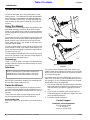
Cover illustration may show optional equipment not supplied with standard unit.
14490
Model RC15 Model RC25 Model RC35
14489

Table of Contents
Land Pride
Table of Contents
RC15, RC25, and RC35 Series Rotary Cutter 312-298M 9/25/08
© Copyright 2008 All rights Reserved
LandPrideprovidesthispublication“asis” without warrantyof anykind, eitherexpressedorimplied. While every precautionhasbeen takenin the preparationof this manual,
Land Pride assumes no responsibility for errors or omissions. Neither is any liability assumed for damages resulting from the useof the information contained herein. Land
Pride reserves the right to revise and improve its products as it sees fit. This publication describes the state of this product at the time of its publication, and may not reflect
the product in the future. The illustrations in this manual are not intended for safe and proper assembly or disassembly of equipment. The illustrations are intended for or-
dering parts only.
Land Pride is registered trademark.
All other brands and product names are trademarks or registered trademarks of their respective holders.
Printed in the United States of America.
Important Safety Information . . . . . . . . . . .1
Introduction . . . . . . . . . . . . . . . . . . . . . . . .8
Using This Manual . . . . . . . . . . . . . . . . . . . . . . . . . 8
Terminology: . . . . . . . . . . . . . . . . . . . . . . . . . . . 8
Definitions: . . . . . . . . . . . . . . . . . . . . . . . . . . . . 8
Owner Assistance . . . . . . . . . . . . . . . . . . . . . . . . . 8
Section 1 Assembly and Setup . . . . . . . . .9
Tractor Requirements . . . . . . . . . . . . . . . . . . . . . . 9
Hitch Assembly . . . . . . . . . . . . . . . . . . . . . . . . . . .9
RC15 Tailwheel . . . . . . . . . . . . . . . . . . . . . . . . . . 10
RC25 & RC35 Tailwheel . . . . . . . . . . . . . . . . . . . 10
Driveline Installation . . . . . . . . . . . . . . . . . . . . . . . 10
3-Point Tractor Hookup . . . . . . . . . . . . . . . . . . . . 10
Safety Guards . . . . . . . . . . . . . . . . . . . . . . . . . . . 11
Section 2 Operating Instructions . . . . . .12
Transporting . . . . . . . . . . . . . . . . . . . . . . . . . . . . 12
Operating Check List . . . . . . . . . . . . . . . . . . . . . . 12
Cutting Instructions . . . . . . . . . . . . . . . . . . . . . . . 12
Section 3 Adjustments . . . . . . . . . . . . . . .13
Cutting Height . . . . . . . . . . . . . . . . . . . . . . . . . . . 13
Section 4 Troubleshooting . . . . . . . . . . .15
Section 5 Maintenance and Lubrication .17
Maintenance . . . . . . . . . . . . . . . . . . . . . . . . . . . .17
Service Cutting Blades . . . . . . . . . . . . . . . . . . . . .17
Shearbolt Driveline . . . . . . . . . . . . . . . . . . . . . . . .17
Walterscheid Slip Clutch Run-In . . . . . . . . . . . . . .17
Eurocardan Clutch Run-In . . . . . . . . . . . . . . . . . .17
Eurocardan Clutch Assembly & Disassembly . . . .18
Storage . . . . . . . . . . . . . . . . . . . . . . . . . . . . . . . .18
4-Plate Slip Clutch . . . . . . . . . . . . . . . . . . . . . . . .19
Disassembly . . . . . . . . . . . . . . . . . . . . . . . . . .19
Assembly . . . . . . . . . . . . . . . . . . . . . . . . . . . . .19
2-Plate Slip Clutch . . . . . . . . . . . . . . . . . . . . . . . .20
Disassembly . . . . . . . . . . . . . . . . . . . . . . . . . .20
Assembly . . . . . . . . . . . . . . . . . . . . . . . . . . . . .20
Lubrication . . . . . . . . . . . . . . . . . . . . . . . . . . . . . .21
Tailwheel Spindle Hub . . . . . . . . . . . . . . . . . . .21
Tailwheel hub . . . . . . . . . . . . . . . . . . . . . . . . .21
Driveline U-Joints . . . . . . . . . . . . . . . . . . . . . .21
Gearbox . . . . . . . . . . . . . . . . . . . . . . . . . . . . .22
Driveline . . . . . . . . . . . . . . . . . . . . . . . . . . . . .22
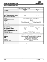
Section 6 Specifications and Capacities 23
Section 7 Appendix . . . . . . . . . . . . . . . . .26
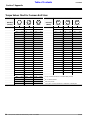
Torque Values Chart for Common Bolt Sizes . . . .26
Warranty . . . . . . . . . . . . . . . . . . . . . . . . . . . . . . .27

1
Important Safety Information
9/25/08
RC15, RC25, and RC35 Series Rotary Cutter 312-298M
Land Pride
Table of Contents
Important Safety Information
!
This Operator’s Manual is considered a part of the imple-
ment and should remain so when loaned or sold.
Prior To Operation
1. Do not allow anyone to operate this machine who has not
been properly trained in its safe operation.
2. Wear proper eye protection to prevent injury from
flying objects.
3. To prevent personal injury caused by thrown objects,
the use of front safety shields is strongly recommended.
4. Do not let children operate the implement.
5. Never allow passengers.
6. Do not leave the tractor or the implement unattended with
the engine running.
7. Before cutting, clear the area of objects and debris that
could become entangled in the blades or thrown from the
cutter.
During Operation
1. Never operate the cutter near people and do not stand near
the cutter while blades are in motion.
2. After striking an object, disengage PTO,shut offtractor and
inspect for damage before continuing.
3. Do not operate the cutter in reverse unless necessary. De-
bris may be thrown from thefront ofthe cutter; therefore, in-
creasing the risk of injury to the operator.
4. Checkthe cutter periodically for loose hardware and tighten
if necessary.
5. Never operate the cutter while in the raised transport posi-
tion.
6. Disengage the PTO when raised for transport or backing
up.
7. Travel slowly over rough terrain and be alert to holes and
gullies.
8. Use warning flags or approved warning lights at night and
during other periods of poor visibility. Do your best to pre-
vent highway accidents.
9. Be alert to traffic when crossing or cutting near roadways.
Always maintain complete control of the machine. Know
your state and local laws concerning highway safety and
regulations. Comply with these laws when transporting ma-
chinery.
10.Keep PTO shielding in place and in good condition. Do not
operate cutter with shields missing.
11.Always use proper PTO speed or machine damage may re-
sult. This cutter is designed to be used with a tractor using a
540 rpm rear PTO.
12.In order to maintain steering control, add ballast to tractor.
To determine the amount of ballast required refer to your
tractor operator’s manual.
During Maintenance
1. Before performing maintenance, disconnect PTO driveline
and securely block cutter on safe supporting stands. Do not
position stands under axle or wheel supports.
For your safety and to develop a better understanding of
your equipment, thoroughly read the Operator’s Sections
of this manual before operation.
Safety Notations
The SAFETY ALERT SYMBOL indicates that there is a
potential hazard to personal safety involved and extra
safetyprecautionsmustbe taken. When yousee this sym-
bol,bealert and carefullyreadthe message thatfollowsit.
In addition to design and configuration of equipment; haz-
ard control and accident prevention are dependent upon
the awareness, concern, prudence and proper training of
personnel involved in the operation, transport, mainte-
nance and storage of equipment.
Watch for the following Safety Notations throughout
your Operator’s Manual:
!
DANGER!
Indicates an imminently hazardous situation which, if not
avoided, will result in death or serious injury. This signal word
is limited to the most extreme situations.
!
WARNING!
Indicates a potentially hazardous situation which, if not avoid-
ed, could result in death or serious injury.
!
CAUTION!
Indicates a potentially hazardous situation which, if not avoid-
ed, may result in minor or moderate injury. It may also be used
to alert against unsafe practices
Safety Rules
Most accidents are the result of negligence and careless-
ness,causedbyfailureofthe operator to followsafety pre-
cautions. Even though your implement is designed with
manybuilt-insafetyfeatures,thefollowingprecautions are
mandatory to prevent such accidents.
Make sure everyone that uses this machine has read the
Operator’s Manual and understands how to operate it
safely.
!
These rules and instructions
must be reviewed at least annually
by all operators!

2
Important Safety Information
RC15, RC25, and RC35 Series Rotary Cutter 312-298M 9/25/08
Land Pride
Table of Contents
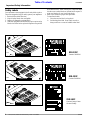
Safety Labels
Your implement comes equipped with all safety labels in place.
They were designed to help you safely operate your implement.
1. Read and follow label directions.
2. Keep all safety labels clean and legible.
3. Replace all damaged or missing labels.
4. Some new equipment installed during repair require safety
labels to be affixed to the replaced component as specified
by the manufacturer. When ordering new components make
sure the correct safety labels are included in the request. To
order new labels go to your Land Pride dealer.
5. Refer to this section for proper label placement.
To install new labels:
a. Clean the area the label is to be placed.
b. Peel backing from label. Press firmly on surface
being careful not to cause air bubbles under label.
818-130C
Caution 540 RPM
14217
14217
818-161C
Caution Rotary Cutter
General Safety
818-130C
Caution 540 RPM
14493
Model RC15 & RC25
Model RC35
Model RC15 & RC25


8
Introduction
RC15, RC25, and RC35 Series Rotary Cutter 312-298M 9/25/08
Land Pride
Table of Contents
Introduction
For prompt service always use the serial number and
model number when ordering parts from your Land Pride
dealer. Be sure to include your serial and model numbers
in correspondence also.
Your dealer wants you to be satisfied with your new ma-
chine. If for any reason you do not understand any part of
this manual or are not satisfied with the service received,
the following actions are suggested:
1. Discuss the matter with your dealership Service Man-
ager make sure he is aware of any problems you may
have and that he has had the opportunity to assist
you.
2. If you are still not satisfied, seek out the Owner or
General Manager of the dealership, explain the prob-
lem and request assistance.
3. For further assistance write to:
Product Support
Land Pride, Service Department
1525 East North Street
P.O. Box 5060
Salina, Ks. 67402-5060
Serial Number Plate Location
Figure 1
15025
14495
Model RC15 & RC25
Model RC35
Land Pride welcomes you to the growing family of new
product owners. This implement has been designed with
care and built by skilled workers using quality materials.
Proper assembly, maintenance, and safe operating prac-
tices will help you get years of satisfactory use from the
machine.
Using This Manual
ThisOperator’sSectionisdesigned tohelpfamiliarizeyou
with safety, assembly, operation, adjustments, trouble-
shooting, and maintenance. Read this manual and follow
therecommendationstohelpensuresafeandefficient op-
eration.
The warranty sheet should be filled out by the owner and
dealer at the time of purchase. After completion give the
dealer the white copy and send the pink copy to Great
Plains. Keep your copy in the manual for use when corre-
sponding with the dealer.
To order a new Operator or Parts Manual contact your au-
thorized dealer or write to the address listed below in the
Owner Assistance paragraph. Include the model and seri-
al numbers of your unit.
The information contained within this manual was current
at the time of printing. Some parts may change slightly to
assure you of the best performance.
Terminology:
"Right " or "Left" as used in this manual is determined by
facing the direction the machine will travel while in use un-
less otherwise stated.
Definitions:
IMPORTANT: Information, related to it’sproceeding topic,
that the author feels would be of use.
Owner Assistance
If customer service or repair parts are required contact
yourlocal LandPridedealer.Hehastrainedpersonnel, re-
pair parts, and the equipment needed to service your im-
plement.
These parts have been specially designed and should
only be replaced with genuine Land Pride parts.
Serial Number Plate
Refer to the Figure 1 for the location of your serialnumber
plate.
NOTE: A special point of information related to it’s
preceding topic. The author’s intention is that you
read and note this information before continuing.

9
Section 1 Assembly and Setup
9/25/08
RC15, RC25, and RC35 Series Rotary Cutter 312-298M
Land Pride
Table of Contents
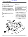
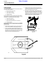
Hitch Assembly Diagram
Figure 1-1
14244
Section 1 Assembly and Setup
Tractor Requirements
The RC15, RC25 and RC35 Rotary Cutters are designed
for use with tractors that are equipped with a Type 1 (540
RPM; 1 3/8" - 6 spline) rear power take-off (PTO) per
ASAE (American Society of Agricultural Engineers)
S203.12 APR93.
Thetractormustalsoprovidefor3-pointhitchattachments
that fall within the scope set forth by ASAE S217.11.
RC15: Category l withtractors' rated PTO horsepower no
lessthan15normorethan50;RC25:CategoryIstandard
or II with tractors' rated PTO horsepower no less than 20
nor more than 75; RC35: Category II with tractors' rated
PTO horsepower no less than 30 nor more than 120
!
CAUTION!
Do notoverspeed PTO ormachine damage may result.This cut-
ter is designed to be used with a tractor using a 540 RPM rear
PTO.
NOTE: In order to maintain steering control, ballast
may need to be added to your tractor. To determine
whetherornottoaddtheballast,refertoyourtractor’s
operator manual.
Hitch Assembly
Refer to Figure 1-1:
1. Assemble hitch straps (#1) to inside of lower hitch an-
gles welded to cutter deck with hitch pin (#2), lock
washers (#3), and nuts (#4).
2. Attach hitch braces (#5) to inside of lugs welded to
deck using 3/4” bolt (#6), lock washer (#7), and nut
(#8).
3. Installpivotingupperhitch(#9)toinsideofhitchstraps
(#1) with hitch braces (#5) on the outside. Install 1”
bolt (#10) and nut (#11). Do not overtighten as upper
must be allowed to pivot.
4. Tighten all hardware to torque listed in the Torque Val-
ues Chart in the “Appendix” section on page 26.
NOTE: There are two mounting holes in each lower
hitch angle. The top hole is for standard category
hitch tractors; the lower hole is for smaller horsepow-
er rated tractors without adequate ground clearance
when cutter is raised for transport.
NOTE: Do not tighten hardware until assembly is
complete.

10
Section 1 Assembly and Setup
RC15, RC25, and RC35 Series Rotary Cutter 312-298M 9/25/08
Land Pride
Table of Contents
14249
Tractor 3-Point Hitch
Figure 1-4
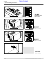
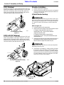
RC15 Tailwheel
As shown in Figure 1-3, attach tailwheel boom (#1) in tail-
wheel risers welded to cutter deck using 1/2” x 3 1/4” long
bolts (#2), lock washers (#3), and nuts (#4). Attach tail-
wheel yoke spindle (#5) to boom weldment (#1) and se-
cure with washers (#6) and cotter pin (#7).
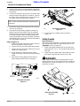
RC25 & RC35 Tailwheel
As shown in Figure 1-3, attach tailwheel boom (#1) in tail-
wheel risers welded to cutter deck using 3/4” -10 x 4 1//2”
long bolts (#2), lock washers (#3), and nuts (#4). Attach
tailwheelyokespindle (#5) to boom weldment(#1)andse-
cure with washers (#6 & #8) and roll pin (#7).
RC15 Tailwheel Assembly
Figure 1-3
14221
RC25 & RC35 Tailwheel Assembly
Figure 1-3
14245
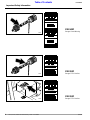
Driveline Installation
1. Grease input shaft on gearbox.
2. Slide the drivelineendwith the slip clutch or shearbolt
oversplined shaft ofthegearboxand securewithlock-
ing device on driveline.
3-Point Tractor Hookup
!
DANGER!
Tractor hook-up can be hazardousto your health or that of your
helper. Do not allow anyone to stand between the cutter and the
tractor during hook-up operations. Do not operate the hydrau-
lic 3-point lift controls while someone is directly behind the
tractor.
Refer to Figure 1-5:
1. Locate the cutter ona flat,levelsurface.
2. Determine the hitchcategory of the tractorthat will be used:
A Category I tractor willhavea lower hitchlink
hole diameter of7/8". The top link holediameter
(implement end) willbe3/4".
A Category II tractor willhavea lower hitchlink
hole diameter of1 1/8". The top linkhole diameter(imple-
ment end) willbe 1".
3. Slowlybackthetractoruptothecutterandusethetractors3-
point hydrauliccontrol to adjust the lowerlinkarms up or
downto matchthe heightof the cutter hitch pins.
!
DANGER!
Engage parking brake, shut off tractor and remove key before
dismounting from the tractor.
4. If the tractor is a Category I, simply position the lower
link arms to "insert" the hitch pin into the lower hitch
linkhole.IfthetractorisCategoryII,installtheadaptor
bushingonthehitchpin beforeinsertioninto thelower
link hole. (Adapter bushing not required on RC2584
and all RC35 series rotary cutters.)

11
Section 1 Assembly and Setup
9/25/08
RC15, RC25, and RC35 Series Rotary Cutter 312-298M
Land Pride
Table of Contents
5. Install a 7/16" lynch pin or other fastener (supplied by
customer)thruthehitchpinhole tolockthelowerlinks
into position.
6. Connectthedrivelinetothetractor’s PTOoutputshaft
and secure with locking device on driveline. Connect
the safety chain to the hitch brace on the cutter to re-
strict outer shield of driveline from rotating.
7. Connect the top link to the upper pivot hitch using the
3/4" hitch pin supplied.
8. Start the tractor and slowly engage the tractors hy-
draulic 3-point to lift the cutter. Check for sufficient
drawbar clearance. Move the drawbar ahead, aside,
or remove if required. Watch the telescoping move-
ment of the driveline to ensure that it does not bottom
outwhileliftingthe3-point.Ifthedrivelinedoesbottom
out, it will require shortening:
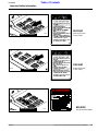
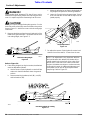
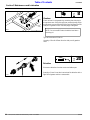
Refer to Figure 1-5:
a. Holdthehalf shaftsnexttoeachotherintheshort-
est working position and mark them.
b. Shorten the inner and outer guard tubes equally.
c. Shorten the inner and outer profiles by the same
length as the guard tubes.
d. Proper overlap is a minimum of one-half the
lengthofeachtube,withbothtubesbeingofequal
length.
e. Round off all sharp edges and remove burrs.
grease sliding profiles before re-assembly.
NOTE: Chain should be attached at implement end
of driveline.
Cutting the PTO Shafts
Figure 1-5
13588
9. If check chain kit is added. install as shown in
Figure 1-6.
Safety Guards
Refer to Figure 1-7:
After Rotary Cutter assembly is complete, tighten all hard-
ware to the torque listed on Torque Values Chart in the
“Appendix” section on page 26.
1. Install chain guard assembly (#1) to the cutter front
angle using 1/2” -13 x 1 1/2” long bolts (#2) and whiz
nuts (#3).
2. Install side chain guards (#4) to the bottom of cutter
front angle using bolts (#2) and whiz nuts (#3).
!
DANGER!
Rotary cutters have the ability to discharge objects at high
speeds; therefore, the use of front safety shields is strongly rec-
ommended when cutting along highways or in an area where
people may be present.
Check Chain Installation
Figure 1-6
14247
Safety Guard Assembly
Figure 1-7
14246

12
Section 2 Operating Instructions
RC15, RC25, and RC35 Series Rotary Cutter 312-298M 9/25/08
Land Pride
Table of Contents
Section 2 Operating Instructions
Transporting
!
CAUTION!
When traveling on public roads at night or during the day, use
accessory lights and devices for adequate warning to opera-
tor’s of other vehicles. Comply with all federal, state and local
laws.
1. When raising the cutter to the transport position be
sure that driveline does not contact tractor or cutter.
2. Be sure to reduce tractor ground speed when turning;
and, leave enough clearance so the cutter does not
contact obstacles such as buildings, trees or fences.
3. Select a safe ground speed when transporting from
one area to another. When traveling on roadways,
transport in such a way that faster moving vehicles
may pass you safely.
4. When traveling over rough or hilly terrain, shift tractor
to a lower gear.
Operating Check List
In addition to design and configuration of equipment; haz-
ard control and accident prevention are dependent upon
the awareness, concern, prudence and proper training in-
volved in their operation, transport, maintenance and stor-
age of equipment. Before beginning to cut the following
inspection should be performed.
NOTE: Always disengage the tractor’s PTO before
raising the cutter to transport position.
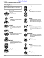
Operating Checklist
Check Reference
“Safety Rules” in this Manual. page 1
Check oil level in gearboxes. Refer to
"Maintenance & Lubrication".
Section 5
page 22
Check that all plugs in gearbox have
been replaced properly.
Section 5
page 22
Be sure nuts and bolts are tight. Section 1
Be certain all guards and shields are in
place.
Section 1
Lubricate the cutter as needed. Refer to
"Maintenance & Lubrication".
Section 5
page 17
!
CAUTION!
To prevent personal injury caused by thrown objects, the use of
front & rear safety guards is strongly recommended! To avoid
injury or death from entanglement in rotating drivelines, the
drive gearbox shields must be in place and secure when operat-
ing.
!
DANGER!
Rotary cutters have the ability to discharge objects at high
speeds; therefore, the use of front safety shields is strongly rec-
ommended when cutting along highways or in an area where
people may be present.
Cutting Instructions
1. Your cutter is equipped with free swinging cutting
blades to reduce shock loads to the cutter if striking
obstacles.
2. Startthemachineslowly;donotuse fullthrottle.Allow
10 seconds for cutter blades to become aligned prop-
erly before going to full power.
3. Thegroundspeed depends on twothings;thedensity
of the material to be cut, and the size of the tractor.
Never run fast enough to overload the tractor.
4. It is important to maintain 540 RPM PTO speed. Loss
of PTO speed will allow the blades to hinge back and
result in ragged, uneven cutting.
5. This cutter was designed to cut grass and light brush
in right-of-ways, pastures and for shredding row crop
residues.
!
CAUTION!
Damage may occur if exceeding the cutting capacity of the cut-
ter!
!
CAUTION!
Do not over speed PTO or machine damage may result. This
cutter is designed to be used only with a tractor having a 540
RPM rear PTO.

13
Section 3 Adjustments
9/25/08
RC15, RC25, and RC35 Series Rotary Cutter 312-298M
Land Pride
Table of Contents
Section 3 Adjustments
Cutting Height
There are 4 primary adjustments that should be made pri-
or to actual field operations:
a. Deck level from left to right
b. Tractor top link length
c. Tractor lower link height
d. Tailwheel height
Proper adjustment of each of these items will provide for
higher efficiency, improved cutting performance and long-
er blade life. The following tools will be needed:
a. Pliable tape measure
b. Spirit or carpenters level
c. Open end or hex end wrench or socket set
d. Protective gloves
Havingcompleted 3-Point Tractor Hookup in the “Assem-
blyand Setup” section on page 10 locate the tractor on a
flat level surface.
1. Use the tractor’s hydraulic 3-point control to lower the
cutter until the tailwheel contacts ground surface.
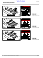
2. Place a spirit level or other suitable leveling device on
the front of the cutter deck as shown in Figure 3-1. Ad-
just either one or both of the tractors lower link height
adjustments to level the deck from left to right. Some
tractors have only a single adjusting crank.
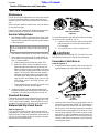
Deck Leveling
Figure 3-1
14240
3. Similarly, place a level on either of the main deck
channels.Use the tractors 3-point hydrauliccontrol to
level the cutter deck from front to rear.
4. With cutter in cutting position, adjust tractor lop link
until upper hitch pin is aligned vertically with lower
hitch pins, see Figure 3-2. Position "A" is for standard
category hitch tractors and position "B" is for smaller
horsepower rated tractors without adequate ground
clearance when cutter is raised for transport.
Top Link Adjustment
Figure 3-2
10419

14
Section 3 Adjustments
RC15, RC25, and RC35 Series Rotary Cutter 312-298M 9/25/08
Land Pride
Table of Contents
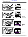
Best Deck Attitude for Cutting
Figure 3-5
14254
!
DANGER!
Engage parking brake, disengage PTO, shut off tractor and re-
move key before proceeding. Ensure that all moving parts have
come to a complete stop before dismounting from the tractor.
!
CAUTION!
Wear apair of gloveswhen performing thisoperation. Go tothe
backof thecutter and carefullyrotateeach blade to theposition
shown in Figure 3-1. Avoid direct contact with the cutting edge
of the blade.
5. Measure the distance from the end (cutting tip) of the
blade to the ground surface. This distance is the nom-
inal cutting height, see Figure 3-3.
Refer to Figure 3-4:
6. Ifthecuttingheightistoo high or too low, the tailwheel
must be adjusted as follows:
a. Usethetractors3-point hydrauliccontrol to lift the
cutter such that the tailwheel clears the ground
surface.
b. Remove attaching hardware; bolt (#1), nut (#2),
and lock washer (#3).
Nominal Cutting Height
Figure 3-3
14253
c. Adjust the tailwheel up or down to the desired cut-
ting height and replace the attaching hardware.
d. Lower the 3-point hitch and repeat steps 3 and 4
to be sure the deck is level and the top link is ad-
justed properly.
7. Re-adjust the tractors 3-point hydraulic control such
that the front of the cutter is 1" lower than the rear.
Height Adjustment
Figure 3-4
14223
NOTE: This adjustment is very important. With the
deck positioned at this attitude, the blades will be
cutting material only at the front of the cutter. If the
deck is level, or the rear of the cutter is lower than
the front, the blades are subject to continuous mate-
rial flow which results in additional blade wear and
horsepower loss as well as more frequent blade
sharpening. Refer to Figure 3-5.

15
Section 4 Troubleshooting
9/25/08
RC15, RC25, and RC35 Series Rotary Cutter 312-298M
Land Pride
Table of Contents
Section 4 Troubleshooting
Problem Cause Solution
Oil seal leaking
Gearbox overfilled Drain to side plug hole.
Seals damaged Replace seals
Grass or wire wrapped on
shaft in seal area
check seal areas daily
Driveline yoke or cross failing
Shock load Avoid hitting solid objects
Needs lubrication Lubricate every 8 hours.
Driveline clutch slipping or
Shear bolt breaking
Scalping the ground Raise cutting height
Cutting too fast Reduce travel speed
PTO being engaged too
fast at high engine rpm
Slowly engage PTO at low engine rpm
Cutting over solid objects Avoid solid objects
Bent Driveline (NOTE: driveline should
be repaired or replaced if bent)
Contacting frame Reduce lift height in transport position
Contacting drawbar Reposition drawbar
Bottoming out Shorten driveline
Driveline
telescoping tube failing
Shock load Avoid hitting solid objects
Driveline
telescoping tube wearing
Needs lubrication Lubricate every 50 hours
Blades wearing excessively
Cutting on
sandy ground
Raise cutting height
Contacting
ground frequently
Raise cutting height
Blades Breaking
Hitting solid objects Avoid solid objects
Blades hitting each other Blade carrier needs to be timed
Blades coming loose
Blades not
tightened properly
Tighten blade hardware (refer to
"Servicing Cutter Blades" on page 16.
Blade carrier becomes loose
Running loose in the past Replace gearbox output shaft and blade carrier
Blade carrier hardware not
tight enough
Tighten to specified torque
Blade bolt holes worn
Blade hardware running loose Replace blades and blade bolts if worn
Blade carrier bent
Hitting solid objects Avoid hitting solid objects and replace blade carrier
Excessive side skid wear
Cutting height not level Adjust cutter height
Soil abrasive Adjust cutter height
Cutting too low Adjust cutter height
Tail wheel support failing
Lowering too fast Adjust rate of drop
Hitting objects when turning Reduce speed on turns

16
Section 4 Troubleshooting
RC15, RC25, and RC35 Series Rotary Cutter 312-298M 9/25/08
Land Pride
Table of Contents
Excessive vibration
Blades locked together Unlock blades
Driveline bent Replace driveline
Blades loose Tighten blade bolts
Blade carrier bent Replace blade carrier
Blade broken Replace blade
Blade will not swing Remove and inspect blade
Blades have unequal weight Replace both blades
Problem Cause Solution

17
Section 5 Maintenance and Lubrication
9/25/08
RC15, RC25, and RC35 Series Rotary Cutter 312-298M
Land Pride
Table of Contents
Section 5 Maintenance and Lubrication
Maintenance
Proper servicing and adjustment is the key to the long life
of any farm implement. With careful and systematic in-
spection, you can avoid costly maintenance, time and re-
pair.
After using your cutter for several hours, check all bolts to
be sure they are tight.
Replace any worn, damaged or illegible safety decals by
obtaining new decals from your Land Pride Dealer.
Service Cutting Blades
1. Both blades should be sharpened at the same angle
as the original cutting edge and must be replaced or
regroundatthe same time to maintainproperbalance
in the cutting unit.
2. Both blades should weigh the same after sharpening.
3. When replacing or sharpening the cutter blades, ex-
amine bolts for excessive wear and replace if neces-
sary. To replace blades:
a. Order blade bolt Land Pride part # 802-277C.
b. Blade shim (#30), must be installed to insure a
tight and proper fit between the blade bolt and
blade.Too tight a fit maycause bladetonot swing
back into proper cutting position after striking ob-
stacles. Too loose a fit will cause play between
blade bolt and blade resulting in excessive wear
on blade carrier, blade bolts and blades. Three
sizes of shims are available: 16 ga., part no. 312-
075D; 18 ga., part no. 312-082D; & 20 ga., part
no. 312-089D.
c. Torque bladebolt locknutto450 ft.pounds.Usea
3’ long pipe to achieve proper torque.
4. If replacing dishpan, nut on gearbox output shaft
should be torqued to 450 foot/pounds and cotter pin
installed in nut with legs securely bent around nut.
Shearbolt Driveline
Cutter drive components are protected from shock loads
by a 1/2" shear bolt. If shear bolt fails, replace with a 1/2"
x 3 1/2" long hex bolt, grade 2. Shear bolt failure can be
avoided by engaging the PTO slowly at low engine rpm.
Walterscheid Slip Clutch Run-In
Refer to Figure 5-1:
RC15 and RC25 Rotary Cutters drive components are
protected from shock loads by a two plate slip clutch and
the RC35 Rotary Cutters are protected by a fourplate slip
clutch. The clutch should slip during operation to protect
the cutter from excessive loads.
Prior to initial operation and after long periodsofinactivity,
the Friction Clutch should be "run-in".
a. Tighten all 4 nuts uniformly until the spring load is
low enough that the clutch slips freely with the
PTO engaged.
b. Turn nuts fully back. Clutch is ready for use.
!
CAUTION!
Engage parking brake, disengage PTO, shut off tractor, and re-
move key before making any of the following adjustments.
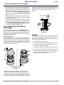
Eurocardan Clutch Run-In
Refer to Figure 5-2:
1. Using a pencil or other marker, scribe a line across the
exposed edges of the clutch plates and friction disks.
2. Carefully loosen each of the 8 spring retainer nuts on
theclutchhousingatotalofEXACTLY 2 revolutions.It
will be necessary to hold the hex end of the retainer
bolt in order to count the exact number of revolutions.
3. Startthetractor andengagethePTOdrivefor2-3sec-
onds to permit slippage of the clutch surfaces. Disen-
gage the PTO, then re-engage a second time for 2-3
seconds. Disengage the PTO, shut off tractor and re-
move key. Wait for all components to stop before dis-
mounting from tractor.
NOTE: Care should be taken in order not to remove
any more material than necessary when sharpening
blades.
Slip Clutch Driveline
Figure 5-1
14221
Clutch
Figure 5-2
13693

18
Section 5 Maintenance and Lubrication
RC15, RC25, and RC35 Series Rotary Cutter 312-298M 9/25/08
Land Pride
Table of Contents
4. Inspect the clutch and ensure that the scribed mark-
ingsmadeontheclutchplateshavechangedposition.
If any two marks on a friction disk and plate are still
aligned,such indicatesthatslippage hasnotoccurred
and the clutch must be disassembled to separate the
friction disks, see "Clutch Assembly and Disassem-
bly", on page 18.
5. Tighteneachofthe8springretainernutsontheclutch
housingEXACTLY2 revolutionsto restoretheoriginal
clutch setting pressure.
6. The clutch should be checked during the first hour of
cutting and periodically each week. An additional set
of scribe marks can be added to check for slippage.
See "Clutch Assembly and Disassembly", on page
18, to adjust for proper spring length.
Eurocardan Clutch Assembly &
Disassembly
If the clutch run-in procedure, see "Clutch Run-In"on
page 17, indicated that one or more of the friction disks did
not slip, the clutch must be disassembled to separate the
friction discs. Referto the PartsSectionof this manualfora
detailed parts breakdown.
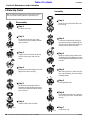
Refer to Figure 5-3:
Disassemblyof the clutch is simply a matter of first remov-
ing the spring retainer nuts (#1), springs (#2) and bolts
(#3) from the assembly. Each friction disc (#4) must then
beseparatedfromthemetalsurfaceadjacent toit.Inspect
all parts for excessive wear and condition. Clean all parts
that do not require replacement.
The original friction disc thickness is 1/8" (3.2mm) and
should be replaced if the thickness falls below 3/64"
(1.1mm). If the clutches have been slipped to the point of
"smoking", the friction discs may bedamaged and should
be replaced. Heat build-up may also affecttheyokejoints.
Clutch Disassembly
Figure 5-3
14714
Install newfriction discs if needed and reassemble all com-
ponents in proper order. Progressively tighten each spring
retainer bolt until the spring length is 1.010 inches,
Figure 5-4.
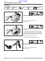
Storage
Attheendoftheworkingseasonorwhenthecutterwillnot
be used for a long period, it is good practice to clean off
any dirt or grease that may have accumulated on the cut-
ter and any of the moving parts.
1. Clean the cutter as necessary.
2. Check the blades for wear and replace if necessary.
3. Inspect the cutter for loose, damaged or worn parts
and adjust or replace as needed.
4. Lubricate as noted in Lubrication, startingonpage 21.
5. Store the cutter inside if possible for longer cutter life.
6. Repaint parts where paint is worn or scratched to pre-
vent rust. Ask your dealer for Aerosol Land Pride
Beige touch-up paint #821-011C.
Clutch Adjustment
Figure 5-4
13741
Page is loading ...
Page is loading ...
Page is loading ...
Page is loading ...
Page is loading ...
Page is loading ...
Page is loading ...
Page is loading ...
Page is loading ...
Page is loading ...
-
 1
1
-
 2
2
-
 3
3
-
 4
4
-
 5
5
-
 6
6
-
 7
7
-
 8
8
-
 9
9
-
 10
10
-
 11
11
-
 12
12
-
 13
13
-
 14
14
-
 15
15
-
 16
16
-
 17
17
-
 18
18
-
 19
19
-
 20
20
-
 21
21
-
 22
22
-
 23
23
-
 24
24
-
 25
25
-
 26
26
-
 27
27
-
 28
28
-
 29
29
-
 30
30


Ask a question and I''ll find the answer in the document
Finding information in a document is now easier with AI
Related papers
-
 Land Pride RCSM3596 User manual
-
 Land Pride RCR2584 User manual
-
 Land Pride Brush Cutter Parallel Arm Rotary Cutter User manual
-
 Land Pride RC35120 RCM35120 User manual
-
Land Pride RCR15 User manual
-
 Land Pride RCF45180 User manual
-
 Land Pride at 2560 User manual
-
 Land Pride FD2560 User manual
-
 Land Pride RCR1860 Series User manual
-
 Land Pride RCR18 User manual


Other documents
-
Bad Boy 5´ Cutter Owner's Operation Manual
-
Kodiak PT-40 Owner's manual
-
Metabo B 561 Operating instructions
-
Bercomac BRCMD60SC 700788 User manual
-
-
Craftex CX Series CX804 Owner's manual
-
Buhler FK372 User manual
-
Klutch Electric Rod and Rebar Cutter Owner's manual
-
 John Deere HX10 User manual
-
Buderus RC35 Installation And Servicing Instructions
