- 2 -
7301450-100 Rev. A
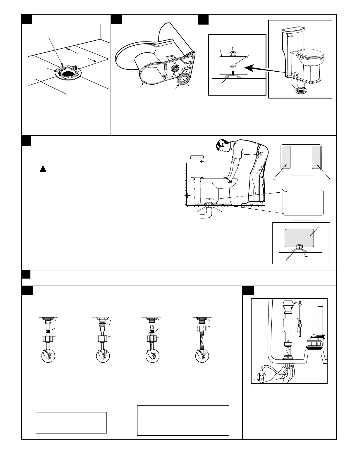
8a
8b
Before continuing, determine the type of water supply connection you have from the chart
below and use the appropriate assembly parts required to properly reconnect the water supply.
DO NOT use plumber's putty to seal these fittings.
CAUTION: DO NOT USE
CONE WASHER WITH
PLASTIC SUPPLY LINE.
These parts must be used as
illustrated to insure water-tight
connection. Use of existing
coupling nut may result in
water leakage. Water supply
tube or pipe must extend at
least 1/2" inside threaded
shank of valve (does not
apply to flanged tubing).
Use existing
coupling nut
and washer.
Use existing spiral cone
washer. Fluidmaster
cone washer may not
seal completely on
spiral type supply line.
Captive cone washers
already included. No
additional washers needed.
CAUTION: Overtightening of
LOCK NUT or COUPLING NUT
could result in breakage and
potential flooding.
METAL/COPPER
FLARED TUBING
METAL FLANGED
TUBING
METAL SPIRAL
TUBING
VINYL/BRAIDED
CONNECTOR
LOCK NUTLOCK NUT LOCK NUT LOCK NUT
COUPLING
NUT
COUPLING
NUT
EXISTING
COUPLING
NUT
COUPLING
NUT
WATER
SHUT-OFF
WATER
SHUT-OFF
WATER
SHUT-OFF
WATER
SHUT-OFF
CONE
WASHER
EXISTING
CONE
WASHER
EXISTING
WASHER
With correct washers in place (see
Step 8a), tighten COUPLING NUT
1/4 turn beyond hand tight.
DO NOT OVERTIGHTEN.
6
7
INSTALL TOILET SEAT Install toilet seat in accordance with manufacturer's directions.
CLOSET
FLANGE
CLOSET
BOLTS
A
3
INSTALL CLOSET BOLTS
Install closet bolts in flange
channel, turn 90°, and slide into
place 6" (152mm) apart and
parallel to wall.
a. Position toilet squarely to wall and, with a rocking motion, press bowl
down fully on wax ring and flange.
Alternately tighten nuts until toilet is firmly seated on floor.
CAUTION: DO NOT OVERTIGHTEN NUTS OR
BASE MAY BE DAMAGED!
b. Install bolt covers:
1. Make sure that the bolt cover area on the toilet is clean and
dry (see figure). Use a dry piece of cloth or soap and water
if needed.
2. Take plastic bolt cover and peel the brown protective film off
on both ends. The adhesive part is now visible and ready to
be placed on the toilet (see figure).
3. Gently place the bolt cover on the toilet area (see picture) and if
everything is aligned, push bolt cover firmly so it remains in place.
4. If not aligned, you can still take it off and put it back so it is aligned.
5. Repeat Step 3 for second bolt cover which is to be placed on opposite side of the toilet.
6. After 24 hours, the bolt cover adhesive has completely set off and if needed, you can remove/replace
as needed. The dual lock technology is now in place.
c. Smooth off the bead of sealant around base. Remove excess sealant.
!
INSTALL TOILET
5
INSTALL WAX SEAL
Invert toilet on floor (cushion to prevent
damage), and install wax ring evenly around
waste flange (horn), with tapered end of ring
facing toilet. Apply a thin bead of sealant
around toilet base.
POSITION TOILET ON FLANGE
a. Unplug floor waste opening and install toilet on closet
flange so bolts project through mounting holes.
b. Loosely install retainer washers and nuts. Side of
washers marked "THIS SIDE UP" must face up!
4
CLOSET BOLT
NUT
BOLT COVER
Peel both protective films off
and stick bolt cover to toilet.
Back Side
Front Side
BOLT COVER
BOLTS
CLOSET FLANGE
WAX RING
SEALANT
CLOSET
BOLT
NUT
TAPERED
WASHER
FLANGE
OPENING


