10
7.1.1. Accessories supplied with outdoor unit
• The following parts are supplied as accessories with each outdoor unit.
Check that all accessory parts are present before installing the outdoor unit.
7.1.2. Before installation work
• This product is using new refrigeration (R410A). The basic way of installation work is the same as usual, but water and impurities
should be controlled more strictly than before due to characteristic of refrigerating machine oil. Therefore, selection of materials
to use and processing, storing and brazing need appropriate construction and control.
1. Tools and materials
There are tools and materials for both new refrigeration and usual refrigeration you can use together and for either two of
them you can use. Use the below for new refrigeration.
• Vacuum pump (with back flow preventor system)
• Gas leakage detection warning device
• Gauge manifold
• Charge hose
2. Installation work
a. Brazing work
Brazing work needs replacing air inside pipe with nitrogen gas in order to prevent oxidization scale from occurring. This
is called nitrogen replacement, and one of very important work in brazing refrigerant piping. (Oxidation preventive is
not possible to use)
▲The unit must be installed in accordance with applicable national
and local regulations. Any electrical work should only be carried
out by qualified technician and use exclusive circuits without fail.
Presence of insufficient capacity in power circuit or imperfection
in execution leads to electric shock, fire, etc.
▲When performing piping work do not mix air except for specified
refrigerant (R410A) in refrigeration cycle. It causes capacity
down, and risk of explosion and injury due to high tension inside
the refrigerant cycle.
▲Wiring shall be connected securely using specified cables and
fix them securely so that external force of the cables may not
transfer to the terminal connection section.
Imperfect connection and fixing leads to fire, etc.
▲Earth
This equipment must be properly earthed. Earth
line must not be connected to gas pipe, water
pipe, lightning rod and telephone. Otherwise, it
may cause electrical shock in case the
equipment breakdown or has leakage current.
▲Installation of Earth Leakage Current Breaker
This equipment must be installed with earth leakage current
breaker.
Otherwise, it may cause electrical shock and fire in case the
equipment breakdown or has leakage current.
Cautions
▲Do not install the unit at the place where the possibility of
inflammable gas leakage exists. If such gas leakages should
arise and the gas builds up around the unit, such situation may
lead to ignition.
▲Drain piping should be made to ensure secure drainage
according to the manual for installation work and carry out the
thermal insulation to prevent the occurrence of condensation.
Imperfection in piping work leads to water leakage and may
cause the house and property, etc. to become wet.
▲Position the indoor unit and outdoor unit, power cords and
indoor/outdoor unit connection cables in a way so that they are at
least 1 meter away from televisions and radios.
This is to avoid problem such as interference with picture and/or
sound. (However, note that depending on the electromagnetic
wave conditions, interference may still occur even if the
separation distance is more than 1 meter.)
Warnings
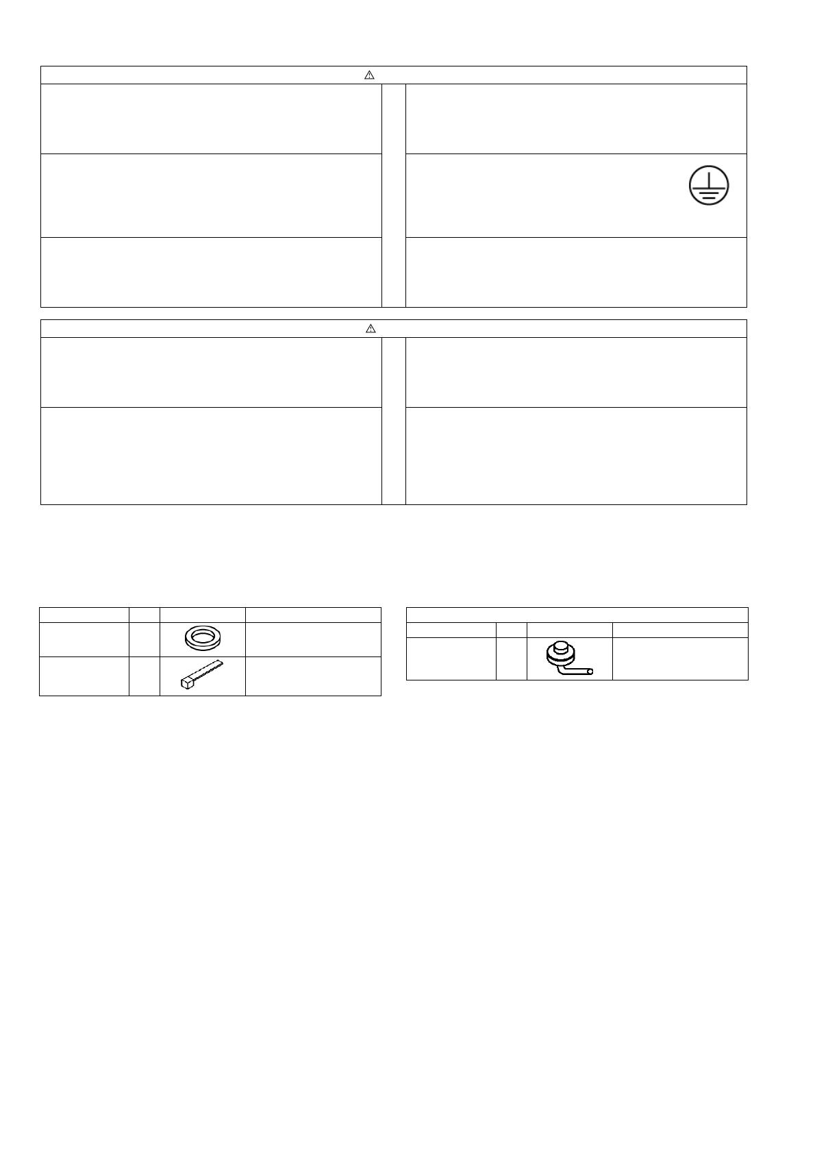
Part name Q’ty Diagram Application
Protective
bushing 2 For protecting electrical
wires
Banding
strap 3 For tying electrical wires
together
Heat pump-types only
Part name Q’ty Diagram Application
Drain elbow AS 1 For connecting the drain
pipe (with ring seat)


