Page is loading ...


Table of Contents
1、Shape drawing ........................... ........................ ..........1
2. Main technical parameters .................. ................2
3. Use and scope of use ........................... ............. .... 3
4. Instructions for use and operation ............ ... .. 3
4.1 Power switch ........................... .............................. .........4
4.2 Combination lock ........................... .............................. 4
4.3 Handle Monitor ........................... ...................................5
4.4 Emergency reverse switch ........................... ................6
4.5 Do not overload use, the maximum load is 2000KG .......6
4.6 Travel and Braking ........................... ..............................7
4.7 Charging jack ........................... ......................................8
4.8 Vehicle travel steering ........................... .................. 9
4.9 Scale ....................... ............. .... ................... .................10
5. Battery use and maintenance ..............................13
6. Fault code ........................... ................................... ..........14
7. Hydraulic schematics ..................................................15
8. Electrical schematics ........................... .......................16
9. Packaging, shipping ........................... .........................17
10. Warning (Caution) ........................... .............................17
11. Handle assembly ........................... ..............................19
12. Driver components ........................... .........................20
13. Front frame assembly .................... ......................... 21
14. Connecting rod assembly ........................... .......... 22
15. Rear frame assembly ........................... ....... ..............23
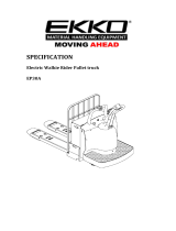
1. Shape drawing
Figure 1-1
1


4.1 Power switch
This pallet truck is equipped with an emergency stop switch,
which is the basic control of this vehicle and is located on the top
of the vehicle body, see Figure 2-1.
Lightly press the emergency stop switch to turn off the power, the
vehicle can not travel. Pull upward, then the button will
automatically move up, i.e., turn on the main power of the vehicle.
Press the off button again, the power is cut off.
Figure 2-1
4.2 Combination lock
The vehicle is equipped with a password lock function, before
entering the authorized password, the machine will not be
allowed to start, in order to prevent unauthorized people from
operating the machine, password lock function can not only
facilitate the use, but also help the machine to prevent theft and
improve security.
Electronic handle handle will enter the standby state after
power on, LCD back light off, according to the handle
configuration, the screen displays the corresponding hour meter
and power information, need to use the correct password to
unlock, then the LCD back light will be lit, in order to manipulate
the vehicle to work normally.
The factory default password for the password lock is 1234, the
operating vehicle can directly use this password to start the
vehicle, the factory default administrator password is 3232, refer
to the following steps to enter and change the password.
4
In standby mode, enter 1234 and press √ to confirm, you
can enter X to rewind one character if you make a mistake.
To change the password in standby mode, enter 3232 and
press the √ key to confirm.
Enter the original password and press the √ key to
confirm.
Enter the new password again and press the √ key to
confirm, the original password will be overwritten.
If you forget your password, you can use the security code
to reset your password.
In standby, enter 123 and press √ to confirm.
Then enter 123 and press √ to confirm, the password is
reset to 1234
4.3 Handle display
Figure 2-2 Figure 2-3
Battery charge indication.
Figure 2-2 shows the display after the battery is
discharged. The last two cells flash when the battery is at its
lowest level and needs to be charged in time.
As Figure 2-3 shows the battery full cell (10 cells) each cell
represents 10% of the power, as the battery is discharged, the
number of cells shown gradually decreases.
5
Emergency
stop switch

Turtle speed: Under normal circumstances, turtle
speed is in the state of no display, press the turtle speed button,
the display shows turtle, at this time for the vehicle turtle speed
state, speed deceleration mode, the
Wrench: When the wrench is displayed, the need for
repair and right fault code flashing is displayed.
Hourglass: When the hourglass symbol flashes, it is in
working condition, at which time the hour meter starts to
count.
4.4 Emergency reverse switch
The red button at the top of the handle is the emergency
reverse switch, as shown in Figure 2-3.
The emergency reverse switch prevents the operator from
being crushed. Press the button and the vehicle slows down
and begins to travel a distance to the rear BW and then stops.
Figure 2-3
4.5, please do not use overload, the maximum load
is 2000KG
Up, down switch and horn button, see Figure 2-4
Up button is located in the middle of the upper part of the tiller
as shown in the figure, press this switch, the fork for rising
movement.
6
The lowering button is located in the lower middle of the tiller
as shown in the figure, press this switch, the fork for lowering
movement.
The horn button is located above the middle of the tiller as
shown in the picture, press this switch to pronounce the horn.
Figure 2-4
4.6 Traveling and braking (as in Figure 2-5)
The handle is divided into three areas A, B and C in the vertical
plane.
If the handle is in area A or C, the vehicle is under braking.
Moving the handle to area A or C while driving puts the vehicle
under emergency braking.
Move the handle to operation area B, the vehicle is in normal
travel. Move the gas pedal knob to the 0 position or release this
knob, regenerative braking is activated and the vehicle brakes
to a stop.
Turn the gas pedal knob to the direction forward FW. or
backward BW. and carefully turn the gas pedal knob to control
the driving speed until the desired speed is reached.
If the gas pedal knob is returned to the middle position, the
controller decelerates the vehicle until it stops.
Move the handle to the A area, press the turtle speed button to
enter the turtle speed driving mode, rotate the acceleration
knob will drive at a slow speed, press the turtle speed button
again, it will return to the original state.
7

Figure 2-5
4.7 Charging jack
The charging port is located on the right side of the vehicle,
as shown in Figure 2-6, and is related to the charger placed in
the vehicle.
The car is an external charger, that is, there is no charger in
the vehicle, charging port for the two-prong socket, charging
with the need for an external charger, the charging port should
be connected with the external charger of the compatible plug.
It can only be charged with the included charger.
Before using the charger, please fully understand the
contents of the instruction manual of the charger.
Please observe these rules.
The charging area must be well ventilated.
8
Figure 2-6
4.8 Vehicle driving steering
The direction of vehicle travel is controlled by the handle.
See Figure 2-7 shows
a Turn the handle in a flat direction to the left and the
vehicle turns left.
b Turn the handle in a flat direction to the right and the
vehicle turns right.
Figure 2-7
9
Charging
socket

4.9 Scale
4.9.1Main Function
》Basic weighing functions: zeroing, tare function
》Accumulation function
》Printer
》Unit exchange function
》Checkweighing function
》Battery voltage indication
》Auto power off and power saving function
4.9.2Parameters
》Sensor excitation voltage:+3.3VDC
》A/D exchange rate:10 次/秒
》Input Signal Range:0—12.8Mv
》Load capacity: up to four 350 ohm sensors
》Unit:KG
》Calibration divisions:3000e
》Selectable indexing values:1/2/5/10/20/50
》Indicator:LCD
》Keyboard: 5 function keys
》Working Temp.:-10~40℃
》Storage Temp.:-20~+60℃
10
4.9 Key function
Key icon
Key name
Key function
ON/OFF
Long press 3 seconds for starting up when the
instrument is in OFF status. Long press for 3 seconds
for shutdown when the instrument is in ON status.
Accumulation
key
1.Accumulation operation
2.See the cumulative sums with SET key
Unit key
Unit switch between Kg and Ib.
Zero setting
key
The instrument has zero clearing within allowable
zero clearing range. Tare beyond the zero clearing
range. Article weight is the tare and displays the net
weight zero.
Function key
1. Calibration with switch key combination
2.Long press for print.
3.Cumulative sum with TOTAL key combination
4.9.1 ON/OFF
Press ON/OFF key for 3 seconds in OFF status. The instrument
will display 888888. It then will have self checking of the
number of strokes. The instrument will display the current
weight after the self-checking.
4.9.2 Zero setting
Press the zero setting tare function if it exceeds the zero range.
The instrument will display the net weight zero. The
instrument is not able to have tare operation when the scale is
in dynamic status and the stable light is not on.
11

The current weight of the instrument will be cleared to zero
and the instrument will display the gross weight zero when the
zero setting key is pressed with permissible range of zero
setting. The instrument cannot be cleared to zero when the
scale is in the dynamic status and the stable light is not on.
4.9.3 Unit switch
Press the unit key for the weight switch between kg and Ib
when C12=1. It is invalid to press the unit key when C12=0.
4.9.4 Print
Press the function key for 1 second and output the current
weight from the serial port in data stabilization.
4.9.5 Accumulative total
Accumulative total of the several weighing data.
4.9.6 Cumulative operation
Load the weighted object on the weighing platform in zero
position to reach a stable state. Press the "cumulative" key to
enter the cumulative status. It will display n001 and then the
weight this time. Then unload the weighted object. Then reload
the weighted object to reach the weighing status after it
returns to the zero position. Press "cumulative" button. It will
display n002 and weight this time. It will reach 999
accumulative total after the cyclic operation.
12
5. The use and maintenance of the battery
1, timely replenishment of electricity, to ensure that the
battery is in a full state of charge, do not let the battery power
consumption to the vehicle can not move before considering
charging, excessive discharge will damage the battery.
2, often check whether the connection parts are solid, the
terminal surface is clean, to ensure good contact.
3,When cleaning the surface of the battery, please do not
use dry cloth and fiber wipe, in order to prevent the generation
of static electricity and cause an explosion.
4,It is strictly forbidden to put metal conductive objects
near the battery terminals to avoid short-circuiting and firing of
both poles and burning the battery.
5,It is forbidden to use the method of battery short circuit
firing to check whether the battery has power.
6, long-term use, the battery should be removed or
disconnected from the negative battery wire. The battery
should be fully charged and stored in a dry, frost-free place.
Once a month, the battery needs to be balanced and
replenished to ensure that the battery can be put into use at
any time.
7,Please use the charger that comes with the car, do not
use other chargers, otherwise it will damage the battery.
8,Prevent the external mechanical force from hurting the
battery.
9,Replace the battery should be consistent with the original,
random replacement may be harmful to the vehicle.
10,Waste battery disposal must strictly comply with the
local regulations recycling treatment, shall not be arbitrarily
discarded.
13

6. Fault codes
Fault
Code
Fault
Possible causes of failure
Solution
20E002
Short circuit,
overcurrent
Parking brake
Check the motor connection for short
circuit; check the motor insulation; replace
the driver;
20E003
High pressure
Parking brake
Check if the battery specification matche;
20E004
Abnormally
high pressure
Parking brake
Avoid slamming downhill braking with
heavy loads;
20E005
Low pressure
Parking brake;After the handle is
reset, the next operation is performed
at a lower speed;
Check battery voltage and charger
20E006
Abnormally
low pressure
Parking brake
Check battery voltage and charger;Check
the battery cable, whether it is loose
20E007
High temp
Parking brake;After the handle is reset,
run at lower speed and lower torque;If
the temperature is lower than the
alarm value, the handle will be reset
and normal operation will resume;
Avoid exposing the pallet truck to high
temperatures; avoid prolonged overloads
20E011
Overcurrent,
loss of control
Parking brake
Check the motor and encoder connection;
whether to match the motor; replace the
driver;
20E012
Overload
Parking brake;After the set time and
the handle is reset, normal operation is
resumed after the alarm value is lower
than the alarm value;
Avoid prolonged overload;
Verify that the driver and motor are
adaptive;
20E013
Blocking and
turning
Parking brake
Check whether the drive wheel is stuck,
etc.; check the motor V, W connection
sequence;
20E014
phase break
Parking brake
Please check the motor connection
20E019
Holder
disconnection
Parking brake
Check the brake holder connection
20E020
Holder Short
circuit
Parking brake
20E021
Encoder Hall
signal
abnormal
Parking brake
Check encoder wire; Replace encoder;
Replace driver; Replace drive wheel
20E026
Abnormal
accelerator
command
signal
Parking brake
Handle signal is not in the normal setting
range; handle type setting of the driver
parameter error; check the connection
between the handle and the driver
20E029
Anti-Flyer
Parking brake;When the handle is
released back to the neutral position, it
will return to normal
The handle is not in neutral position when
the power is turned on or after emergency
reverse operation
20E032
Handle CAN
communication
abnormality
Parking brake
Confirm the connection; confirm whether
the parameter settings match
14
7. Hydraulic schematic
Hydraulic schematic
15

8. Electrical schematic
16
9. Packaging, transportation
The vehicle is packed in palletized wooden boxes, which
are not allowed to be overturned or inverted during
transportation, and are not allowed to collide when lifting and
loading, and do not damage the outer surface of the vehicle
when unpacking.
10 . Warning (Caution)
(1) Before operating the car, please read the instructions and
get familiar with the performance of the car.
(2) To avoid damage to the goods and the car, please do not
press the up-down button or switch the up-down button
quickly and frequently while the car is running.
(3) This car is an electric cart without the need for rapid and
high frequency form shaking the handle!
(4) Do not load heavy objects onto the forks in a hurry!
(5) strictly prohibit the use of overload, do not carry additional
weight, do not exceed the operating load, the chances of
accidents occurring in this behavior is high.
(6) The center of gravity of the cargo should be among the two
forks, otherwise it may damage the forks or cause the cargo to
fall down during operation.
(7) Loose or unstable cargo is not allowed to be loaded!
(8) Do not rest the cargo on the car for a long time!
(9) is strictly forbidden to make sharp turns in narrow passages,
when you should slow down and turn slowly to ensure the
safety of people and goods.
(10) When the truck is not in use, the forks should be lowered
to the lowest position.
(11) It is strictly forbidden to place any part of the body under
heavy objects and forks!
(12) This truck is suitable for use on flat ground or flat working
platform, and long-term parking on slopes is strictly prohibited.
17

(13) Overload or over-ramp operation is strictly prohibited.
Otherwise, it will cause wheel slippage and damage the wheels
and motor as well as the cargo and personal safety.
(14) the vehicle socket should avoid showering rain, once
encountered water intrusion, should be promptly wipe clean.
(15) Use of the vehicle below low voltage is strictly prohibited.
(16) The vehicle is strictly forbidden to connect directly to
external AC power unless it has a built-in charger.
(17) This car is a walking electric truck, for your image and
safety, please do not drive.
(18) without training, it is strictly prohibited to repair
themselves.
18
11、Handle assembly
Number
Name
Quantity
Remarks
101
Screws
4
102
Handle
1
103
Handle bar
1
104
Long Sales
1
105
Line Holder
1
106
Screws
2
107
Bushing
2
108
Pins
1
109
Sensor board
1
110
Screws
1
111
Shaft stop
1
112
Shaft stop
1
113
Short axis
1
114
Gas Spring
2
115
Washers
1
116
Screws
1
19

12、Drive components
Numb
er
Name
Quantity
Remarks
Number
Name
Quantity
Remar
ks
201
Pins
1
213
Screws
2
202
Shaft stop
2
214
Proximity
Switches
1
203
Piston rod
1
215
Nuts
4
204
Screws
2
216
Screws
4
205
Small cover
shell
1
217
Electric
control
1
206
Dust ring
1
218
Press board
1
207
Guide Belt
1
219
Screws
4
208
Seals
1
220
Adjustment
pads
1
209
S Screws
1
221
Screws
4
210
Horn
1
222
Drive Block
1
211
Screws
4
223
Drive
assembly
1
212
Cylinder
barrel
1
20
13、Front frame assembly
Numbe
r
Name
Quantit
y
Remarks
Numb
er
Name
Quantity
Remarks
301
Screws
4
310
Bearings
1
302
Switch
1
311
Bearings
1
303
Nuts
4
312
Pins
2
304
Switch
1
313
Screws
4
305
Baffle
1
314
Shaft stop
2
306
Screws
2
315
Support bar
2
307
Support seat
1
316
Screws
6
308
Screws
2
317
Surrounding
frame
2
309
Front Cover
1
21

14、Connecting rod assembly
Number
Name
Quantity
Remarks
Number
Name
Quantity
Remarks
401
Pins
2
411
Bushing
4
402
Connection
head
2
412
Wheel carrier
2
403
Connecting
rod
assembly
2
413
Bushing
4
404
Shaft stop
2
414
Flexible pins
6
405
Flexible pins
4
415
Pins
2
406
Pins
2
416
Pins
2
407
Bushing
4
417
Screws
2
408
Connection
plate
4
418
Fork Wheel
2
409
Bearings
4
419
Nuts
2
410
Fork Wheel
4
22
15、Rear frame assembly
Numb
er
Name
Quanti
ty
Remarks
Numb
er
Name
Quantity
Remarks
501
Combination Gasket
1
518
Washers
2
502
Connector
1
519
cover
1
503
Oil pipe
1
520
Retainer
2
504
Combination Gasket
2
521
Pin
1
550/685
505
Hollow bolt
1
522
rocker
1
550/685
506
Butterfly Nut
2
523
External hexagon
2
507
Pressure plate
2
524
roller
2
508
hook
2
525
nut
2
509
Rubber pad
8
56
Plate
1
510
battery
4
527
Stud
4
511
pump
1
528
nut
4
bushing
512
Gauge
1
529
Sensor
4
513
Gauge box
1
530
Hexagonal
8
514
Hexagonal
8
531
Screws
2
515
Printer
1
532
Emergency stop
1
516
Connet frame
1
533
Fork frame
1
517
Screws
2
534
Limited plate
1
23
/