
Dell PowerEdge R910 Systems
Information Update

Notes, Cautions, and Warnings
NOTE: A NOTE indicates important information that helps you make better use of
your computer.
CAUTION: A CAUTION indicates potential damage to hardware or loss of data if
instructions are not followed.
WARNING: A WARNING indicates a potential for property damage, personal
injury, or death.
____________________
Information in this publication is subject to change without notice.
© 2010–2011 Dell Inc. All rights reserved.
Reproduction of these materials in any manner whatsoever without the written permission of Dell Inc.
is strictly forbidden.
Trademarks used in this text: Dell™, the DELL logo, and PowerEdge™ are trademarks of Dell Inc.
Intel
®
is a registered trademark of Intel Corporation in the U.S. and other countries. Microsoft
®
,
Windows
®
, and Windows Server
®
are registered trademarks of Microsoft Corporation in the United
States and/or other countries. Broadcom
®
is a registered trademark of Broadcom Corporation and/or
its subsidiaries in the United States and certain other countries. Red Hat Enterprise Linux
®
and
Enterprise Linux
®
are registered trademarks of Red Hat, Inc. in the United States and other countries.
Other trademarks and trade names may be used in this publication to refer to either the entities claiming
the marks and names or their products. Dell Inc. disclaims any proprietary interest in trademarks and
trade names other than its own.
April 2011 Rev. A01

Information Update 3
Power Supply Removal Updates
The I/O riser with 10G network port requires a minimum of two power
supplies to provide standby power to the system. If you remove AC power
cables from the system while DC power is on, the system may momentarily
operate below the minimum power supply requirement. The BMC SEL may
record VR2/IO riser power not good errors and/or PCIe fatal errors when the
system AC power input falls below the minimum requirement.
NOTE: These errors do not affect the system functionality.
To prevent these errors, ensure the following:
• The system operates with a minimum of two power supply units.
• Turn off the system before removing or connecting AC power cables to the
system.
System Limitations With an Optional 10 GbE I/O
Riser
The 10 GbE I/O riser provides two 10 Gb SFP+ ports using a Broadcom
57711 controller in addition to two 1 GbE ports. The following are the
limitations with the 10 GbE I/O riser:
• To ensure system power redundancy, the 10 GbE I/O riser requires all four
power supplies to be connected to the AC power source. The system power
becomes non-redundant if one of the power supplies is removed.
CAUTION: A power supply failure or removal of another power supply after the
system power becomes non-redundant can lead to a system failure and result in
loss of data.
• Wake On LAN (WOL) is not supported on the 10 Gb
SFP+
ports due to
Broadcom 57711 design limitations. However, WOL is supported on the
two 1
GbE ports available on the riser.

4 Information Update
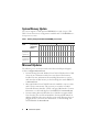
System Memory Update
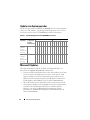
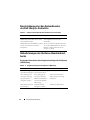
The system supports 32 GB quad-rank RDIMMs for a total of up to 2 TB.
Table 1 shows the memory configurations available with 32 GB RDIMMs in a
four-processor system.
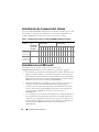
Table 1. Memory Configuration With 32 GB RDIMMs per Processor
Microsoft Updates
The following issues are documented on the Microsoft Help and Support
website at support.microsoft.com:
• Systems running Microsoft Windows Server 2003 or Windows Server 2008
cannot be set to hibernation if they have more than 4 GB of memory
installed. For more information about enabling hibernation on systems
with more than 4 GB of memory, see the knowledge base article KB888575
at
microsoft.com
.
• Microsoft Windows Server 2008 R2 cannot be installed or run on systems
with 1 TB of system memory. This issue may occur either in Unified
Extensible Firmware Interface (UEFI) or in legacy BIOS modes. For more
information, see the knowledge base article KB980598
at
microsoft.com
.
• Systems running Microsoft Windows Server 2008 do not support iSCSI
boot when they have an SD card installed in the internal SD module. In
addition, iSCSI boot does not work when an external USB storage device is
plugged into the system. For more information, see the knowledge base
article KB968410 at
microsoft.com
.
Memory
Mode
Total Memory
(per processor)
/ Total System
Memory
Riser A (memory capacity in GB) Riser B (memory capacity in GB)
1
5
2
6
3
7
4
8
1
5
2
6
3
7
4
8
Power and
performance
optimized
256 GB / 1 TB 32 32 32 32 32 32 32 32
Power and
performance
optimized
512 GB / 2 TB 32 32 32 32 32 32 32 32 32 32 32 32 32 32 32 32

Information Update 5
Flash Memory
The VFlash media provided by Dell is not partitioned to support the iDRAC6
Enterprise virtual flash feature. When you use the virtual flash feature for the
first time, you are prompted to format the media using the iDRAC GUI.
Red Hat Enterprise Linux 5.4 Address Limitation
With 1 TB (When Memory RAS Mode is Not Used)
Red Hat Enterprise Linux 5.4 has an address limitation with 1 TB of system
memory. To install Red Hat Enterprise Linux 5.4, use the mem=1024G boot
time switch. The system does not boot to the operating system unless a boot
time switch mem=1024G is used. For more information, see the knowledge
base article at kbase.redhat.com/faq/docs/DOC-25412.
Microsoft Windows Server 2003 R2 SP2 (x64)
Edition With SP2 Limitation With 1 TB System
Memory (When Memory RAS Mode is Not Used)
The system does not boot to the operating system with 1 TB of system
memory. To resolve this issue, set the memory RAS mode to sparing or mirror.
After installing the operating system, add a boot time switch mem=1046528
or /burnmemory=2048 in the boot.ini file before disabling the RAS mode
for subsequent boots.
MAC Address Labels
For security reasons, the embedded NIC and iDRAC6 Enterprise MAC
address labels provided with your system cannot be affixed after they have
been removed.
NOTE: The labels are located on the system identification panel on the front of the
system.

6 Information Update
System Limitations With an Optional PCIe Riser
The PCIe riser expands the number of PCIe expansion slots available in the
system to 10. Due to the limitation of 64 KB I/O address space on the Intel
IA32 architecture and the I/O granularity of 4 KB set by the PCI bridge
specification, you can exceed the maximum available I/O resources if you
populate the slots with adapters which require more than 4 KB of I/O address
space. The system does not complete POST if 64 KB I/O address space is
exceeded. For more information on supported adapters, see the Dell
PowerEdge R910 Hardware Owner's Manual at support.dell.com/manuals.
Dell Update Package Information
During the Dell Update Package (DUP) installation process, you may see
messages related to the following:
• Request for system reboot before the DUP installation is complete
• Windows hardware detection
• Windows hardware configuration problem
• Re-enumeration of VFlash and momentary drive letter changes in
Windows
It is recommended that you disable the OS Watchdog Timer in the system
BIOS when running the BIOS DUP. The system may reboot in the middle of
an update and result in corrupted flash if:
•The
OS Watchdog Timer
in the system BIOS is enabled
• The timer expires (if set too short)
NIC Teaming
The system has Broadcom embedded NICs that can be teamed with other
vendors such as Intel. It is recommended that you use Broadcom teaming
driver.

Information Update 7
Dell PERC H800 Storage Adapter Slot Limitation
(With PERC H700i as the Internal Storage
Controller)
The system supports up to two PERC H800 adapters. There is no slot
limitation when only one H800 adapter is installed. However, when you install
two H800 adapters in a system with a PERC H700i internal storage adapter,
one of the H800 adapters must be installed in slot 7 (x16 Gen 2 slot). If you
run embedded system diagnostics without an H800 adapter installed in slot 7,
a software error occurs.
Under the same condition, if you enable Collect System Inventory on Restart
(CSIOR), you may not be able to boot to the operating system. You can
enable/disable CSIOR through the iDRAC Configuration Utility by pressing
<Ctrl><E> during boot up. For more information, see the iDRAC User’s
Guide at support.dell.com/manuals.
Dell Lifecycle Controller System Services
Limitations
Table 2. Lifecycle Controller System Services Issues
Issue Recommended Action
SAS6/iR or PERC H200 has virtual disks
in an inactive or non-optimal state.
Make the virtual disks active before
booting to
Lifecycle Controller.
PERC H200 or 6 Gbps SAS HBA are
configured with two virtual disks.
This is a known issue. Do not create
multiple virtual disks using either PERC
H200 or 6 Gbps SAS HBA.

8 Information Update
Hardware Owner’s Manual Updates
BIOS Setup Options Default Settings Update
Power Supply Redundancy Mode (With a 10 Gb I/O Card)
For a redundant system configuration with a 10 Gb I/O card and four power
supplies, the redundancy mode is 2+1.
System Memory
Follow the procedure given below for installing and removing the memory
modules if your system has a memory riser as shown in
Figure 1
.
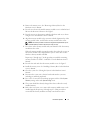
Installing Memory Modules
WARNING: The memory modules are hot to the touch for some time after the
system has been powered down. Allow time for the memory modules to cool
before handling them. Handle the memory modules by the card edges and avoid
touching the components on the memory module.
CAUTION: Many repairs may only be done by a certified service technician.
You should only perform troubleshooting and simple repairs as authorized in your
product documentation, or as directed by the online or telephone service and
support team. Damage due to servicing that is not authorized by Dell is not covered
by your warranty. Read and follow the safety instructions that came with the
product.
1
Turn off the system, including any attached peripherals, and disconnect
the system from the electrical outlet.
2
Open the system. See "Opening the System" in the
Hardware Owner’s
Manual
.
Table 3. Default Settings for BIOS Setup Options
Screen Option Default Option
Memory Settings System Memory Testing Disabled
Power Management Power Management Active Power Controller
Integrated Devices SR-IOV Global Enable Disabled
SATA Settings Embedded SATA ATA Mode

Information Update 9
3
Remove the memory risers. See "Removing a Memory Riser" in the
Hardware Owner’s Manual
.
4
Press the two release tabs until the memory module cover is unlatched and
lift it in the direction of the arrow. See
Figure 1.
5
Press the ejectors on the memory module socket down and out, as shown
in Figure 3-9 in the
Hardware Owner’s Manual
.
6
Align the memory module's edge connector with the alignment key of the
memory module socket, and insert the memory module in the socket.
NOTE: The memory module socket has an alignment key that allows you to
install the memory module in the socket in only one way.
7
Press down on the memory module with your thumbs to lock the memory
module into the socket.
When the memory module is properly seated in the socket, the ejectors on
the memory module socket align with the ejectors on the other sockets
that have memory modules installed.
Repeat step 5 through step 7 of this procedure to install the remaining
memory modules. See Table 3-1 and Table 3-2 in the
Hardware Owner’s
Manual
.
8
Press the four tabs and close the memory module cover. See Figure 2.
9
Install the memory risers. See "Installing a Memory Riser" in the
Hardware
Owner’s Manual
.
10
Close the system. See "Closing the System" in the
Hardware Owner’s
Manual
.
11
Reconnect the system to its electrical outlet and turn the system on,
including any attached peripherals.
12
Press <F2> to enter the System Setup program, and check the
System
Memory
setting on the main
System Setup
screen.
13
The system should have already changed the value to reflect the newly
installed memory.
14
If the value is incorrect, one or more of the memory modules may not be
installed properly. Repeat
step 2 through step 13 of this procedure to
ensure that the memory modules are firmly seated in their sockets.

10 Information Update
15
Run the system memory test in the system diagnostics. See "Running the
Embedded System Diagnostics" in the
Hardware Owner’s Manual
.
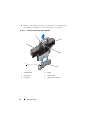
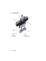
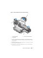
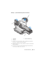
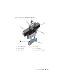
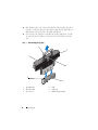
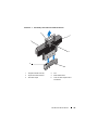
Figure 1. Installing and Removing a Memory Module
1 release tabs (2) 2 handle
3 memory riser 4 release button
5 card guide 6 memory-riser connector
1
3
2
4
5
6

Information Update 11
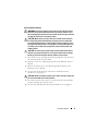
Removing Memory Modules
WARNING: The memory modules are hot to the touch for some time after the
system has been powered down. Allow time for the memory modules to cool
before handling them. Handle the memory modules by the card edges and avoid
touching the components on the memory module.
CAUTION: Many repairs may only be done by a certified service technician.
You should only perform troubleshooting and simple repairs as authorized in
your product documentation, or as directed by the online or telephone service
and support team. Damage due to servicing that is not authorized by Dell is not
covered by your warranty. Read and follow the safety instructions that came
with the product.
CAUTION: To ensure proper system cooling, memory-module blanks must be
installed in any memory socket that is not occupied. Remove memory-module
blanks only if you intend to install memory modules in those sockets.
1
Turn off the system, including any attached peripherals, and disconnect
the system from the electrical outlet.
2
Open the system. See "Opening the System" in the
Hardware Owner’s
Manual
.
3
Remove the memory risers. See "Removing a Memory Riser" in the
Hardware Owner’s Manual
.
4
Press the tabs in the direction of the arrows and lift the memory
module
cover. See Figure 2.
CAUTION: Handle each memory module only on either card edge, making sure
not to touch the middle of the memory module.
5
Press down and out on the ejectors on each end of the socket until the
memory module pops out of the socket.
6
Press the four tabs and close the memory module cover. See Figure 2.

12 Information Update
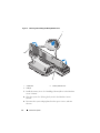
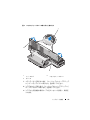
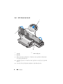
Figure 2. Removing and Installing the Memory Module Cover
7
Install the memory risers. See "Installing a Memory Riser" in the
Hardware
Owner’s Manual
.
8
Close the system. See "Closing the System" in the
Hardware Owner’s
Manual.
9
Reconnect the system and peripherals to their power sources, and turn
them on.
1 release tab 2 memory module cover
3 tabs (4)
2
1
3
Page is loading ...

注、小心和警告
注:“注”表示可以帮助您更好地使用计算机的重要信息。
小心:“小心”表示如果不遵循说明,就有可能损坏硬件或导致数据
丢失。
警告:
“警告”表示可能会导致财产损失、人身伤害甚至死亡。
____________________
本出版物中的信息如有更改,恕不另行通知。
© 2010
–
2011 Dell Inc.
版权所有,翻印必究。
未经
Dell Inc.
书面许可,严禁以任何形式复制这些材料。
本文中使用的商标:
Dell
™、
DELL
徽标、和
PowerEdge
™
是
Dell Inc.
的商标。
Intel
®
是
Intel
Corporation
在美国和其它国家
/
地区的注册商标。
Microsoft
®
、
Windows
®
和
Windows
Server
®
是
Microsoft Corporation
在美国和
/
或其它国家
/
地区的注册商标。
Broadcom
®
是
Broadcom Corporation
和
/
或其子公司在美国和其它特定国家
/
地区的注册商标。
Red Hat
Enterprise Linux
®
和
Enterprise Linux
®
是
Red Hat, Inc.
在美国和其它国家
/
地区的注册商标。
本文件中述及的其它商标和商品名称是指拥有相应标记和名称的公司或其制造的产品。
Dell Inc.
对不属于自己的商标和商品名称不拥有任何专有权。
2011
年
4
月
Rev. A01
Page is loading ...

16 信息更新
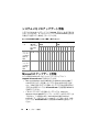
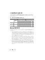
系统内存更新
系统支持
32 GB
四列
RDIMM
,支持的最大总容量为
2 TB
。
表
1
显示了四
处理器系统中
32 GB RDIMM
的内存配置。
表
1.
每个处理器
32 GB RDIMM
的内存配置
Microsoft
更新
以下问题已记录到
Microsoft
帮助和支持网站
support.microsoft.com
:
•
如果运行
Microsoft Windows Server 2003
或
Windows Server 2008
的系
统安装有
4 GB
以上的内存,则不能设置进入休眠模式。有关在安装有
4 GB
以上内存的系统中启用休眠的详情,请参阅
microsoft.com
上的
知识库文章
KB888575
。
• Microsoft Windows Server 2008 R2
不能安装或运行在具有
1 TB
系统内
存的系统上。此问题可能在统一可扩展固件接口
(UEFI)
中或在传统
BIOS
模式下出现。有关详情,请参阅
microsoft.com
上的知识库文章
KB980598
。
•
如果运行
Microsoft Windows Server 2008
的系统在内部
SD
模块中安装
有
SD
卡,则不支持
iSCSI
引导。此外,当外部
USB
存储设备插入系
统时,
iSCSI
引导无法工作。有关详情,请参阅
microsoft.com
上的知
识库文章
KB968410
。
内存模式
内存总容量
(每个处理器)
/
系统内存总容量
提升卡
A
(以
GB
为单位的内存
容量)
提升卡
B
(以
GB
为单位的内存
容量)
1
5
2
6
3
7
4
8
1
5
2
6
3
7
4
8
电源和性能
优化
256 GB / 1 TB 32 32 32 32 32 32 32 32
电源和性能
优化
512 GB / 2 TB 32 32 32 32 32 32 32 32 32 32 32 32 32 32 32 32

信息更新 17
快擦写存储器
Dell
提供的
VFlash
介质未进行分区,无法支持
iDRAC6 Enterprise
虚拟闪速
更新功能。首次使用虚拟闪速更新功能时,系统会提示您使用
iDRAC GUI
格式化介质。
Red Hat Enterprise Linux 5.4
使用
1 TB
内存时的
地址限制(未使用内存
RAS
模式时)
Red Hat Enterprise Linux 5.4
使用
1 TB
系统内存时有地址限制。要安装
Red
Hat Enterprise Linux 5.4
,请使用
mem=1024G
引导时间开关。除非使用引
导时间开关
mem=1024G
,否则系统不会引导至操作系统。有关详情,请参
阅
kbase.redhat.com/faq/docs/DOC-25412
上的知识库文章。
Microsoft Windows Server 2003 R2 SP2 (x64)
Edition
(含
SP2
)使用
1 TB
系统内存时的限制
(未使用内存
RAS
模式时)
使用
1 TB
系统内存的系统没有引导至操作系统。要解决此问题,请将
内存
RAS
模式设置为
sparing
(备用)或
mirror
(镜像)。安装操作系
统之后,在
boot.ini
文件中添加引导时间开关
mem=1046528
或
/burnmemory=2048
,然后对后续引导禁用
RAS
模式。
MAC
地址标签
为安全起见,随系统提供的嵌入式
NIC
和
iDRAC6 Enterprise MAC
地址标
签在撕下后将不能再次粘贴。
注:这些标签位于系统正面的系统识别面板上。

18 信息更新
使用可选
PCIe
提升卡的系统限制
PCIe
提升卡将系统中可用的
PCIe
扩充槽数扩充为
10
个。由于
Intel IA32
体
系结构中的
64 KB I/O
地址空间限制和按照
PCI
桥接器规格设置的
4 KB I/O
单位,如果您在插槽中插入需要超出
4 KB I/O
地址空间的适配器,则可能
会超出最大可用
I/O
资源限制。如果超出
64 KB I/O
地址空间限制,系统不
会完成
POST
。有关支持的适配器的详情,请参阅
support.dell.com/manuals
上的《
Dell PowerEdge R910 Hardware Owner's Manual
》(
Dell PowerEdge
R910
硬件用户手册)。
Dell Update Package
信息
在安装
Dell Update Package (DUP)
的过程中,您可能会看到与下列情况相
关的消息:
• Request for system reboot before the DUP installation is complete
(在
DUP
安装完成之前请求系统引导)
• Windows hardware detection
(
Windows
硬件检测)
• Windows hardware configuration problem
(
Windows
硬件配置问题)
• Re-enumeration of VFlash and momentary drive letter changes in
Windows
(
Windows
中
VFlash
重新枚举和驱动器号临时更改)
运行
BIOS DUP
时,建议您在系统
BIOS
中禁用
OS Watchdog Timer
(操作
系统监护程序计时器)。如果出现以下情况,系统可能在更新过程中间重新
引导并导致损坏快擦写:
•
系统
BIOS
中已启用
OS Watchdog Timer
(操作系统监护程序计
时器)
•
计时器已过期(如果设置的时间过短)
NIC
组队
带有
Broadcom
嵌入式
NIC
的系统可与其他供应商(例如,
Intel
)组队。
建议您使用
Broadcom
组队驱动程序。
Page is loading ...
Page is loading ...
Page is loading ...
Page is loading ...
Page is loading ...
Page is loading ...
Page is loading ...
Page is loading ...
Page is loading ...
Page is loading ...
Page is loading ...
Page is loading ...
Page is loading ...
Page is loading ...
Page is loading ...
Page is loading ...
Page is loading ...
Page is loading ...
Page is loading ...
Page is loading ...
Page is loading ...
Page is loading ...
Page is loading ...
Page is loading ...
Page is loading ...
Page is loading ...
Page is loading ...
Page is loading ...
Page is loading ...
Page is loading ...
Page is loading ...
Page is loading ...
Page is loading ...
Page is loading ...
Page is loading ...
Page is loading ...
Page is loading ...
Page is loading ...
Page is loading ...
Page is loading ...
Page is loading ...
Page is loading ...
Page is loading ...
Page is loading ...
Page is loading ...
Page is loading ...
Page is loading ...
Page is loading ...
Page is loading ...
Page is loading ...
Page is loading ...
Page is loading ...
Page is loading ...
Page is loading ...
Page is loading ...
Page is loading ...
Page is loading ...
Page is loading ...
Page is loading ...
Page is loading ...
Page is loading ...
Page is loading ...
Page is loading ...
Page is loading ...
Page is loading ...
Page is loading ...
Page is loading ...
Page is loading ...
Page is loading ...
Page is loading ...
Page is loading ...
Page is loading ...
Page is loading ...
Page is loading ...
-
 1
1
-
 2
2
-
 3
3
-
 4
4
-
 5
5
-
 6
6
-
 7
7
-
 8
8
-
 9
9
-
 10
10
-
 11
11
-
 12
12
-
 13
13
-
 14
14
-
 15
15
-
 16
16
-
 17
17
-
 18
18
-
 19
19
-
 20
20
-
 21
21
-
 22
22
-
 23
23
-
 24
24
-
 25
25
-
 26
26
-
 27
27
-
 28
28
-
 29
29
-
 30
30
-
 31
31
-
 32
32
-
 33
33
-
 34
34
-
 35
35
-
 36
36
-
 37
37
-
 38
38
-
 39
39
-
 40
40
-
 41
41
-
 42
42
-
 43
43
-
 44
44
-
 45
45
-
 46
46
-
 47
47
-
 48
48
-
 49
49
-
 50
50
-
 51
51
-
 52
52
-
 53
53
-
 54
54
-
 55
55
-
 56
56
-
 57
57
-
 58
58
-
 59
59
-
 60
60
-
 61
61
-
 62
62
-
 63
63
-
 64
64
-
 65
65
-
 66
66
-
 67
67
-
 68
68
-
 69
69
-
 70
70
-
 71
71
-
 72
72
-
 73
73
-
 74
74
-
 75
75
-
 76
76
-
 77
77
-
 78
78
-
 79
79
-
 80
80
-
 81
81
-
 82
82
-
 83
83
-
 84
84
-
 85
85
-
 86
86
-
 87
87
-
 88
88
-
 89
89
-
 90
90
-
 91
91
-
 92
92


Ask a question and I''ll find the answer in the document
Finding information in a document is now easier with AI
in other languages
- français: Dell PowerEdge R910 spécification
- español: Dell PowerEdge R910 Especificación
- Deutsch: Dell PowerEdge R910 Spezifikation
- 日本語: Dell PowerEdge R910 仕様
Related papers
Other documents
-
Quantum DLT-V4 User manual
-
Gigabyte DESIGNARE Memory 64GB (2x32GB) 3200MT/s Installation guide
-
-
Sony VGP-MM512L Operating instructions
-
Emulex Model 375 User manual
-
Mitsubishi Electric A9GTMEM-10MF/20MF/40MF Type Flash PC Card User manual
-
 Magnescale LY71 Owner's manual
