
USER MANUAL
EN
Edition: 2 from 04.04.2019
Supersedes the edition: 1 from 14.02.2019
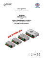
Modules
EN54M series
v.1.0
Power supply modules for built-in
fire alarm systems and smoke
and heat control systems.

www.pulsar.pl EN54M RED POWER plus
2
GENERAL SAFETY RULES
Before installation, read the instruction manual to avoid errors that
can damage the device and give you an electric shock.
Before installation, cut off the voltage in the 230 V power-supply circuit.
To switch power off, use an external switch, in which the distance between the
contacts of all poles in the disconnection state is not less than 3mm.
The shock protection circuit shall be done with a particular care: the yellow and green
wire coat of the power cable should be connected to the terminal marked with
the grounding symbol on the PSU enclosure. Operation of the PSU without the
properly made and fully operational shock protection circuit is UNACCEPTABLE! It
can cause damage to the equipment or an electric shock.
The device should be transported without batteries. This has a direct impact on the
safety of the user and the device.
Installing and connecting the power supply must be carried out without batteries.
When connecting batteries to the power supply, pay particular attention to the correct
polarity. If necessary, it is possible to permanently disconnect the battery from the
power supply systems by removing the F
BAT
fuse.
The power supply is adapted to be connected to a power distribution network with an
effectively earthed neutral conductor.
Ensure a free, convection air flow around the enclosure. Do not cover the ventilation
openings.

www.pulsar.pl EN54M RED POWER plus
3
TABLE OF CONTENTS
1. PSU FEATURES. .................................................................................................................................... 4
2. FUNCTIONAL REQUIREMENTS OF POWER SUPPLY MODULES. ........................................ 5
3. TECHNICAL DESCRIPTION. ............................................................................................................. 6
3.1. GENERAL DESCRIPTION. ....................................................................................................................................................... 6
3.2. BLOCK DIAGRAM. ................................................................................................................................................................ 6
3.3. DESCRIPTION OF COMPONENTS AND POWER SUPPLY TERMINALS. ........................................................................................ 7
3.4. DIMENSIONS OF POWER SUPPLY MODULES. .......................................................................................................................... 8
4. INSTALLATION. ................................................................................................................................... 9
4.1. REQUIREMENTS. .................................................................................................................................................................. 9
4.2. INSTALLATION PROCEDURE. ................................................................................................................................................ 9
4.3. PROCEDURE FOR CHECKING THE POWER SUPPLY MODULE AT THE PLACE OF INSTALLATION. ............................................ 10
5. FUNCTIONS ......................................................................................................................................... 11
5.1. TECHNICAL OUTPUTS. ........................................................................................................................................................ 11
5.2. INPUT OF COLLECTIVE FAILURE: EXTI. .............................................................................................................................. 12
5.3. INDICATION OF THE ENCLOSURE OPENING - TAMPER. ..................................................................................................... 13
5.4. PSU OVERLOAD. ................................................................................................................................................................ 13
5.5. SHORT-CIRCUIT OF THE PSU OUTPUT. ............................................................................................................................... 13
5.6. ADDITIONAL MODULES. ..................................................................................................................................................... 13
5.6.1 Extending the number of PSU outputs - EN54C-LB4 and EN54C-LB8 fuse modules. ................................................ 13
5.6.2 Cooperation with electric actuators - EN54C-LS4 and EN54C-LS8 sequential modules. .......................................... 14
6. RESERVE POWER SUPPLY CIRCUIT. .......................................................................................... 15
6.1. BATTERY DETECTION. ....................................................................................................................................................... 15
6.2. PROTECTION AGAINST SHORT-CIRCUIT OF THE BATTERY TERMINALS. ............................................................................... 15
6.3. PROTECTION AGAINST REVERSE BATTERY CONNECTION. ................................................................................................... 15
6.4. DEEP DISCHARGE BATTERY PROTECTION UVP. ................................................................................................................. 15
6.5. BATTERY TEST. .................................................................................................................................................................. 15
6.6. MEASUREMENT OF THE RESISTANCE OF THE BATTERY CIRCUIT. ........................................................................................ 15
6.7. BATTERY TEMPERATURE MEASUREMENT. ......................................................................................................................... 15
6.8. STANDBY TIME. ................................................................................................................................................................. 16
7. TECHNICAL PARAMETERS. .......................................................................................................... 17
Table 4. Electrical parameters. ............................................................................................................................................ 17
Table 5. Mechanical parameters. ......................................................................................................................................... 18
Table 6. Safety of use. ........................................................................................................................................................... 18
Table 7. Recommended types and sections of installation cables. ....................................................................................... 18
8. TECHNICAL INSPECTIONS AND MAINTENANCE. .................................................................. 19

www.pulsar.pl EN54M RED POWER plus
4
1. PSU features.
Built-in power supply module
In accordance with standards: EN 54-4,
EN12101-10
27,6 V DC uninterruptible power supply
available versions with 2 A/3 A/5 A/10 A current
efficiencies
available versions with space for 7 Ah – 65 Ah
batteries
independently protected outputs AUX1 and AUX2
DIN rail mounting using additional EN54M-DIN1
bracket (optional equipment)
cooperation with EN54C-LB4 and EN54C-LB8 fuse
modules (optional equipment)
cooperation with EN54C-LS4 and EN54C-LS8
sequential modules (optional equipment)
optical indication – LED panel EN54M-LED (option)
high efficiency (up to 89%)
low level of voltage ripple
microprocessor-based automation system
measurement of the resistance of the battery circuit
automatic temperature-compensated charging
automatic battery test
two-stage battery charging process
accelerated battery charging
monitoring of the continuity of the battery circuit
monitoring of the battery voltage
monitoring of charging and maintenance of the
batteries
deep discharge battery protection (UVP)
battery overcharge protection
the LoB low battery voltage indication
battery output protection against short-circuit and
reverse connection
output voltage control
fuse monitoring of AUX1 and AUX2 outputs
relay output of collective failure ALARM
EPS relay output indicating 230 V power loss
the EXTi input of external failure
protections:
SCP short-circuit protection
OLP overload protection
OVP overvoltage protection
Surge protection
convection cooling (forced only in the EN54M-
10Axx)
warranty - 3 years from the production date

www.pulsar.pl EN54M RED POWER plus
5
2. Functional requirements of power supply modules.
Buffer power supply modules for fire alarm systems has been designed in accordance with the following
standards:
- EN 54-4:2001+A1:2004+A2:2007 Fire detection and fire alarm systems.
- EN 12101-10:2007 Smoke and heat control systems.
Functional requirements
Requirements
according to
standards
Power supplies
EN54M series
Two independent power sources
YES
YES
External Power Supply failure indication
YES
YES
Two independent power supply outputs protected against short-circuit
YES
YES
Temperature-compensated battery charging
YES
YES
Measurement of the resistance of the battery circuit
YES
YES
Low battery indication
YES
YES
Recharging the battery to 80% of the rated capacity within 24 hours
YES
YES
Deep discharge battery protection
YES
YES
Short-circuit protection of battery terminals
YES
YES
Charging circuit failure indication
YES
YES
Short-circuit protection
YES
YES
Overload protection
YES
YES
Output of collective failure ALARM
YES
YES
EPS technical output
YES
YES
Low output voltage indication
-
YES
High output voltage indication
-
YES
Indication of power supply failure
-
YES
Overvoltage protection
-
YES
Input of an external failure indication EXTi
-
YES

www.pulsar.pl EN54M RED POWER plus
6
3. Technical description.
3.1. General description.
The power supply modules are designed for mounting in an additional housing. In order to meet
the requirements of the EN54-4 + A1 + A2 and EN12101-10 + AC standards, the enclosure must be of
appropriate construction. IP30 protection class is required.
Buffer power supply modules has been designed for an uninterrupted supply of fire alarm systems,
smoke and heat control systems, fire protection equipment and fire automatics requiring stabilized voltage of
24 V DC (±15%). The power supplies are fitted with two independently protected AUX1 and AUX2 outputs,
which provide a voltage of 27,6 V DC and the total current efficiency depending on the version:
Built-in power supply
module model
Battery
Continuous operation
Imax a
Instantaneous operation
Imax b
EN54M-2A7
EN54M-2A7-17
7,2 Ah
1,6 A
2 A
7÷20 Ah
1,2 A
EN54M-3A7-17
EN54M-3A17-40
7÷20 Ah
2,2 A
3 A
17÷45 Ah
1,2 A
EN54M-5A7-17
EN54M-5A17-40
EN54M-5A40-65
7÷20 Ah
4,2 A
5 A
17÷45 Ah
3,2 A
40÷65 Ah
2,4 A
EN54M-10A17-40
EN54M-10A40-65
17÷45 Ah
8,2 A
10 A
40÷65 Ah
7,4 A
In case of power loss, the PSU switches to battery power, providing uninterruptible power supply.
The power supply modules units works with maintenance-free lead acid batteries made with AGM
technology or gel technology.
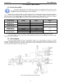
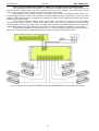
3.2. Block diagram.
The power supply modules has been manufactured based on a high-efficiency system of AC/DC
converter. Applied microprocessor circuit is responsible for the full diagnostics of the PSU parameters and
batteries. The figure below shows a flowchart of the power supply, along with selected functional blocks which
are essential for the proper functioning of the unit.
Fig. 1. Block diagram of the PSU module.

www.pulsar.pl EN54M RED POWER plus
7
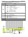
3.3. Description of components and power supply terminals.
Table 1. Elements of the PSU module (Fig. 2).
Component
No.
Description
L-N-PE 230 V power connector with protective terminal
Terminals:
TEMP – input of the battery temperature sensor
TAMPER – input of the microswitch tamper
Closed input = no indication
Open input = alarm
ALARM – technical output of collective failure of the PSU - relay type
EPS – technical output of AC power failure indication
open = AC power failure
closed = AC power - O.K.
EXTi – external failure input
Closed input = no indication
Open input = alarm
+BAT- – terminals for connecting the battery
+AUX1- – AUX1 power output ( - AUX=GND)
+AUX2- – AUX2 power output ( - AUX=GND)
CAUTION! In Fig.2 the set of contacts shows a potential-free status of the relay, which corresponds to
power supply failure.
Fuses:
F
BAT
– fuse in the battery circuit,
F
AUX1
– fuse in the AUX1 output circuit,
F
AUX2
– fuse in the AUX2 output circuit,
The fuse values are given in table 4 - "Electrical parameters".
LEDs – optical indication:
230 V – voltage in the 230 V circuit
APS – battery failure
ALARM – collective failure
AUX1 – AUX1 output voltage (at the AUX1 connector)
AUX2 – AUX2 output voltage (at the AUX2 connector)
PANEL LED – the EN54M-LED external optical indication panel
Battery temperature sensor
Battery connectors; positive: +BAT = red, negative: - BAT = black
Fig. 2. View of the PSU module.

www.pulsar.pl EN54M RED POWER plus
8
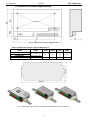
3.4. Dimensions of power supply modules.
Fig. 3. Dimensions of power supply module.
Table 2. Dimensions of power supply modules (Fig. 3).
Power supply module
model
LxWxH
[mm]
L1
[mm]
W1
[mm]
L2
[mm]
W2
[mm]
EN54M-2Ax
200 x 120 x 48
155.5
64
18
41,5
EN54M-3Ax
EN54M-5Ax
204 x 141 x 52
EN54M-10Ax
237 x 168 x 55
186
80,5
26
48,5
Fig. 4. DIN 35mm rail mounting using additional EN54M-DIN1 bracket (optional).

www.pulsar.pl EN54M RED POWER plus
9
4. Installation.
4.1. Requirements.
The power supply modules are designed for mounting in an additional housing. In order to
meet the requirements of the EN54-4 + A1 + A2 and EN12101-10 standards, the enclosure must be of
appropriate construction. IP30 protection class is required.
The power supply module is to be mounted by a qualified installer, holding relevant permits and licenses
(applicable and required for a given country) for 230 V in and low-voltage installations.
As the power supply is designed for a continuous operation and is not equipped with a power-
switch, therefore, an appropriate overload protection in the power supply circuit should be provided. Moreover,
the user should be informed how to disconnect the power supply unit from the mains supply (usually by
assigning an appropriate fuse in the fuse box). One switch should only protect one power supply. The electrical
system shall follow valid standards and regulations. The power supply should operate in a vertical position in
order to provide free and convectional air flow through ventilating holes of the casing.
As the PSU cyclically runs a periodic battery test, during which the resistance in the battery circuit is
measured, pay attention to the proper connection of cables to the terminals. Installation cables should be firmly
connected to the battery side terminals and to the power supply connector. If necessary, it is possible to
permanently disconnect the battery from the power supply systems by removing the F
BAT
fuse.
4.2. Installation procedure.
CAUTION!
Before installation, cut off the voltage in the 230 V power-supply circuit.
To switch power off, use an external switch, in which the distance between the contacts of
all poles in the disconnection state is not less than 3mm.
It is required to install an installation switch with a nominal current of 6 A in the power supply circuits
outside the power supply unit.
1. Install the power supply module in the selected location of the housing.
Connect the power cables ~230 V to the L-N terminals of the PSU. The cable length inside the housing
should not exceed 10 cm. Connect the ground wire to the terminal marked with grounding symbol in
enclosure. Use a three-core cable (with a yellow and green protection wire) to make the connection.
The shock protection circuit shall be done with a particular care: the yellow and green wire
coat of the power cable should be connected to the terminal marked with the grounding
symbol on the PSU enclosure. Operation of the PSU without the properly made and fully
operational shock protection circuit is UNACCEPTABLE! It can cause damage to the equipment or
an electric shock.
2. Connect the receivers’ cables to the AUX1 and AUX2 output terminals.
3. If needed, connect the cables from the devices to the technical inputs and outputs:
- ALARM; technical output of collective failure of the PSU
- EPS; technical output of AC power loss indication
- EXTi; input of collective failure
4. Install the batteries in a designated area of the enclosure. Connect the batteries with the PSU paying
special attention to the correct polarity. Batteries must be connected in series using the special cable
(included). Attach the temperature sensor to any of the batteries with mounting tape (included). Screw
the temperature sensor to the "Temp" terminals of the power supply (Figure 2, point 6). Insert the sensor
between the batteries.
5. Switch on the 230 V supply. The corresponding LEDs on the power supply PCB should be ON: AC
green and connectors AUX1, AUX2.
6. Check the current consumption of the receivers, taking into account the battery charging current, so as
not to exceed the total current efficiency of the PSU (see section 3.1).
7. Once the tests are completed, close the enclosure, cabinet etc.

www.pulsar.pl EN54M RED POWER plus
10
Table 3. Operation parameters.
Environmental class EN 12101-10:2007
2
Protection grade EN 60529: 2003
IP00
Operating temperature
-5
o
C÷75
o
C
Storing temperature
-25
o
C÷60
o
C
Relative humidity
20%...90%, no condensation
Sinusoidal vibrations during operation:
10 ÷ 50 Hz
50 ÷ 150 Hz
0,1 G
0,5 G
Surges during operation
0,5 J
Direct insolation
unacceptable
Vibrations and surges during transport
According to the PN-83/T-42106 standard
4.3. Procedure for checking the power supply module at the place of installation.
1. Check the indication displayed on the front panel of the power supply unit:
a) The 230 V LED should remain lit to indicate the presence of the mains supply voltage.
b) The 230 V AUX 1 and AUX 2 LED should remain lit to indicate the presence of the supply voltage.
2. Check the output voltage after 230 V power failure.
a) Simulate the lack of 230 V mains voltage by disconnecting the main circuit breaker.
b) The 230 V LED should go out.
c) The AUX 1 and AUX 2 LED should remain lit to indicate the presence of the output voltage.
d) The LED ALARM LED will start blinking.
e) The EPS and ALARM technical outputs will change status into opposite after 10s.
f) Turn on the 230 V mains voltage again. Indication should return to the initial status from point 1 after a
few seconds.
3. Check whether the lack of continuity in the battery circuit is properly indicated.
a) During normal PSU operation (230 V mains voltage on), disconnect the battery circuit by disconnecting
the F
BAT
fuse.
b) Within 5 minutes the PSU will start signaling a failure in the battery circuit.
c) The ALARM LED will start blinking.
d) The ALARM technical output will change status into opposite.
e) Turn on the. F
BAT
fuse in the battery circuit again.
f) The power supply should return to normal operation, indicating the initial status, within 5 minutes after
the battery test is completed.

www.pulsar.pl EN54M RED POWER plus
11
5. Functions
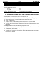
5.1. Technical outputs.
The power supply is fitted with relay indication outputs changing state upon the occurrence of a specific
event.
Fig. 5. Electrical diagram of relay outputs.
EPS - output indicating 230 V power loss.
The output indicates 230 V power loss. Under normal status – with the 230 V supply on, the output
is closed. In case of power failure, the PSU will switch the output into the open position after a time 10s.
Fig. 6. EPS technical output.
CAUTION! In Fig. the set of contacts shows a potential-free status of the relay, which corresponds to
power supply failure.
ALARM - technical output of collective failure indication.
Output indicating collective failure. In the case of 230 V power failure, battery circuit failure, PSU
failure, or EXTi input activation, the collective failure signal ALARM will be generated.
Failure can be triggered by the following events:
- AC power loss
- faulty batteries
- undercharged batteries
- disconnected batteries
- high resistance of the battery circuit
- no continuity in the battery circuit
- U
AUX1, AUX2
output voltage below 26 V
- U
AUX1, AUX2
output voltage over 29,2 V
- battery charging circuit failure
- blown F
AUX1
or F
AUX2
fuse
- PSU overload
- to high battery temperature (>65°C)
- temperature sensor failure, t < -20°C or t > 80°C
- enclosure opening - TAMPER
- internal damage of the PSU
Fig. 7. Technical output ALARM.
CAUTION! In Fig. the set of contacts shows a potential-free status of the relay, which corresponds to
power supply failure.

www.pulsar.pl EN54M RED POWER plus
12
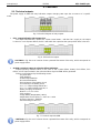
5.2. Input of collective failure: EXTi.
The EXT IN (external input) technical input indicating collective failure is intended for additional, external
devices that generate the failure signal. Disconnection of the EXTi terminals will cause a failure of the PSU and
generate a failure signal at the ALARM output.
The EXTi technical input is not galvanically isolated from the power supply. The "minus" terminal is
connected to the power supply.
The connection of external devices to the EXT IN input is shown in the electrical diagram below. Relay
outputs or "open collector" signal outputs can be used as the signal source.
Fig. 8. Connections to the EXTi input.
The EXTi input has been adjusted to work with EN54C-LB4 and EN54C-LB8 fuse modules generating a
failure signal in case of a fuse fault in any of output sections (see section 5.6.1). To guarantee a correct
cooperation between the fuse module and the EXTi input, the connections shall be made as presented in the
diagram below.
Fig. 9. Example of a connection with the fuse module EN54C-LB8.

www.pulsar.pl EN54M RED POWER plus
13
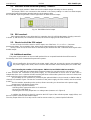
5.3. Indication of the enclosure opening - TAMPER.
The power supply module is fitted with the microswitch tamper indicating enclosure opening.
The tamper cable is not connected to the terminal in the factory settings. In order to activate tamper,
remove the jumper from tamper terminal and plug in the tamper cable.
Each TAMPER input will generate a failure signal at the ALARM technical output.
Fig. 10. TAMPER technical output.
5.4. PSU overload.
If the output overload occurs during the PSU operation, the PSU will limit the battery charging current for
1 minute. If, after this time, the overload is removed, the normal charging mode will be restored.
5.5. Short-circuit of the PSU output.
In case of short-circuit of the AUX1 or AUX2 output, one of the fuses - F
AUX1
or F
AUX2
– becomes
permanently blown. The restoration of the voltage at the output requires the replacement of the fuse.
During a short circuit, the PSU failure is indicated by the ALARM LED and a collective failure signal at the
ALARM output.
5.6. Additional modules.
The power supply module can be used with optional fuse or sequential modules that will increase its
functionality in the case of extended fire protection systems.
When installing the fuse module in the power supply, take into account the current consumption for
the power supply's own needs, which is used for the calculation of the standby time (see section 6.8).
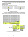
5.6.1 Extending the number of PSU outputs - EN54C-LB4 and EN54C-LB8 fuse modules.
The PSU is fitted with two independently protected outputs for connecting AUX1 and AUX2 receivers.
If more receivers are connected to the power supply, it is recommended to secure each of them with an
independent fuse. Such a solution will allow avoiding the failure of the entire system in the event of a fault (short
circuit on the line) of any of the connected receivers.
The possibility of such protection is provided by the optional EN54C-LB4 (4-channel) or EN54C-LB8 (8-
channel) fuse module. Figure 9 shows the connection of the power supply, the fuse module, and the receivers
(LOAD).
The fuse module, depending on the version, allows connecting 4 or 8 receivers to the power supply.
Output state is indicated by green LEDs.
The blown strip fuse is signaled as follows:
- switching off the appropriate LED: L1 for AUX1 etc.
- the red PSU LED lights up
- switching the PSU relay output into a no-voltage state (contacts as in Figure 9)
In addition, the blown fuse signal is passed to the EXTi input of the collective power supply failure, and
the PSU reports a failure at the ALARM output.
The relay output of the PSU fuse strip can be used for remote control, e.g. external optical indication.

www.pulsar.pl EN54M RED POWER plus
14
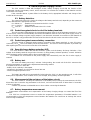
5.6.2 Cooperation with electric actuators - EN54C-LS4 and EN54C-LS8 sequential modules.
The sequential modules are designed for use with electric actuators without return spring (EN54C-LS4)
and with electric actuators with return spring (EN54C-LS8) used for fire dampers and smoke vents. These
devices are used in fire alarm systems and smoke and heat control systems.
When switching on the electric actuator, a short-term current surge, exceeding its rated current, may
occur. If multiple electric actuators are connected, the above-mentioned surge current poses a risk of incorrect
operation of the power supply (e.g. triggering the protection of output circuit), despite not exceeding the current
capacity of the power supply.
The sequential switching module causes the receivers connected to its outputs to be sequentially
switched, with a delay of 100 ms. Thanks to this solution, the surge current is reduced to the value ensuring
correct operation of the power supply. Thus, it enables safe connection of additional actuators. All outputs are
independently protected by PTC polymer fuses and have LED diodes signaling the activation of each output.
The module is controlled by a control device (e.g. a CSP control panel) configuring the resistance at the
INPUT connector. The technical output of failure signals failures at the parametric INPUT input.
Fig. 11. Example of connection of the EN54C-LS8 sequential module with actuators with return spring.

www.pulsar.pl EN54M RED POWER plus
15
6. Reserve power supply circuit.
The PSU module is fitted with intelligent circuits: battery charging circuit with the function of the
accelerated charging and battery control, which main task is to monitor the condition of the batteries and the
connections in the circuit.
If the controller detects a power failure in the battery circuit, appropriate indication and change of the
ALARM technical output.
6.1. Battery detection.
The control unit of the PSU checks the voltage at the battery terminals and, depending on the measured
values, determines the appropriate reaction:
U
BAT
below 4 V - batteries not connected to the PSU circuits
U
BAT
= 4 to 20 V - faulty batteries
U
BAT
over 20 V - batteries connected to the PSU circuits
6.2. Protection against short-circuit of the battery terminals.
The PSU module is fitted with the circuit protecting against short-circuit of the battery terminals. In case
of short circuit, control circuit immediately disconnects the batteries from the rest of the power supply circuit, so
the loss of output voltage on power supply outputs is not observed. Automatic reconnection of the batteries to
the PSU's circuits is only possible after the removal of the short-circuit and correct connection of the circuits.
6.3. Protection against reverse battery connection.
The PSU module is protected against reverse connection of the battery terminals. In case of incorrect
connection, the F
BAT
fuse in the battery circuit becomes blown. The return to normal operation is possible only
after replacing the fuse and correct connection of the batteries.
6.4. Deep discharge battery protection UVP.
The PSU module is fitted with the disconnection system and the battery discharge indication. If the
voltage at the battery terminals drops below 20 V±0.2 V during battery-assisted operation, acoustic indication
will be activated and the batteries will be disconnected within 15s.
The batteries are reconnected to the power supply unit automatically once the 230 V mains supply is
restored.
6.5. Battery test.
The PSU runs battery test every 5 minutes. During testing, the control unit of the PSU measures the
electrical parameters according to the implemented measuring method.
A negative result occurs when the:
- battery circuit continuity is interrupted,
- resistance in the battery circuit increases above 300 mΩ
- terminal voltage drops below 24 V.
The battery test will also be automatically locked when the PSU is in the operating mode, in which the
battery test is impossible. Such condition occurs, for example, during battery assisted operation.
6.6. Measurement of the resistance of the battery circuit.
The PSU module is checking the resistance in the battery circuit. During the measurement, the PSU
driver takes into account the key parameters in the circuit,and once the limit value of 300m ohms is exceeded,
a failure is indicated.
A failure may indicate considerable wear or loose cables connecting the batteries.
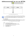
6.7. Battery temperature measurement.
Temperature measurement and compensation of the battery charging voltage can extend the life of the
batteries.
The PSU has a temperature sensor to monitor the temperature parameters of installed batteries. It is
recommended to place the temperature sensor between the batteries. Be careful not to damage the sensor
when moving the batteries.

www.pulsar.pl EN54M RED POWER plus
16
Fig. 12. Mounting of the temperature sensor.
The nominal battery operating temperature recommended by many manufacturers is
25°C. Working at elevated temperatures will significantly shorten the battery lifetime. The service
life is reduced by half for each sustained temperature rise of 8°C above the nominal temperature.
This means that the battery lifespan, when operated at 33°C, can be decreased by 50%!
6.8. Standby time.
Battery-assisted operating depends on battery capacity, charging level and load current. To maintain an
appropriate standby time, current drawn from the PSU in battery mode should be limited.
Required, minimum battery capacity to work with the PSU can be calculated with the following formula:
Q
AKU
= 1.25 ﴾ ﴾Id + Iz﴿ •Td + ﴾Ia + Iz﴿ •Ta + 0.05 Ic ﴿
where:
Q
AKU
– The minimum battery capacity [Ah]
1.25 – the factor related to the decrease in battery capacity due to aging
Id – the current drawn by the load during inspection [A]
Iz – PSU current consumption (including optional modules) [A] (Table 4)
Td – required inspection time [h]
Ia – the current drawn by the load during an alarm [A]
Ta – alarm duration [h]
Ic – short-term output current

www.pulsar.pl EN54M RED POWER plus
17
7. Technical parameters.
Electrical parameters (Table 4).
Mechanical parameters (Table 5).
Safety of use (Table 6).
Recommended types and sections of installation cables (Table 7).
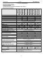
Table 4. Electrical parameters.
EN54M-2A7
EN54M-2A7-17
EN54M-3A7-17
EN54M-3A17-40
EN54M-5A7-17
EN54M-5A17-40
EN54M-5A40-65
EN54M-10A17-40
EN54M-10A40-65
Functional class EN 12101-10:2007
A
Mains supply
230 V
Current consumption
0,58 A
0,9 A
1,38 A
1,62 A
Inrush current
40 A
40 A
50 A
60 A
Power frequency
50 Hz
PSU’s power
56,8 W
85,2 W
142 W
284 W
Efficiency
88%
89%
87%
88%
Output voltage at 20 ºC
22 V÷ 27,6 V DC – buffer operation
20 V÷ 27,6 V DC – battery-assisted operation
Continuous output current Imax a
1,6 A
1,2 A
2,2 A
1,2 A
4,2 A
3,2 A
2,4 A
8,2 A
7,4 A
Instantaneous output current Imax b
(5 min)
2 A
3 A
5 A
10 A
Battery capacity
7,2 Ah
7÷20 Ah
7÷20 Ah
17÷45 Ah
7÷20 Ah
17÷45 Ah
40÷65 Ah
17÷45 Ah
40÷65 Ah
Battery charging current
0,4 A
0,8 A
0,8 A
1,8 A
0,8 A
1,8 A
2,6 A
1,8 A
2,6 A
Maximal resistance of the battery circuit
300mΩ
Ripple voltage (max.)
50mVp-p
50mVp-p
150mVp-p
30mVp-p
Current consumption by the PSU
during battery-assisted operation
52mA
52mA
55mA
85mA
Coefficient of temperature compensation
of the battery voltage
-36mV/ ºC (-5 ºC ÷ 40 ºC)
The LoB low battery voltage indication
Ubat < 23 V, during battery mode
Overvoltage protection OVP
U>32 V±2 V, automatic recovery
Short-circuit protection SCP
F4 A
F5 A
F6,3 A
F10 A
- F
AUX1
, F
AUX2
melting fuse (failure requires fuse replacement)
Overload protection OLP
105-150% of power supply, automatic recovery
Battery circuit protection SCP and reverse
polarity connection
F5 A
F6,3 A
F10 A
F12,5 A
- F
BAT
melting fuse (failure requires fuse replacement)
Deep discharge battery protection UVP
U<20 V (± 2%) – disconnection of the batteries
Technical outputs:
- EPS FLT; indicating AC power failure
- ALARM; indicating collective failure
- relay type: 1 A@ 30 V DC /50 V AC
- 10s time lag.
- relay type: 1 A@ 30 V DC /50 V AC
Technical inputs:
- EXTi; external failure input
- TAMPER; input of the microswitch
tamper
Closed input – no indication
Open input - alarm
Closed input – no indication
Open input - alarm
Optical indication:
- LEDs on the PCB of the power supply unit (see section 3.3)
Fuses: - F
BAT
- F
AUX1
- F
AUX2
F 5 A/250 V
F 4 A/250 V
F 4 A/250 V
F 6,3 A/250 V
F 5 A/250 V
F 5 A/250 V
F 10 A/250 V
F 6,3 A/250 V
F 6,3 A/250 V
F 12,5 A/250 V
F 10 A/250 V
F 10 A/250 V
Additional equipment
(not included)
- fuse modules: EN54C-LB4, EN54C-LB8
- sequential modules: EN54C-LS4, EN54C-LS8
- the EN54M-LED external optical indication panel
- bracket EN54M-DIN1

www.pulsar.pl EN54M RED POWER plus
18
Table 5. Mechanical parameters.
EN54M-2A7
EN54M- 2A7-17
EN54M- 3A7-17
EN54M- 3A17-40
EN54M- 5A7-17
EN54M- 5A17-40
EN54M- 5A40-65
EN54M- 10A17-40
EN54M- 10A40-65
Enclosure dimensions
(LxWxH)
200 x 120 x 48 [mm] [+/- 2mm]
204 x 141 x 52
[+/- 2mm]
237 x 168 x 55
[+/- 2mm]
Mounting (L1xW1)
(see Fig. 3)
212 x 75 x Φ5 [+/- 2mm]
216 x 88 x Φ5
[+/- 2mm]
249 x 84 x Φ5
[+/- 2mm]
Net/gross weight
0,95 kg
0,98 kg
1,48 kg
Terminals
Battery outputs BAT:
6,3F-2,5
Battery outputs BAT: Ф6 (M6-0-2,5)
Mains supply: Ф0,41÷2,59 (AWG 26-10), 0,5÷4mm
2
Outputs: Ф0,51÷2,05 (AWG 24-12), 0,5÷2,5mm
2
Notes
Convection cooling
Forced cooling
Table 6. Safety of use.
Protection class EN 60950-1:2007
I (first)
Protection grade EN 60529: 2003
IP00
Insulation electrical strength:
- between input (network) circuit and the output circuits of the PSU
- between input circuit and protection circuit
- between output circuit and protection circuit
3000 V AC min.
1500 V AC min.
500 V AC min.
Insulation resistance:
- between input circuit and output or protection circuit
100 MΩ, 500 V DC
Table 7. Recommended types and sections of installation cables.
Mains supply ~230 V L-N-PE (Table1 [1])
HDGs 3 x 0,75 mm
2
…1,5 mm
2
OMY 3 x 0,75 mm
2
…1,5 mm
2
AUX1, AUX2 output terminals (Table 1 [2])
HLGs 2 x 1,5 mm
2
…2,5 mm
2
Indication inputs/outputs (Table 1 [2])
YnTKSY 1 x 2 x 0,8 mm
2

www.pulsar.pl EN54M RED POWER plus
8. Technical inspections and maintenance.
Technical inspections and maintenance can be performed after disconnecting the power supply from
the power network. The PSU does not require any specific maintenance, however, its interior should be cleaned
with compressed air if it is used in dusty conditions. In case of fuse replacement, use only compatible
replacement parts.
Technical inspections should be carried out not less frequently than once per year. During the
inspection, check the batteries and run the battery test.
4 weeks after installation, re-tighten all threaded connections (Fig 2 [1,2]).
WEEE MARK
According to the EU WEE Directive – It is required not to dispose of electric or electronic
waste as unsorted municipal waste and to collect such WEEE separately.
CAUTION! The power supply unit is adapted for cooperation with the sealed lead-acid batteries (SLA). After the operation
period they must not be thrown but recycled according to the applicable law.
Pulsar sp.j.
Siedlec 150, 32-744 Łapczyca, Polska
Tel. (+48) 14-610-19-40, Fax. (+48) 14-610-19-50
e-mail: biuro@pulsar.pl, sales@pulsar.pl
http:// www.pulsar.pl, www.zasilacze.pl
-
 1
1
-
 2
2
-
 3
3
-
 4
4
-
 5
5
-
 6
6
-
 7
7
-
 8
8
-
 9
9
-
 10
10
-
 11
11
-
 12
12
-
 13
13
-
 14
14
-
 15
15
-
 16
16
-
 17
17
-
 18
18
-
 19
19


Ask a question and I''ll find the answer in the document
Finding information in a document is now easier with AI
Related papers
-
Pulsar EN54C-5A17LCD Operating instructions
-
-
-
-
-
-
-
-
Pulsar EN54-3A17 Operating instructions
-
