
Configuring Voice over IP for the Cisco 3600 Series VC-13
Configuring Voice over IP for the
Cisco 3600 Series
This chapter shows you how to configure Voice over IP (VoIP) on the Cisco 3600 series. For a
description of the commands used to configure Voice over IP, refer to the “Voice-Related
Commands” chapter in the Voice, Video, and Home Applications Command Reference.
VoIP enables a Cisco 3600 series router to carry voice traffic (for example, telephone calls and faxes)
over an IP network. Voice over IP is primarily a software feature; however, to use this feature on a
Cisco 3600 series router, you must install a voice network module (VNM). The VNM can hold either
two or four voice interface cards (VICs), each of which is specific to a particular signaling type
associated with a voice port. For more information about the physical characteristics, installing or
configuring a VNM in your Cisco 3600 series router, refer to the Voice Network Module and Voice
Interface Card Configuration Note that came with your VNM.
Voice over IP offers the following benefits:
• Toll bypass
• Remote PBX presence over WANs
• Unified voice/data trunking
• POTS-Internet telephony gateways
How Voice over IP Processes a Telephone Call
Before configuring Voice over IP on your Cisco 3600 series router, it helps to understand what
happens at an application level when you place a call using Voice over IP. The general flow of a
two-party voice call using Voice over IP is as follows:
1 The user picks up the handset; this signals an off-hook condition to the signaling application part
of Voice over IP in the Cisco 3600 series router.
2 The session application part of Voice over IP issues a dial tone and waits for the user to dial a
telephone number.
3 The user dials the telephone number; those numbers are accumulated and stored by the session
application.
4 After enough digits are accumulated to match a configured destination pattern, the telephone
number is mapped to an IP host via the dial plan mapper. The IP host has a direct connection to
either the destination telephone number or a PBX that is responsible for completing the call to
the configured destination pattern.

List of Terms
VC-14
Voice, Video, and Home Applications Configuration Guide
5 The session application then runs the H.323 session protocol to establish a transmission and a
reception channel for each direction over the IP network. If the call is being handled by a PBX,
the PBX forwards the call to the destination telephone. If RSVP has been configured, the RSVP
reservations are put into effect to achieve the desired quality of service over the IP network.
6 The CODECs are enabled for both ends of the connection and the conversation proceeds using
RTP/UDP/IP as the protocol stack.
7 Any call-progress indications (or other signals that can be carried in-band) are cut through the
voice path as soon as end-to-end audio channel is established. Signaling that can be detected by
the voice ports (for example, in-band DTMF digits after the call setup is complete) is also trapped
by the session application at either end of the connection and carried over the IP network
encapsulated in RTCP using the RTCP APP extension mechanism.
8 When either end of the call hangs up, the RSVP reservations are torn down (if RSVP is used) and
the session ends. Each end becomes idle, waiting for the next off-hook condition to trigger
another call setup.
List of Terms
ACOM—Term used in G.165, “General Characteristics of International Telephone Connections and
International Telephone Circuits: Echo Cancellers.” ACOM is the combined loss achieved by the
echo canceller, which is the sum of the Echo Return Loss, Echo Return Loss Enhancement, and
nonlinear processing loss for the call.
Call leg—A logical connection between the router and either a telephony endpoint over a bearer
channel or another endpoint using a session protocol.
CIR—Committed information Rate. The average rate of information transfer a subscriber (for
example, the network administrator) has stipulated for a Frame Relay PVC.
CODEC—coder-decoder. Device that typically uses pulse code modulation to transform analog
signals into a digital bit stream and digital signals back into analog signals. In Voice over IP, it
specifies the voice coder rate of speech for a dial peer.
Dial peer—An addressable call endpoint. In Voice over IP, there are two kinds of dial peers: POTS
and VoIP.
DTMF—Dual tone multifrequency. Use of two simultaneous voice-band tones for dial (such as
touch tone).
E&M—E&M stands for recEive and transMit (or Ear and Mouth). E&M is a trunking arrangement
generally used for two-way switch-to-switch or switch-to-network connections. Cisco’s E&M
interface is an RJ-48 connector that allows connections to PBX trunk lines (tie lines).
FIFO—First-in, first-out. In data communication, FIFO refers to a buffering scheme where the first
byte of data entering the buffer is the first byte retrieved by the CPU. In telephony, FIFO refers to a
queuing scheme where the first calls received are the first calls processed.
FXO—Foreign Exchange Office. An FXO interface connects to the PSTN’s central office and is the
interface offered on a standard telephone. Cisco’s FXO interface is an RJ-11 connector that allows
an analog connection to be directed at the PSTN’s central office. This interface is of value for
off-premise extension applications.
FXS—Foreign Exchange Station. An FXS interface connects directly to a standard telephone and
supplies ring, voltage, and dial tone. Cisco’s FXS interface is an RJ-11 connector that allows
connections to basic telephone service equipment, keysets, and PBXs.
Multilink PPP—Multilink Point-to-Point Protocol. This protocol is a method of splitting,
recombining, and sequencing datagrams across multiple logical data links.

Prerequisite Tasks
Configuring Voice over IP for the Cisco 3600 Series VC-15
PBX—Private Branch Exchange. Privately-owned central switching office.
PLAR—Private Line Auto Ringdown. This type of service results in a call attempt to some
particular remote endpoint when the local extension is taken off-key.
POTS—Plain Old Telephone Service. Basic telephone service supplying standard single line
telephones, telephone lines, and access to the public switched telephone network.
POTS dial peer—Dial peer connected via a traditional telephony network. POTS peers point to a
particular voice port on a voice network device.
PSTN—Public Switched Telephone Network. PSTN refers to the local telephone company.
PVC—Permanent virtual circuit.
QoS—Quality of Service. QoS refers to the measure of service quality provided to the user.
RSVP—Resource Reservation Protocol. This protocol supports the reservation of resources across
an IP network.
Trunk—Service that allows quasi-transparent connections between two PBXs, a PBX and a local
extension, or some other combination of telephony interfaces to be permanently conferenced
together by the session application and signaling passed transparently through the IP network.
VoIP dial peer—Dial peer connected via a packet network; in the case of Voice over IP, this is an
IP network. VoIP peers point to specific VoIP devices.
Prerequisite Tasks
Before you can configure your Cisco 3600 series router to use Voice over IP, you must first:
• Establish a working IP network. For more information about configuring IP, refer to the
“IP Overview,” “Configuring IP Addressing,” and “Configuring IP Services” chapters in the
Network Protocols Configuration Guide, Part 1.
• Install the one-slot or two-slot (NM-1V/NM-2V) voice network module into the appropriate bay
of your Cisco router. For more information about the physical characteristics of the voice network
module, or how to install it, refer to the installation documentation, Voice Network Module and
Voice Interface Card Configuration Note, that came with your voice network module.
• Complete your company’s dial plan.
• Establish a working telephony network based on your company’s dial plan.
• Integrate your dial plan and telephony network into your existing IP network topology. Merging
your IP and telephony networks depends on your particular IP and telephony network topology.
In general, we recommend the following suggestions:
— Use canonical numbers wherever possible. It is important to avoid situations where
numbering systems are significantly different on different routers or access servers in your
network.
— Make routing and/or dialing transparent to the user—for example, avoid secondary dial tones
from secondary switches, where possible.
— Contact your PBX vendor for instructions about how to reconfigure the appropriate PBX
interfaces.
After you have analyzed your dial plan and decided how to integrate it into your existing IP network,
you are ready to configure your network devices to support Voice over IP.

Voice over IP Configuration Task List
VC-16
Voice, Video, and Home Applications Configuration Guide
Voice over IP Configuration Task List
To configure Voice over IP on the Cisco 3600 series, you need to complete the following tasks:
1 Configure IP Networks for Real-Time Voice Traffic
Configure your IP network to support real-time voice traffic. Fine-tuning your network to
adequately support VoIP involves a series of protocols and features geared toward Quality of
Service (QoS). To configure your IP network for real-time voice traffic, you need to take into
consideration the entire scope of your network, then select and configure the appropriate QoS
tool or tools:
(a) Multilink PPP with Interleaving
(b) RTP Header Compression
(c) Custom Queuing
(d) Weighted Fair Queuing
Refer to “Configure IP Networks for Real-Time Voice Traffic” section for information about how
to select and configure the appropriate QoS tools to optimize voice traffic on your network.
2 Configure Frame Relay for Voice over IP
(Optional) If you plan to run Voice over IP over Frame Relay, you need to take certain factors
into consideration when configuring Voice over IP for it to run smoothly over Frame Relay. For
example, a public Frame Relay cloud provides no guarantees for QoS. Refer to the “Configure
Frame Relay for Voice over IP” section for information about deploying Voice over IP over
Frame Relay.
3 Configure Number Expansion
Use the num-exp command to configure number expansion if your telephone network is
configured so that you can reach a destination by dialing only a portion (an extension number) of
the full E.164 telephone number. Refer to the “Configure Number Expansion” section for
information about number expansion.
4 Configure Dial Peers
Use the dial-peer voice command to define dial peers and switch to the dial-peer configuration
mode. Each dial peer defines the characteristics associated with a call leg. A call leg is a discrete
segment of a call connection that lies between two points in the connection. An end-to-end call
is comprised of four call legs, two from the perspective of the source access server, and two from
the perspective of the destination access server. Dial peers are used to apply attributes to call legs
and to identify call origin and destination. There are two different kinds of dial peers:
(a) POTS—Dial peer describing the characteristics of a traditional telephony network
connection. POTS peers point to a particular voice port on a voice network device. To
minimally configure a POTS dial peer, you need to configure the following two
characteristics: associated telephone number and logical interface. Use the
destination-pattern command to associate a telephone number with a POTS peer. Use the
port command to associate a specific logical interface with a POTS peers. In addition, you
can specify direct inward dialing for a POTS peer by using the direct-inward-dial
command.

Configure IP Networks for Real-Time Voice Traffic
Configuring Voice over IP for the Cisco 3600 Series VC-17
(b) VoIP—Dial peer describing the characteristics of a packet network connection; in the case
of Voice over IP, this is an IP network. VoIP peers point to specific VoIP devices. To
minimally configure a VoIP peer, you need to configure the following two characteristics:
associated destination telephone number and a destination IP address. Use the
destination-pattern command to define the destination telephone number associated with
a VoIP peer. Use the session target command to specify a destination IP address for a VoIP
peer.
Refer to the “Configure Dial Peers” section additional information about configuring dial peers
and dial-peer characteristics.
5 Optimize Dial Peer and Network Interface Configurations
You can use VoIP peers to define characteristics such as IP precedence, additional QoS
parameters (when RSVP is configured), CODEC, and VAD. Use the ip precedence command to
define IP precedence. If you have configured RSVP, use either the req-qos or acc-qos command
to configure QoS parameters. Use the codec command to configure specific voice coder rates.
Use the vad command to disable voice activation detection and the transmission of silence
packets. Refer to the “Optimize Dial Peer and Network Interface Configurations” section for
additional information about optimizing dial-peer characteristics.
6 Configure Voice Ports
You need to configure your Cisco 3600 series router to support voice ports. In general, voice-port
commands define the characteristics associated with a particular voice-port signaling type. voice
ports on the Cisco 3600 series support three basic voice signaling types:
(a) FXO—Foreign Exchange Office interface
(b) FXS—The Foreign Exchange Station interface
(c) E&M—The “Ear and Mouth” interface (or “RecEive and TransMit” interface)
Under most circumstances, the default voice-port command values are adequate to configure
FXO and FXS ports to transport voice data over your existing IP network. Because of the inherent
complexities involved with PBX networks, E&M ports might need specific voice-port values
configured, depending on the specifications of the devices in your telephony network. For
information about configuring voice ports, refer to the “Configuring Voice Ports” chapter.
7 Configure Voice over IP for Microsoft NetMeeting
(Optional) Voice over IP can be used with Microsoft NetMeeting (Version 2.x) when the
Cisco 3600 series router is used as the voice gateway. Refer to the 'Configure Voice over IP for
Microsoft NetMeeting” section for more information about configuring Voice over IP to support
Microsoft NetMeeting.
Configure IP Networks for Real-Time Voice Traffic
You need to have a well-engineered network end-to-end when running delay-sensitive applications
such as VoIP. Fine-tuning your network to adequately support VoIP involves a series of protocols and
features geared toward Quality of Service (QoS). It is beyond the scope of this document to explain
the specific details relating to wide-scale QoS deployment. Cisco IOS software provides many tools
for enabling QoS on your backbone, such as Random Early Detection (RED), Weighted Random
Early Detection (WRED), Fancy queuing (meaning custom, priority, or weighted fair queuing), and
IP Precedence. To configure your IP network for real-time voice traffic, you need to take into
consideration the entire scope of your network, then select the appropriate QoS tool or tools.

Configure IP Networks for Real-Time Voice Traffic
VC-18
Voice, Video, and Home Applications Configuration Guide
The important thing to remember is that QoS must be configured throughout your network—not just
on the Cisco 3600 series devices running VoIP—to improve voice network performance. Not all QoS
techniques are appropriate for all network routers. Edge routers and backbone routers in your
network do not necessarily perform the same operations; the QoS tasks they perform might differ as
well. To configure your IP network for real-time voice traffic, you need to take into consideration
the functions of both edge and backbone routers in your network, then select the appropriate QoS
tool or tools.
In general, edge routers perform the following QoS functions:
• Packet classification
• Admission control
• Bandwidth management
• Queuing
In general, backbone routers perform the following QoS functions:
• High-speed switching and transport
• Congestion management
• Queue management
Scalable QoS solutions require cooperative edge and backbone functions.
Note In a subsequent Cisco IOS release, we have implemented enhancements to improve QoS on
low speed, wide-area links, such as ISDN, MLPPP, and Frame Relay running on edge routers. For
more information about these enhancements, refer to the Cisco IOS Release 12.0(5)T “IP RTP”
feature module.
Although not mandatory, some QoS tools have been identified as being valuable in fine-tuning your
network to support real-time voice traffic. To configure your IP network for QoS using these tools,
perform one or more of the following tasks:
• Configure Multilink PPP with Interleaving
• Configure RTP Header Compression
• Configure Custom Queuing
• Configure Weighted Fair Queuing
Each of these components is discussed in the following sections.

Configure Multilink PPP with Interleaving
Configuring Voice over IP for the Cisco 3600 Series VC-19
Configure Multilink PPP with Interleaving
Multi-class Multilink PPP Interleaving allows large packets to be multilink-encapsulated and
fragmented into smaller packets to satisfy the delay requirements of real-time voice traffic; small
real-time packets, which are not multilink-encapsulated, are transmitted between fragments of the
large packets. The interleaving feature also provides a special transmit queue for the smaller,
delay-sensitive packets, enabling them to be transmitted earlier than other flows. Interleaving
provides the delay bounds for delay-sensitive voice packets on a slow link that is used for other
best-effort traffic.
Note Interleaving applies only to interfaces that can configure a multilink bundle interface. These
include virtual templates, dialer interfaces, and Integrated Services Digital Network (ISDN) Basic
Rate Interface (BRI) or Primary Rate Interface (PRI) interfaces.
In general, Multilink PPP with interleaving is used in conjunction with weighted fair queuing and
RSVP or IP Precedence to ensure voice packet delivery. Use Multilink PPP with interleaving and
weighted fair queuing to define how data will be managed; use RSVP or IP Precedence to give
priority to voice packets.
You should configure Multilink PPP if the following conditions exist in your network:
• Point-to-point connection using PPP Encapsulation
• Slow links
Note Multilink PPP should not be used on links greater than 2 Mbps.
Multilink PPP support for interleaving can be configured on virtual templates, dialer interfaces, and
ISDN BRI or PRI interfaces. To configure interleaving, you need to complete the following tasks:
• Configure the dialer interface or virtual template, as defined in the relevant chapters of the
Dial Solutions Configuration Guide.
• Configure Multilink PPP and interleaving on the interface or template.
To configure Multilink PPP and interleaving on a configured and operational interface or virtual
interface template, use the following commands in interface mode:
Note The ip rtp reserve command can be used instead of configuring RSVP. If you configure
RSVP, this command is not required.
Step Command Purpose
1 ppp multilink Enable Multilink PPP.
2 ppp multilink interleave Enable real-time packet interleaving.
3 ppp multilink fragment-delay milliseconds Optionally, configure a maximum fragment delay.
4 ip rtp reserve lowest-UDP-port
range-of-ports [maximum-bandwidth]
Reserve a special queue for real-time packet flows
to specified destination User Datagram Protocol
(UDP) ports, allowing real-time traffic to have
higher priority than other flows. This is only
applicable if you have not configured RSVP.

Configure IP Networks for Real-Time Voice Traffic
VC-20
Voice, Video, and Home Applications Configuration Guide
For more information about Multilink PPP, refer to the “Configuring Media-Independent PPP and
Multilink PPP” chapter in the Dial Solutions Configuration Guide.
Multilink PPP Configuration Example
The following example defines a virtual interface template that enables Multilink PPP with
interleaving and a maximum real-time traffic delay of 20 milliseconds, and then applies that virtual
template to the Multilink PPP bundle:
interface virtual-template 1
ppp multilink
encapsulated ppp
ppp multilink interleave
ppp multilink fragment-delay 20
ip rtp reserve 16384 100 64
multilink virtual-template 1
Configure RTP Header Compression
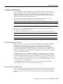
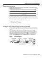
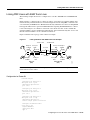
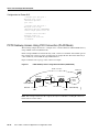
Real-Time Transport Protocol (RTP) is used for carrying packetized audio traffic over an IP network.
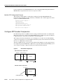
RTP header compression compresses the IP/UDP/RTP header in an RTP data packet from 40 bytes
to approximately 2 to 4 bytes (most of the time), as shown in Figure 4.
This compression feature is beneficial if you are running Voice over IP over slow links. Enabling
compression on both ends of a low-bandwidth serial link can greatly reduce the network overhead if
there is a lot of RTP traffic on that slow link.
Typically, an RTP packet has a payload of approximately 20 to 160 bytes for audio applications that
use compressed payloads. RTP header compression is especially beneficial when the RTP payload
size is small (for example, compressed audio payloads between 20 and 50 bytes).
Figure 4 RTP Header Compression
Before RTP header compression:
20 bytes 8 bytes
20 to 160 bytes
12 bytes
IP
Header
UDP
RTP Payload
After RTP header compression:
2 to 4 bytes
20 to 160 bytes
IP/UDP/RTP header
Payload
12076

Configure RTP Header Compression
Configuring Voice over IP for the Cisco 3600 Series VC-21
You should configure RTP header compression if the following conditions exist in your network:
• Slow links
• Need to save bandwidth
Note RTP header compression should not be used on links greater than 2 Mbps.
Perform the following tasks to configure RTP header compression for Voice over IP. The first task is
required; the second task is optional.
• Enable RTP Header Compression on a Serial Interface
• Change the Number of Header Compression Connections
Enable RTP Header Compression on a Serial Interface
To use RTP header compression, you need to enable compression on both ends of a serial
connection. To enable RTP header compression, use the following command in interface
configuration mode:
If you include the passive keyword, the software compresses outgoing RTP packets only if incoming
RTP packets on the same interface are compressed. If you use the command without the passive
keyword, the software compresses all RTP traffic.
Change the Number of Header Compression Connections
By default, the software supports a total of 16 RTP header compression connections on an interface.
To specify a different number of RTP header compression connections, use the following command
in interface configuration mode:
RTP Header Compression Configuration Example
The following example enables RTP header compression for a serial interface:
interface 0
ip rtp header-compression
encapsulation ppp
ip rtp compression-connections 25
For more information about RTP header compression, see the “Configuring IP Multicast Routing”
chapter of the Network Protocols Configuration Guide, Part 1.
Command Purpose
ip rtp header-compression [passive] Enable RTP header compression.
Command Purpose
ip rtp compression connections number Specify the total number of RTP header
compression connections supported on an interface.

Configure Frame Relay for Voice over IP
VC-22
Voice, Video, and Home Applications Configuration Guide
Configure Custom Queuing
Some QoS features, such as IP RTP reserve and custom queuing, are based on the transport protocol
and the associated port number. Real-time voice traffic is carried on UDP ports ranging from 16384
to 16624. This number is derived from the following formula:
16384 = 4(number of voice ports in the Cisco 3600 series router)
Custom Queuing and other methods for identifying high priority streams should be configured for
these port ranges. For more information about custom queuing, refer to the “Performing Basic
System Management” chapter in the Configuration Fundamentals Configuration Guide.
Configure Weighted Fair Queuing
Weighted fair queuing ensures that queues do not starve for bandwidth and that traffic gets
predictable service. Low-volume traffic streams receive preferential service; high-volume traffic
streams share the remaining capacity, obtaining equal or proportional bandwidth.
In general, weighted fair queuing is used in conjunction with Multilink PPP with interleaving and
RSVP or IP Precedence to ensure that voice packet delivery. Use weighted fair queuing with
Multilink PPP to define how data will be managed; use RSVP or IP Precedence to give priority to
voice packets. For more information about weighted fair queuing, refer to the “Performing Basic
System Management” chapter in the Configuration Fundamentals Configuration Guide.
Configure Frame Relay for Voice over IP
You need to take certain factors into consideration when configuring Voice over IP for it to run
smoothly over Frame Relay. A public Frame Relay cloud provides no guarantees for QoS. For
real-time traffic to be transmitted in a timely manner, the data rate must not exceed the committed
information rate (CIR) or there is the possibility that packets will be dropped. In addition, Frame
Relay traffic shaping and RSVP are mutually exclusive. This is particularly important to remember
if multiple DLCIs are carried on a single interface.
For Frame Relay links with slow output rates (less than or equal to 64 kbps) where data and voice
are being transmitted over the same PVC, we recommend the following solutions:
• Separate DLCIs for voice and data—By providing a separate subinterface for voice and data, you
can use the appropriate QoS tool per line. For example, each DLCI would use 32 kbps of a
64 kbps line.
— Apply adaptive traffic shaping to both DLCIs.
— Use RSVP or IP Precedence to prioritize voice traffic.
— Use compressed RTP to minimize voice packet size.
— Use weighted fair queuing to manage voice traffic.
• Lower MTU size—Voice packets are generally small. By lowering the MTU size (for example,
to 300 bytes), large data packets can be broken up into smaller data packets that can more easily
be interwoven with voice packets.
Note Some applications do not support a smaller MTU size. If you decide to lower MTU size,
use the ip mtu command; this command affects only IP traffic.

Frame Relay for Voice over IP Configuration Example
Configuring Voice over IP for the Cisco 3600 Series VC-23
Note Lowering the MTU size affects data throughput speed.
• CIR equal to line rate—Make sure that the data rate does not exceed the CIR. This is
accomplished through generic traffic shaping.
— Use IP Precedence to prioritize voice traffic.
— Use compressed RTP to minimize voice packet header size.
• Traffic shaping—Use adaptive traffic shaping to throttle back the output rate based on the BECN.
If the feedback from the switch is ignored, packets (both data and voice) might be discarded.
Because the Frame Relay switch does not distinguish between voice and data packets, voice
packets could be discarded, which would result in a deterioration of voice quality.
— Use compressed RTP, reduced MTU size, and adaptive traffic shaping based on BECN to
hold data rate to CIR.
— Use generic traffic shaping to obtain a low interpacket wait time. For example, set Bc to 4000
to obtain an inter-packet wait of 125 ms.
Note We recommend FRF.12 fragmentation setup rules for Voice over IP connections over Frame
Relay. FRF.12 was implemented in the Cisco IOS Release 12.0(4)T. For more information, refer to
the Cisco IOS Release 12.0(4)T “Voice over Frame Relay using FRF.11 and FRF.12” feature
module.
Frame Relay for Voice over IP Configuration Example
For Frame Relay, it is customary to configure a main interface and several subinterfaces, one
subinterface per PVC. The following example configures a Frame Relay main interface and a
subinterface so that voice and data traffic can be successfully transported:
interface Serial0/0
ip mtu 300
no ip address
encapsulation frame-relay
no ip route-cache
no ip mroute-cache
fair-queue 64 256 1000
frame-relay ip rtp header-compression
interface Serial0/0.1 point-to-point
ip mtu 300
ip address 40.0.0.7 255.0.0.0
no ip route-cache
no ip mroute-cache
bandwidth 64
traffic-shape rate 32000 4000 4000
frame-relay interface-dlci 16
frame-relay ip rtp header-compression
In this configuration example, the main interface has been configured as follows:
• MTU size of IP packets is 300 bytes.
• No IP address is associated with this serial interface. The IP address must be assigned for the
subinterface.
• Encapsulation method is Frame Relay.

Configure Number Expansion
VC-24
Voice, Video, and Home Applications Configuration Guide
• Fair-queuing is enabled.
• IP RTP header compression is enabled.
The subinterface has been configured as follows:
• MTU size is inherited from the main interface.
• IP address for the subinterface is specified.
• Bandwidth is set to 64 kbps.
• Generic traffic shaping is enabled with 32 kbps CIR where Bc=4000 bits and Be=4000 bits.
• Frame Relay DLCI number is specified.
• IP RTP header compression is enabled.
Note When traffic bursts over the CIR, output rate is held at the speed configured for the CIR (for
example, traffic will not go beyond 32 kbps if CIR is set to 32 kbps).
For more information about Frame Relay, refer to the “Configuring Frame Relay” chapter in the
Wide-Area Networking Configuration Guide.
Configure Number Expansion
In most corporate environments, the telephone network is configured so that you can reach a
destination by dialing only a portion (an extension number) of the full E.164 telephone number.
Voice over IP can be configured to recognize extension numbers and expand them into their full
E.164 dialed number by using two commands in tandem: destination-pattern and num-exp. Before
you configure these two commands, it is helpful to map individual telephone extensions with their
full E.164 dialed numbers. This task can be done easily by creating a number expansion table.
Create a Number Expansion Table
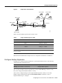
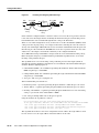
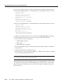
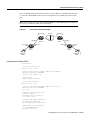
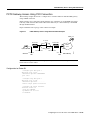
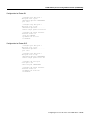
In Figure 5, a small company wants to use Voice over IP to integrate its telephony network with its
existing IP network. The destination pattern (or expanded telephone number) associated with
Router 1 (located to the left of the IP cloud) are (408) 115-xxxx, (408) 116-xxxx, and
(408) 117-xxxx, where xxxx identifies the individual dial peers by extension. The destination pattern
(or expanded telephone number) associated with Router 2 (located to the right of the IP cloud) is
(729) 555-xxxx.

Configure Number Expansion
Configuring Voice over IP for the Cisco 3600 Series VC-25
Figure 5 Sample Voice over IP Network
Table 5 shows the number expansion table for this scenario.
Table 5 Sample Number Expansion Table
Note You can use the period symbol (.) to represent variables (such as extension numbers) in a
telephone number.
The information included in this example needs to be configured on both Router 1 and Router 2.
Configure Number Expansion
To define how to expand an extension number into a particular destination pattern, use the following
command in global configuration mode:
You can verify the number expansion information by using the show num-exp command to verify
that you have mapped the telephone numbers correctly.
After you have configured dial peers and assigned destination patterns to them, you can verify
number expansion information by using the show dialplan number command to see how a
telephone number maps to a dial peer.
Extension Destination Pattern Num-Exp Command Entry
5.... 40811..... num-exp 5.... 408115....
6.... 40811..... num-exp 6.... 408116....
7.... 40811..... num-exp 7.... 408117....
1... 729555.... num-exp 2.... 729555....
Command Purpose
num-exp
extension-number extension-string Configure number expansion.
408 116-1002
408 115-1001
408 117-1003
729 555-1000 729 555-1003
729 555-1001 729 555-1002
Cisco 3600
Router 1
WAN
WAN
T1 ISDN PRI
T1
ISDN PRI
10.1.1.1
10.1.1.2
IP
cloud
Cisco 3600
Router 2
Voice port 0:D
Voice port
0:D
15586
1:D

Configure Dial Peers
VC-26
Voice, Video, and Home Applications Configuration Guide
Configure Dial Peers
The key point to understanding how Voice over IP functions is to understand dial peers. Each dial
peer defines the characteristics associated with a call leg, as shown in Figure 6 and Figure 7. A call
leg is a discrete segment of a call connection that lies between two points in the connection. All the
call legs for a particular connection have the same connection ID.
There are two different kinds of dial peers:
• POTS—Dial peer describing the characteristics of a traditional telephony network connection.
POTS peers point to a particular voice port on a voice network device.
• VoIP—Dial peer describing the characteristics of a packet network connection; in the case of
Voice over IP, this is an IP network. VoIP peers point to specific VoIP devices.
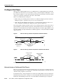
Four call legs make comprise and end-to-end call—two from the perspective of the source router as
shown in Figure 6, and two from the perspective of the destination router as shown in Figure 7. A
dial peer is associated with each one of these call legs. Dial peers are used to apply attributes to call
legs and to identify call origin and destination. Attributes applied to a call leg include QoS, CODEC,
VAD, and fax rate.
Figure 6 Dial Peer Call Legs from the Perspective of the Source Router
Figure 7 Dial Peer Call Legs from the Perspective of the Destination Router
Inbound versus Outbound Dial Peers
Dial peers are used for both inbound and outbound call legs. It is important to remember that these
terms are defined from the router’s perspective. An inbound call leg originates outside the router. An
outbound call leg originates from the router.
For inbound call legs, a dial peer might be associated to the calling number or the port designation.
Outbound call legs always have a dial peer associated with them. The destination pattern is used to
identify the outbound dial peer. The call is associated with the outbound dial peer at setup time.
10353
IP cloud
Destination
Source
Call leg for POTS
dial peer 1
Source router
Call leg for VoIP
dial peer 2
10354
IP cloud
Destination router
Call leg for POTS
dial peer 4
Call leg for VoIP
dial peer 3
Destination
Source

Inbound versus Outbound Dial Peers
Configuring Voice over IP for the Cisco 3600 Series VC-27
POTS peers associate a telephone number with a particular voice port so that incoming calls for that
telephone number can be received and outgoing calls can be placed. VoIP peers point to specific
devices (by associating destination telephone numbers with a specific IP address) so that incoming
calls can be received and outgoing calls can be placed. Both POTS and VoIP peers are needed to
establish Voice over IP connections.
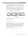
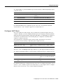
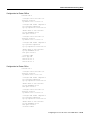
Establishing communication using Voice over IP is similar to configuring an IP static route: you are
establishing a specific voice connection between two defined endpoints. As shown in Figure 8, for
outgoing calls (from the perspective of the POTS dial peer 1), the POTS dial peer establishes the
source (via the originating telephone number or voice port) of the call. The VoIP dial peer establishes
the destination by associating the destination phone number with a specific IP address.
Figure 8 Outgoing Calls from the Perspective of POTS Dial Peer 1
To configure call connectivity between the source and destination as illustrated in Figure 8, enter the
following commands on router 10.1.2.2:
dial-peer voice 1 pots
destination-pattern 1408555....
port 1/0/0
dial-peer voice 2 voip
destination-pattern 1310555....
session target ipv4:10.1.1.2
In the previous configuration example, the last four digits in the VoIP dial peer’s destination pattern
were replaced with wildcards. This means that from access server 10.1.2.2, calling any number string
that begins with the digits “1310555” will result in a connection to access server 10.1.1.2. This
implies that access server 10.1.1.2 services all numbers beginning with those digits. From access
server 10.1.1.2, calling any number string that begins with the digits “1408555” will result in a
connection to access server 10.1.2.2. This implies that access server 10.1.2.2 services all numbers
beginning with those digits. For more information about stripping and adding digits, see the
“Outbound Dialing on POTS Peers” section.
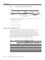
Figure 9 shows how to complete the end-to-end call between dial peer 1 and dial peer 4.
S6613
(408) 555-4000
(310) 555-1000
10.1.2.2
Source Destination
10.1.1.2
Voice port
1/0/0
Voice port
1/0/0
IP cloud
Dial peer 1
Dial peer 2 Dial peer 3
VoIP call leg
POTS call leg
Dial peer 4

Configure Dial Peers
VC-28
Voice, Video, and Home Applications Configuration Guide
Figure 9 Outgoing Calls from the Perspective of POTS Dial Peer 2
To complete the end-to-end call between dial peer 1 and dial peer 4 as illustrated in Figure 9, enter
the following commands on router 10.1.1.2:
dial-peer voice 4 pots
destination-pattern 1310555....
port 1/0/0
dial-peer voice 3 voip
destination-pattern 1408555....
session target ipv4:10.1.2.2
Create a Peer Configuration Table
There is specific data relative to each dial peer that needs to be identified before you can configure
dial peers in Voice over IP. One way to do this is to create a peer configuration table.
Using the example in Figure 5, Router 1, with an IP address of 10.1.1.1, connects a small sales
branch office to the main office through Router 2. There are three telephones in the sales branch
office that need to be established as dial peers. Router 2, with an IP address of 10.1.1.2, is the primary
gateway to the main office; as such, it needs to be connected to the company’s PBX. There are four
devices that need to be established as dial peers in the main office, all of which are basic telephones
connected to the PBX. Figure 5 shows a diagram of this small voice network.
Table 6 shows the peer configuration table for the example illustrated in Figure 5.
Table 6 Peer Configuration Table for Sample Voice Over IP Network
Commands
Dial Peer
Tag Ext Dest-Pattern Type Voice Port session target CODEC QoS
Router 1
1 6.... +1408116.... POTS
10 +1729555.... VoIP IPV4 10.1.1.2 G.729 Best Effort
Router 2
11 +1408116.... VoIP IPV4 10.1.1.1 G.729 Best Effort
4 2.... +1729555.... POTS
S6614
(408) 555-4000
Dial peer 1
Dial peer 2
Dial peer 3
VoIP call leg
POTS call leg
Dial peer 4
(310) 555-1000
10.1.2.2
SourceDestination
10.1.1.2
Voice port
1/0/0
Voice port
1/0/0
IP cloud

Configure POTS Peers
Configuring Voice over IP for the Cisco 3600 Series VC-29
Configure POTS Peers
Once again, POTS peers enable incoming calls to be received by a particular telephony device. To
configure a POTS peer, you need to uniquely identify the peer (by assigning it a unique tag number),
define its telephone number(s), and associate it with a voice port through which calls will be
established. Under most circumstances, the default values for the remaining dial-peer configuration
commands will be sufficient to establish connections.
To enter the dial-peer configuration mode (and select POTS as the method of voice-related
encapsulation), use the following command in global configuration mode:
The number value of the dial-peer voice pots command is a tag that uniquely identifies the dial peer.
(This number has local significance only.)
To configure the identified POTS peer, use the following commands in dial-peer configuration mode:
Outbound Dialing on POTS Peers
When a router receives a voice call, it selects an outbound dial peer by comparing the called number
(the full E.164 telephone number) in the call information with the number configured as the
destination pattern for the POTS peer. The router then strips out the left-justified numbers
corresponding to the destination pattern matching the called number. If you have configured a prefix,
the prefix will be put in front of the remaining numbers, creating a dial string, which the router will
then dial. If all numbers in the destination pattern are stripped-out, the user will receive (depending
on the attached equipment) a dial tone.
For example, suppose there is a voice call whose E.164 called number is 1(310) 555-2222. If you
configure a destination-pattern of “1310555” and a prefix of “9,” the router will strip out “1310555”
from the E.164 telephone number, leaving the extension number of “2222.” It will then append the
prefix, “9,” to the front of the remaining numbers, so that the actual numbers dialed is “9, 2222.” The
comma in this example means that the router will pause for one second between dialing the “9” and
the “2” to allow for a secondary dial tone.
For additional POTS dial-peer configuration options, refer to the “Voice-Related Commands”
section of the Voice, Video, and Home Applications Command Reference.
Direct Inward Dial for POTS Peers
Direct inward dial (DID) is used to determine how the called number is treated for incoming POTS
call legs. As shown in Figure 10, incoming means from the perspective of the router. In this case, it
is the call leg coming into the access server to be forwarded through to the appropriate destination
pattern.
Command Purpose
dial-peer voice number pots Enter the dial-peer configuration mode to configure a POTS
peer.
Step Command Purpose
1 destination-pattern string Define the telephone number associated with this POTS dial
peer.
2 port slot-number/subunit-number/port Associate this POTS dial peer with a specific voice port.

Configure Dial Peers
VC-30
Voice, Video, and Home Applications Configuration Guide
Figure 10 Incoming and Outgoing POTS Call Legs
Unless otherwise configured, when a call arrives on the access server, the server presents a dial tone
to the caller and collects digits until it can identify the destination dial peer. After the dial peer has
been identified, the call is forwarded through the next call leg to the destination.
There are cases where it might be necessary for the server to use the called-number (DNIS) to find
a dial peer for the outgoing call leg—for example, if the switch connecting the call to the server has
already collected the digits. DID enables the server to match the called-number with a dial peer and
then directly place the outbound call. With DID, the server does not present a dial tone to the caller
and does not collect digits; it forwards the call directly to the configured destination.
To use DID and incoming called-number, a dial peer must be associated with the incoming call leg.
Before doing this, it helps if you understand the logic behind the algorithm used to associate the
incoming call leg with the dial peer.
The algorithm used to associate incoming call legs with dial peers uses three inputs (which are
derived from signaling and interface information associated with the call) and four defined dial-peer
elements. The three signaling inputs are:
• Called-number (DNIS)—Set of numbers representing the destination, which is derived from the
ISDN setup message or CAS DNIS.
• Calling-number (ANI)—Set of numbers representing the origin, which is derived from the ISDN
setup message or CAS DNIS.
• Voice port—The voice port carrying the call.
The four defined dial-peer elements are:
• Destination pattern—A pattern representing the phone numbers to which the peer can connect.
• Answer address—A pattern representing the phone numbers from which the peer can connect.
• Incoming called-number—A pattern representing the phone numbers that associate an incoming
call leg to a peer based on the called-number or DNIS.
• Port—The port through which calls to this peer are placed.
Using the elements, the algorithm is as follows:
For all peers where call type (VoIP versus POTS) match dial-peer type:
if the type is matched, associate the called number with the incoming called-number
else if the type is matched, associate calling-number with answer-address
else if the type is matched, associate calling-number with destination-pattern
else if the type is matched, associate voice port to port
This algorithm shows that if a value is not configured for answer-address, the origin address is used
because, in most cases, the origin address and answer-address are the same.
PBX
Cisco 3600
Incoming
call leg
Outgoing
call le
g
Cisco 3600
PBX
15564
IP
cloud

Configure VoIP Peers
Configuring Voice over IP for the Cisco 3600 Series VC-31
To configure DID for a particular POTS dial peer, use the following commands beginning in global
configuration mode:
Note Direct inward dial is configured for the calling POTS dial peer.
For additional POTS dial-peer configuration options, refer to the “Voice-Related Commands”
section of the Voice, Video, and Home Applications Command Reference.
Configure VoIP Peers
Once again, VoIP peers enable outgoing calls to be made from a particular telephony device. To
configure a VoIP peer, you need to uniquely identify the peer (by assigning it a unique tag number),
define its destination telephone number and destination IP address. As with POTS peers, under most
circumstances, the default values for the remaining dial-peer configuration commands will be
adequate to establish connections.
To enter the dial-peer configuration mode (and select VoIP as the method of voice-related
encapsulation), use the following command in global configuration mode:
The number value of the dial-peer voice voip command is a tag that uniquely identifies the dial peer.
To configure the identified VoIP peer, use the following commands in dial-peer configuration mode:
For additional VoIP dial-peer configuration options, refer to the “Voice-Related Commands” section
of the Voice, Video, and Home Applications Command Reference. For examples of how to configure
dial peers, refer to the section, “Voice over IP Configuration Examples.”
Step Command Purpose
1 dial-peer voice number pots Enter the dial-peer configuration mode to configure
a POTS peer.
2 direct-inward-dial Specify direct inward dial for this POTS peer.
Command Purpose
dial-peer voice number voip Enter the dial-peer configuration mode to configure a VoIP
peer.
Step Command Purpose
1 destination-pattern string Define the destination telephone
number associated with this VoIP dial
peer.
2 session target {ipv4:destination-address |
dns:host-name}
Specify a destination IP address for this
dial peer.

Optimize Dial Peer and Network Interface Configurations
VC-32
Voice, Video, and Home Applications Configuration Guide
Validation Tips
You can check the validity of your dial-peer configuration by performing the following tasks:
• If you have relatively few dial peers configured, you can use the show dial-peer voice command
to verify that the data configured is correct. Use this command to display a specific dial peer or
to display all configured dial peers.
• Use the show dialplan number command to show the dial peer to which a particular number
(destination pattern) resolves.
Troubleshooting Tips
If you are having trouble connecting a call and you suspect the problem is associated with dial-peer
configuration, you can try to resolve the problem by performing the following tasks:
• Ping the associated IP address to confirm connectivity. If you cannot successfully ping your
destination, refer to the Network Protocols Configuration Guide, Part 1.
• Use the show dial-peer voice command to verify that the operational status of the dial peer is up.
• Use the show dialplan number command on the local and remote routers to verify that the data
is configured correctly on both.
• If you have configured number expansion, use the show num-exp command to check that the
partial number on the local router maps to the correct full E.164 telephone number on the remote
router.
• If you have configured a CODEC value, there can be a problem if both VoIP dial peers on either
side of the connection have incompatible CODEC values. Make sure that both VoIP peers have
been configured with the same CODEC value.
• Use the debug vpm spi command to verify the output string the router dials is correct.
• Use the debug cch323 rtp command to check RTP packet transport.
• Use the debug cch323 h225 command to check the call setup.
Optimize Dial Peer and Network Interface Configurations
Depending on how you have configured your network interfaces, you might need to configure
additional VoIP dial-peer parameters. This section describes the following topics:
• Configure IP Precedence for Dial Peers
• Configure RSVP for Dial Peers
• Configure CODEC and VAD for Dial Peers
Configure IP Precedence for Dial Peers
If you want to give real-time voice traffic a higher priority than other network traffic, you can weight
the voice data traffic associated with a particular VoIP dial peer by using IP Precedence. IP
Precedence scales better than RSVP but provides no admission control.
Page is loading ...
Page is loading ...
Page is loading ...
Page is loading ...
Page is loading ...
Page is loading ...
Page is loading ...
Page is loading ...
Page is loading ...
Page is loading ...
Page is loading ...
Page is loading ...
Page is loading ...
Page is loading ...
Page is loading ...
Page is loading ...
-
 1
1
-
 2
2
-
 3
3
-
 4
4
-
 5
5
-
 6
6
-
 7
7
-
 8
8
-
 9
9
-
 10
10
-
 11
11
-
 12
12
-
 13
13
-
 14
14
-
 15
15
-
 16
16
-
 17
17
-
 18
18
-
 19
19
-
 20
20
-
 21
21
-
 22
22
-
 23
23
-
 24
24
-
 25
25
-
 26
26
-
 27
27
-
 28
28
-
 29
29
-
 30
30
-
 31
31
-
 32
32
-
 33
33
-
 34
34
-
 35
35
-
 36
36


Ask a question and I''ll find the answer in the document
Finding information in a document is now easier with AI
Related papers
-
Cisco MC3810-APM-FXO= Datasheet
-
-
-
-
Cisco 1811 Specification
-
-
-
-
-
Cisco ASR 9000 Series Service Configuration Manual
Other documents
-
Cisco Systems 1760 User manual
-
Black Box VOE231A User manual
-
Huawei V200R001 User manual
-
Avaya IP Telephony User manual
-
-
-
Alcatel-Lucent OmniAccess 700 Cli Configuration Manual
-
-
-