Page is loading ...

M150 & M200
Self-Propelled Windrowe
r
OPERATOR’S MANUAL
Revision
C
Part #169017 $25

This Manual contains instructions for “SAFETY”, “OPERATION”, and “MAINTENANCE/SERVICE” for your new MacDon
Model M150 and M200 Self-Propelled Windrower.
CALIFORNIA
Proposition 65 Warning
Diesel engine exhaust and some of its constituents are known
to the State of California to cause cancer, birth defects, and
other reproductive harm.
Battery posts, terminals and related accessories contain lead
and lead components.
Wash hands after handling.

Form 169017 / 169087 / 169095 1 Revision C
1 INTRODUCTION
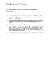
This instructional manual contains information on the MacDon Model M150 and M200 Self-Propelled Windrowers that
are designed to cut and lay in windrows, a wide variety of grain, hay and specialty crops. Windrowing allows starting
the harvest earlier, protects the crop from wind damage, and gives you more flexibility in scheduling combine time.
The power unit (referred to in this manual as the “Windrower”), when coupled with one of the specially designed
auger, rotary, or draper headers, provides a package which incorporates many features and improvements in design.
This manual must be used in conjunction with your Header Operator's Manual.
CAREFULLY READ ALL THE MATERIAL PROVIDED BEFORE ATTEMPTING TO UNLOAD, ASSEMBLE, OR USE
THE MACHINE.
Use this manual as your first source of information about the machine. If you follow the instructions given in this
manual, your M150 and M200 Windrower will work well for many years. If you require more detailed service
information, check with your MacDon Dealer.
Use the Table of Contents and the Index to guide you to specific areas. Study the Table of Contents to familiarize
yourself with how the material is organized.
Keep this manual handy for frequent reference, and to pass on to new operators or owners. Call your MacDon Dealer
if you need assistance, information, or additional copies of this manual. A manual storage case is provided in the cab.
NOTE: The M150 and M200 Windrowers are dual direction, meaning that the Windrower can be driven in the cab-
forward or the engine-forward modes. Right-Hand and Left-Hand designations are therefore determined by the
Operator’s position, facing the direction of travel. This manual uses the terms right cab-forward, left cab-forward, right
engine-forward, and left engine-forward when referencing specific locations on the machine.
RECORD THE SERIAL NUMBERS IN THE SPACES BELOW.
Windrower ___________________________
Serial Number plate is located on the left cab-
forward side of the main frame, near the rear
corner.
Published: September, 2010
M150 Diesel Engine_____________________________
Serial Number plate is located on the top face of the
engine cylinder head cover.
M200 Diesel Engine_____________________________
Serial Number plate is located on the lower right cab-
forward side of the engine block.

TABLE OF CONTENTS
Form 169017 / 169087 / 169095 2 Revision C
Section/Title Page
1
INTRODUCTION ...............................................................................................................................1
2 SAFETY ............................................................................................................................................6
2.1 SAFETY ALERT SYMBOL .......................................................................................................6
2.2 SIGNAL WORDS ......................................................................................................................6
2.3 SAFETY SIGNS ........................................................................................................................6
2.3.1 Safety Sign Installation .................................................................................................................. 6
2.3.2 Safety Sign Locations .................................................................................................................... 6
2.4 GENERAL SAFETY ................................................................................................................11
3 DEFINITIONS ..................................................................................................................................13
4 SPECIFICATIONS ..........................................................................................................................14
4.1 WINDROWER DIMENSIONS .................................................................................................14
4.2 SPECIFICATIONS ..................................................................................................................15
5 OPERATOR’S STATION ................................................................................................................17
5.1 OPERATOR CONSOLE .........................................................................................................17
5.2 OPERATOR PRESENCE .......................................................................................................18
5.2.1 Header Drive ................................................................................................................................ 18
5.2.2 Engine and Transmission ............................................................................................................ 18
5.3 SEAT ADJUSTMENTS ...........................................................................................................18
5.4 TRAINING SEAT ....................................................................................................................19
5.5 SEAT BELTS ..........................................................................................................................19
5.6 STEERING COLUMN ADJUSTMENT ...................................................................................19
5.7 LIGHTS ...................................................................................................................................20
5.7.1 Cab-Forward Lighting - Field ....................................................................................................... 20
5.7.2 Engine-Forward Lighting - Road .................................................................................................. 21
5.7.3 Cab-Forward Lighting - Road (Optional) ...................................................................................... 21
5.7.4 Beacon Lighting - Export (N.A. Optional) ..................................................................................... 22
5.7.5 Slow Moving Vehicle (SMV) Signs ............................................................................................... 22
5.8 WINDSHIELD WIPERS ..........................................................................................................23
5.9 REAR VIEW MIRRORS ..........................................................................................................23
5.10 CAB TEMPERATURE ............................................................................................................23
5.10.1 Heater Shut-Off Valve .................................................................................................................. 23
5.10.2 Air Distribution ............................................................................................................................. 23
5.10.3 Controls ....................................................................................................................................... 24
5.10.4 A/C Compressor Protection ......................................................................................................... 24
5.11 INTERIOR LIGHTS .................................................................................................................24
5.12 OPERATOR AMENITIES .......................................................................................................25
5.13 RADIOS ..................................................................................................................................26
5.13.1 AM/FM Radio ............................................................................................................................... 26
5.13.2 Antenna Mounting ........................................................................................................................ 26
5.14 HORN .....................................................................................................................................26
5.15 ENGINE CONTROLS/GAUGES .............................................................................................27
5.16 WINDROWER CONTROLS ...................................................................................................28
5.17 HEADER CONTROLS ............................................................................................................29
5.17.1 Header Engage Switch ................................................................................................................ 29
5.17.2 Header Drive Reverse Button ...................................................................................................... 29
5.17.3 Ground Speed Lever (GSL) Header Switches ............................................................................. 30
5.17.4 Console Header Switches ............................................................................................................ 32
5.18 CAB DISPLAY MODULE (CDM) ............................................................................................33
5.18.1 Engine and Windrower Functions ................................................................................................ 33
5.18.2 Header Functions ........................................................................................................................ 33
5.18.3 Operating Screens ....................................................................................................................... 34
5.18.4 Cab Display Module (CDM) Warnings/Alarms ............................................................................. 41
5.18.5 Cab Display Module (CDM) Programming ................................................................................... 44
5.18.6 Setting Guidelines ........................................................................................................................ 50
5.18.7 CDM and WCM Fault Codes ....................................................................................................... 50
6 OPERATION ...................................................................................................................................51
6.1 OWNER/OPERATOR RESPONSIBILITIES ...........................................................................51

TABLE OF CONTENTS
Form 169017 / 169087 / 169095 3 Revision C
6.2
SYMBOL DEFINITIONS ......................................................................................................... 51
6.2.1 Engine Functions ......................................................................................................................... 51
6.2.2 Windrower Operating Symbols .................................................................................................... 51
6.2.3 Header Functions ........................................................................................................................ 52
6.3 WINDROWER OPERATION .................................................................................................. 53
6.3.1 Operational Safety ....................................................................................................................... 53
6.3.2 Break-In Period ............................................................................................................................ 53
6.3.3 Pre-Season Check ...................................................................................................................... 54
6.3.4 Daily Check ................................................................................................................................. 54
6.3.5 Engine Operation ......................................................................................................................... 55
6.3.6 Driving The Windrower ................................................................................................................ 59
6.3.7 Adjustable Caster Tread Width .................................................................................................... 65
6.3.8 Transporting ................................................................................................................................ 66
6.3.9 Storage ........................................................................................................................................ 76
6.4 HEADER OPERATION ........................................................................................................... 77
6.4.1 Header Lift Cylinder Stops ........................................................................................................... 77
6.4.2 Header Flotation .......................................................................................................................... 78
6.4.3 Levelling ...................................................................................................................................... 81
6.4.4 Header Drive ............................................................................................................................... 82
6.4.5 Header Angle ............................................................................................................................... 83
6.4.6 Cutting Height .............................................................................................................................. 85
6.4.7 Double Windrowing ..................................................................................................................... 87
6.5 D SERIES HEADER OPERATION ......................................................................................... 88
6.5.1 Header Attachment ...................................................................................................................... 88
6.5.2 Header Detachment .................................................................................................................... 91
6.5.3 Header Position ........................................................................................................................... 94
6.5.4 Reel Fore-Aft Position ................................................................................................................. 94
6.5.5 Reel Height .................................................................................................................................. 94
6.5.6 Reel Speed .................................................................................................................................. 94
6.5.7 Draper Speed .............................................................................................................................. 97
6.5.8 Knife Speed ................................................................................................................................. 99
6.5.9 Deck Shift (Optional) ................................................................................................................. 100
6.6 A SERIES HEADER OPERATION ....................................................................................... 101
6.6.1 Header Attachment .................................................................................................................... 101
6.6.2 Header Detachment .................................................................................................................. 104
6.6.3 Auger Speed.............................................................................................................................. 106
6.6.4 Reel Speed ................................................................................................................................ 107
6.6.5 Knife Speed ............................................................................................................................... 108
6.7 R SERIES HEADER OPERATION ....................................................................................... 109
6.7.1 Header Attachment .................................................................................................................... 109
6.7.2 Header Detachment .................................................................................................................. 112
6.7.3 Disc Speed ................................................................................................................................ 114
6.7.4 Converging Drum Assemblies - Grass Seed Header ................................................................ 115
7 MAINTENANCE AND SERVICING .............................................................................................. 116
7.1 PREPARATION FOR SERVICING ...................................................................................... 116
7.1.1 Welding Precautions .................................................................................................................. 116
7.2 RECOMMENDED SAFETY PROCEDURES ....................................................................... 116
7.3 MAINTENANCE SPECIFICATIONS .................................................................................... 117
7.3.1 Recommended Fuel, Fluids and Lubricants .............................................................................. 117
7.3.2 Recommended Torques ............................................................................................................ 118
7.3.3 Conversion Chart ....................................................................................................................... 120
7.4 ENGINE COMPARTMENT HOOD ....................................................................................... 121
7.5 MAINTENANCE PLATFORMS ............................................................................................. 122
7.5.1 Opening/Closing Platforms ........................................................................................................ 122
7.5.2 Opening/Closing Platform for Major Servicing ........................................................................... 122
7.6 LUBRICATING THE WINDROWER ..................................................................................... 124
7.6.1 Procedure .................................................................................................................................. 124
7.6.2 Lubrication Points ...................................................................................................................... 124
7.7 OPERATOR’S STATION ...................................................................................................... 126
7.7.1 Seat Belts .................................................................................................................................. 126
7.7.2 Safety Systems .......................................................................................................................... 126
7.7.3 GSL Adjustments ....................................................................................................................... 127
7.7.4 Steering Adjustments ................................................................................................................ 128

TABLE OF CONTENTS
Form 169017 / 169087 / 169095 4 Revision C
7.7.5 Park Brake ................................................................................................................................. 130
7.7.6 HVAC System ............................................................................................................................ 132
7.8 CUMMINS ENGINE (M150) ................................................................................................ 135
7.8.1 General Engine Inspection ......................................................................................................... 135
7.8.2 Manually Turning Engine ........................................................................................................... 135
7.8.3 Oil Level ..................................................................................................................................... 136
7.8.4 Changing Oil and Oil Filter ......................................................................................................... 137
7.8.5 Air Intake System ....................................................................................................................... 139
7.8.6 Fuel System ............................................................................................................................... 142
7.8.7 Engine Cooling System .............................................................................................................. 147
7.8.8 Gearbox ..................................................................................................................................... 150
7.8.9 Exhaust System ......................................................................................................................... 152
7.8.10 Belts ........................................................................................................................................... 153
7.8.11 Engine Speed ............................................................................................................................ 154
7.9 CAT ENGINE (M200) .......................................................................................................... 155
7.9.1 General Engine Inspection ......................................................................................................... 155
7.9.2 Oil Level ..................................................................................................................................... 155
7.9.3 Changing Oil and Oil Filter ......................................................................................................... 156
7.9.4 Air Intake System ....................................................................................................................... 157
7.9.5 Aspirator Hose and Check Valve Replacement ......................................................................... 159
7.9.6 Fuel System ............................................................................................................................... 161
7.9.7 Engine Cooling System .............................................................................................................. 166
7.9.8 Gearbox ..................................................................................................................................... 170
7.9.9 Exhaust System ......................................................................................................................... 172
7.9.10 Belts ........................................................................................................................................... 173
7.10 COOLING BOX .................................................................................................................... 175
7.10.1 Cooling Box Screen ................................................................................................................... 175
7.10.2 Cooling Box Maintenance .......................................................................................................... 177
7.11 ELECTRICAL SYSTEM ....................................................................................................... 179
7.11.1 Battery ....................................................................................................................................... 179
7.11.2 Headlights - Engine-Forward ..................................................................................................... 184
7.11.3 Field lights - Cab-Forward .......................................................................................................... 186
7.11.4 Flood Lights - Forward ............................................................................................................... 186
7.11.5 Flood Lights - Rear .................................................................................................................... 187
7.11.6 Red and Amber Lights ............................................................................................................... 188
7.11.7 Red Tail Lights (If Installed) ....................................................................................................... 189
7.11.8 Beacons (If Installed) ................................................................................................................. 189
7.11.9 Gauge Light ............................................................................................................................... 191
7.11.10 Dome Light ................................................................................................................................ 191
7.11.11 Ambient Light ............................................................................................................................. 191
7.11.12 Turn Signal Indicators ................................................................................................................ 191
7.11.13 Circuit Breakers and Fuses ........................................................................................................ 192
7.12 HYDRAULIC SYSTEM ........................................................................................................ 195
7.12.1 Oil Level ..................................................................................................................................... 195
7.12.2 Changing Hydraulic Oil .............................................................................................................. 196
7.12.3 Hydraulic Oil Cooler ................................................................................................................... 196
7.12.4 Hydraulic Oil Filters .................................................................................................................... 196
7.12.5 Header and Reel Hydraulics ...................................................................................................... 197
7.12.6 Traction Drive Hydraulics ........................................................................................................... 199
7.12.7 Hoses and Lines ........................................................................................................................ 200
7.13 WHEELS AND TIRES ......................................................................................................... 201
7.13.1 Drive Wheels ............................................................................................................................. 201
7.13.2 Caster Wheels ........................................................................................................................... 204
7.14 MAINTENANCE SCHEDULE .............................................................................................. 208
7.14.1 Break-In Inspections .................................................................................................................. 208
7.14.2 Interval Maintenance ................................................................................................................. 209
8 TROUBLESHOOTING ................................................................................................................. 212
8.1 ENGINE ............................................................................................................................... 212
8.2 ELECTRICAL ....................................................................................................................... 215
8.3 HYDRAULICS ...................................................................................................................... 215
8.4 HEADER DRIVE .................................................................................................................. 216
8.5 TRACTION DRIVE .............................................................................................................. 216
8.6 STEERING AND GROUND SPEED CONTROL ................................................................. 217

TABLE OF CONTENTS
Form 169017 / 169087 / 169095 5 Revision C
8.7
CAB AIR ................................................................................................................................ 218
8.8 OPERATOR’S STATION ...................................................................................................... 220
9 OPTIONS / ATTACHMENTS ........................................................................................................ 221
9.1 REEL DRIVE AND LIFT PLUMBING ................................................................................... 221
9.2 WINDROWER HYDRAULIC COMPLETION FOR DRAPER HEADER REEL FORE-AFT . 221
9.3 DOUBLE WINDROW ATTACHMENT .................................................................................. 221
9.4 REVERSER VALVE AND PLUMBING ................................................................................. 221
9.5 BOOSTER SPRING KIT ....................................................................................................... 221
9.6 INTERNAL BOOSTER SPRING KIT .................................................................................... 221
9.7 LIGHT HEADER FLOTATION KIT ....................................................................................... 221
9.8 WINDSHIELD SHADES ....................................................................................................... 221
9.9 DISC HEADER VALVE ......................................................................................................... 221
9.10 AM/FM RADIO ...................................................................................................................... 221
9.11 CENTER-LINK SELF-ALIGNMENT KIT ............................................................................... 221
9.12 PRESSURE SENSOR KIT ................................................................................................... 221
9.13 HYDRAULIC CENTER-LINK ................................................................................................ 221
9.14 WEIGHT BOX ....................................................................................................................... 221
9.15 TOWING HARNESS ............................................................................................................. 221
9.16 SWATH ROLLER ................................................................................................................. 221
9.17 WARNING BEACONS .......................................................................................................... 222
9.18 AUTO-STEER ....................................................................................................................... 222
9.19 LIGHTING AND MARKING KIT FOR CAB-FORWARD ROAD TRAVEL ............................ 222
9.20 FAN AIR BAFFLE KIT .......................................................................................................... 222
INDEX ......................................................................................................................................................... 223
CDM / WCM FAULT CODES ..................................................................................................................... 226
M150 AND M200 ENGINE ERROR CODES .............................................................................................. 227

SAFETY
Form 169017 / 169087 / 169095 6 Revision C
2 SAFETY
2.1 SAFETY ALERT SYMBOL
This safety alert symbol indicates important safety
messages in this manual and on safety signs on
the machine.
This symbol means:
ATTENTION!
BECOME ALERT!
YOUR SAFETY IS INVOLVED!
Carefully read and follow the safety message
accompanying this symbol.
WHY IS SAFETY IMPORTANT TO YOU?
ACCIDENTS DISABLE AND KILL.
ACCIDENTS COST.
ACCIDENTS CAN BE AVOIDED.
2.2 SIGNAL WORDS
Note the use of the signal words DANGER,
WARNING, and CAUTION with safety messages.
The appropriate signal word for each message
has been selected using the following guidelines:
DANGER
Indicates an imminently hazardous situation
that, if not avoided, will result in death or
serious injury.
WARNING
Indicates a potentially hazardous situation
that, if not avoided, could result in death or
serious injury. It is also used to alert against
unsafe practices.
CAUTION
Indicates a potentially hazardous situation
that, if not avoided, may result in minor or
moderate injury. It is also used as a reminder
of good safety practices.
2.3 SAFETY SIGNS
2.3.1 SAFETY SIGN INSTALLATION
Refer to the illustration on this and following
pages, and proceed as follows:
a. Be sure the installation area is clean and dry.
b. Decide on the exact location before you remove
the decal backing paper.
c. Remove the smaller portion of the split backing
paper.
d. Place the sign in position and slowly peel back the
remaining paper, smoothing the sign as it is
applied.
e. Small air pockets can be smoothed out or pricked
with a pin.
2.3.2 SAFETY SIGN LOCATIONS
The safety signs (decals) appear on the windrower
at the locations approximately as shown.
• Keep safety signs clean and legible at all
times.
• Replace safety signs that are missing or
become illegible.
• If original parts on which a safety sign was
installed are replaced, be sure the repair part
also bears the current safety sign.
• Safety signs are available from your MacDon
Dealer Parts Department.

SAFETY
Form 169017 / 169087 / 169095 7 Revision C
Safety Sign Locations (continued)
LIFT LINKAGES #163561
FRONT OF PLATFORM #134070
(HORIZONTAL FORMAT), AND
ON OIL RESERVOIR UNDER HOOD
(BOTH SIDES) #44944 (VERTICAL FORMAT)
BELOW DOOR HANDLE #32744
IN CAB #32744
BEHIND DOOR ON SILL - LH SIDE ONLY
#160396
BEHIND DOOR ON SILL #109843

SAFETY
Form 169017 / 169087 / 169095 8 Revision C
Safety Sign Locations
(continued)
IN CAB #109868
IN CAB #109844
BEHIND DOOR ON SILL #109843
FRONT OF PLATFORM #110989
IN CAB #160422
BEL0W DOOR HANDLE #32744

SAFETY
Form 169017 / 169087 / 169095 9 Revision C
Safety Sign Locations (continued)
ON FRAME #42130
ON FAN SHROUD #134068
ON FRAME #110986

SAFETY
Form 169017 / 169087 / 169095 10 Revision C
Safety Sign Locations
(continued)
ON DRINK COOLER #160429
INSIDE FRAME #32743
ON FRAME #110986
ON LIFT LINKAGE #163562

SAFETY
Form 169017 / 169087 / 169095 11 Revision C
2.4 GENERAL SAFETY
CAUTION
The following are general farm safety
precautions that should be part of your
operating procedure for all types of
machinery.
Protect yourself.
• When assembling, operating and servicing
machinery, wear all the protective clothing
and personal safety devices that COULD
be necessary for the job at hand. Don't
take chances.
• You may need:
• a hard hat.
• protective shoes with slip resistant
soles.
• protective glasses or goggles.
• heavy gloves.
• wet weather gear.
• respirator or filter mask.
• hearing protection. Be aware that
prolonged exposure to loud noise
can cause impairment or loss of
hearing. Wearing a suitable hearing
protective device such as ear muffs
(A) or ear plugs (B) protects against
objectionable or loud noises.
• Provide a first-aid kit for use in case of
emergencies.
• Keep a fire extinguisher on the machine.
Be sure the extinguisher is properly
maintained and be familiar with its proper
use.
• Keep young children away from machinery
at all times.
• Be aware that accidents often happen
when the operator is tired or in a hurry to
get finished. Take the time to consider the
safest way. Never ignore warning signs of
fatigue.
• Wear close-fitting
clothing and cover
long hair. Never wear
dangling items such
as scarves or
bracelets.
• Keep hands, feet, clothing and hair away
from moving parts. Never attempt to clear
obstructions or objects from a machine
while the engine is running.
• Keep all shields in place. Never alter or
remove safety equipment. Make sure
driveline guards can rotate independently
of the shaft and can telescope freely.
• Use only service and repair parts made or
approved by the equipment manufacturer.
Substituted parts may not meet strength,
design, or safety requirements.
(continued next page)
A
B

SAFETY
Form 169017 / 169087 / 169095 12 Revision C
• Do not modify the machine. Unauthorized
modifications may impair the function
and/or safety and affect machine life.
• Stop engine and remove key from ignition
before leaving Operator’s seat for any
reason. A child or even a pet could engage
an idling machine.
• Keep the area used for servicing
machinery clean and dry. Wet or oily floors
are slippery. Wet spots can be dangerous
when working with electrical equipment.
Be sure all electrical outlets and tools are
properly grounded.
• Use adequate light for the job at hand.
• Keep machinery clean. Straw and chaff on
a hot engine are a fire hazard. Do not allow
oil or grease to accumulate on service
platforms, ladders or controls. Clean
machines before storage.
• Never use gasoline, naphtha or any volatile
material for cleaning purposes. These
materials may be toxic and/or flammable.
• When storing machinery, cover sharp or
extending components to prevent injury
from accidental contact.

SPECIFICATIONS
Form 169017 / 169087 / 169095 13 Revision C
3 DEFINITIONS
TERM DEFINITION
API American Petroleum Institute
ASTM American Society of Testing And Materials
Cab-Forward Windrower operation with the operator and cab facing in the direction of travel
CDM Cab Display Module
DWA Double Windrow Attachment
Engine-Forward Windrower operation with the operator and engine facing in the direction of travel
ISC Integrated Speed Control
N-DETENT The slot opposite the neutral position on operator’s console
rpm Revolutions per minute
SAE Society Of Automotive Engineers
WCM Windrower Control Module
Windrower Windrower with header attached
Windrower Tractor Power unit only. (Windrower without the header attached)

SPECIFICATIONS
Form 169017 / 169087 / 169095 14 Revision C
4 SPECIFICATIONS
4.1 WINDROWER DIMENSIONS
Dimensions are with 18.4 - 26 drive tires and forked casters.
WHEEL
POSITION
TREAD
Inch (mm)
HUBS
Inch (mm)
CASTERS
Inch (mm)
TIRES
Inch (mm)
SHIPPING
Inch (mm)
WHEEL BASE
Inch (mm)
CAB
FWD
ENG
FWD
DRIVE
TIRE
Inner / Outer - 138.7 (3522) - -
142.9
(3630)
158.3
(4021)
120.7
(3066)
Outer / Outer 134.2 (3410) 146.1 (3712) - 157.1 (3990)
Inner / Inner 120.1 (3050) 131.6 (3342) - 150.0 (3810)
CASTER
TIRE
Minimum 93.2 (2367) - 115.4 (2932) - -
Maximum 135.8 (3448) - 158.0 (4013) - -
ENGINE - FORWARD
TREAD
CASTERS
CAB - FORWARD
45.7 in. (1160
TREAD
HUBS
TIRES
WHEEL BASE
WHEEL BASE
133 in. (3378 mm)

SPECIFICATIONS
Form 169017 / 169087 / 169095 15 Revision C
4.2 SPECIFICATIONS
M150 M200
ENGINE
Type Cummins QSB -130 4 Cyl. Turbo Cat C6.6 6 Cyl. Turbo
Displacement 275 cu.in. (4.5 L) 403 cu.in. (6.6 L)
Power
Rated
130 hp (97 kW) @ 2200 rpm 213 hp (159 kW) @ 2200 rpm
Peak
140 hp (104 kW) @ 2000 rpm 220 hp (164 kW) @ 2000 rpm
Bore 4.04 in. (102 mm) 4.13 in. (105 mm)
Stroke 5.39 in. (137 mm) 5.00 in. (127 mm)
Maximum RPM (no load) 2270 - 2330 2250 - 2300
Idle RPM 1100 1100
ELECTRICAL SYSTEM
Recommended Battery (2)
12 Volt, Min. 750CCA, Max Dim - 13 x 6.81 x 9.43 in. (330 x 173 x 240 mm).
Group Rating 31A. Heavy Duty / Off Road / Vibration Resistant.
Alternator 130 amp 120 amp
Starter
Wet Type
Working Lights
11
TRACTION DRIVE
Type Hydrostatic, 3 Speed Electric Shift
Speed
Field (Cab-Forward)
Low Range 0 - 11 mph (17.7 km/h)
Mid Range 0 - 16 mph (25.7 km/h)
Reverse (Cab-Forward)
6 mph (9.6 km/h)
Transport (Engine-Forward)
High Range 0 - 23 mph (37 km/h)
Transmission
Type
2 Piston Pumps - 1 per Drive Wheel.
Displacement
2.65 cu.in. (44 cc)
Flow
40 U.S. gpm (151 L/min)
Final Drive
Type
Planetary Gearbox
Ratio
30.06 : 1
Wheel Motor Displ.
Low Range
4.15 cu.in. (68 cc)
Mid Range
2.93 cu.in. (48 cc)
High Range
2.0 cu.in. (33 cc)
SYSTEM CAPACITIES
Fuel Tank
97 U.S. Gallons (378 L)
Cooling
5.1 U.S. Gallons (20 L)
Hydraulic Reservoir
17.2 U.S. Gallons (66 L)
HEADER DRIVE
Type Hydraulic, Load Sensing Variable Displacement
Piston Pumps
Displacement
Pump A - 0 - 2.75 cu.in. (0 - 45 cc)
Pump B - 0 - 2.32 cu.in. (0 - 38 cc)
Pumps A & B - 0 - 3.11 cu.in. (0 - 51 cc)
Flow
Pump A
0 - 27 U.S. gpm (102 L/min) 0 - 39 U.S. gpm (148 L/min)
Pump B
0 - 24 U.S. gpm (91 L/min) 0 - 34 U.S. gpm (128 L/min)
Max
Pressure
Pump A
4000 psi (27.58 MPa) 4800 psi (33.10 MPa)
Pump B
3200 psi (22.06 MPa) 4800 psi (33.10 MPa)
(continued next page)

SPECIFICATIONS
Form 169017 / 169087 / 169095 16 Revision C
M150 M200
HEADER LIFT/TILT
Type
Hydraulic
Gear Pumps (2)
Displacement 0.84 cu.in. (13.8 cc)
Flow 11.5 U.S. gpm (46.5 L/min)
System Pressure (Relief / Max)
2500 psi (17.24 MPa)
HEADER FLOTATION
Primary Adjustment
Manual, External, Draw-Bolt With Springs (1 per side)
Fine Adjustment
Hydraulic, In-Cab Switch
Automatic
Hydraulic, 3 Programmable Settings For All Headers
(Deck Shift Compensation On Draper Headers)
CAB
Dimensions
Width
63 in. (1600 mm)
Depth
68.3 in. (1735 mm) (at top of window)
Height
64.6 in. (1640 mm)
Volume
125 cu.ft. (3540 L)
Seat
Driver
Adjustable Air-Ride Suspension, Seat Belt
Training
Folding, Cab Mounted, Seat Belt
Windshield Wiper
Front
31.5 in. (800 mm) Blade
Rear
22 in. (560 mm) Blade
Heater
24,000 Btu/h (7038 W)
Air Conditioning
28,280 Btu/h (8288 W)
Electrical Outlets
Two Live, Three On Ignition
Mirrors
One Inside (Transport), Two Outside (Field)
Radio
Two Speakers and Antenna Factory Installed. Radio Dealer Installed
SYSTEM MONITORING
Speeds
Ground (mph or km/h), Engine (rpm), Knife (spm), Disc (rpm),
Reel (rpm or mph/km/h), Conveyor (Ref. No.)
Header
Height, Angle, Float, Optional Knife or
Reel Drive Pressure
Height, Angle, Float, Knife Drive and
Reel Drive Pressures
TIRE OPTIONS
Size
Drive
18.4 - 26 Bar, 18.4 - 26 Turf, 600-65 R28 Bar, 23.1 - 26 Turf, 580-70 R26 Turf
Rear
7.5 - 16SL Single Rib, 10 x 16 Front Steer Tire
16.5L - 16.1 Rib Implement Flotation, Forked Caster
Pressure
Drive
Bar - 32 psi (221 kPa), Turf - 20 psi (138 kPa)
Rear
10 psi (69 kPa)
FRAME AND STRUCTURE
Dimensions
Refer to Section 4.1 WINDROWER DIMENSIONS
Frame to Ground (Crop Clearance)
45.7 in. (1160 mm)
Weight
Base
10,700 lb (4858 kg) 11,400 lb (5176 kg)
Max GVW
21,500 (9750 kg)
Max CGVW
23,100 lb (10,480 kg)
NG Header Compatibility
SK
A30S Auger, D50, D60S Harvest Header
DK
A30D, A40D Auger, D60D Harvest Header
R80 Disc Rotary Header
NOTES: 1. Specifications and design are subject to change without notice, or obligation to revise previously sold units.
2. Weights do not include options
.

OPERATOR’S STATION
Form 169017 / 169087 / 169095 17 Revision C
5 OPERATOR’S STATION
The Operator’s station is designed for operating
the windrower in a cab-forward mode (working
mode), or in an engine-forward mode (transport
mode).
The operator station, which includes the seat,
console, and steering column, pivots 180° so that
the operator maintains access to the windrower
controls and gauges regardless of the direction of
travel.
5.1 OPERATOR CONSOLE
The console contains controls to operate the
windrower, as well as amenities for the operator.
The console position is adjustable to suit each
particular operator. The console is attached to the
seat, and does not require adjustment when
repositioning the Operator’s seat.
a. Pull lever (A), and slide console fore or aft to
desired position. The height also increases
slightly as the console is moved aft. Release lever
to lock console.
b. To adjust only fore-aft, loosen nuts (B) under
console and move as required.
c. Tighten nuts.
A
HEADER
CONTROLS
SECTION 5.17
WINDROWER CONTROLS
SECTION 5.16
THROTTLE
ENGINE / WINDROWER
CAB DISPLAY MODULE
(
CDM
)
B

OPERATOR’S STATION
Form 169017 / 169087 / 169095 18 Revision C
5.2 OPERATOR PRESENCE
The Operator Presence System is a safety feature
that is designed to deactivate or alarm selected
systems when the operator is not seated at the
Operator’s station.
These systems include:
• Header Drive
• Engine and Transmission
5.2.1 HEADER DRIVE
• Requires the operator to be seated in the seat
in order to engage the header drive.
• Power is maintained to the header drive for 5
seconds after the operator leaves the seat,
and then the header shuts down.
• After the header has shutdown automatically,
the header engage switch must be moved to
“OFF” position, and back to the “ON” position
again to restart the header.
5.2.2 ENGINE AND TRANSMISSION
• The engine will not be allowed to start when
the header drive switch is engaged.
• The engine will not be allowed to start when
the transmission is not locked in neutral.
• The engine will shutdown when the windrower
is moving at 5 mph (8 km/h) or less, and the
operator leaves the seat.
• If the operator leaves the seat and the
transmission is not locked in neutral, after 5
seconds the lower display will flash “NOT IN
NEUTRAL” accompanied by an alarm.
• When the seat is in between cab-forward and
engine-forward positions, the engine will shut
off if the transmission is not locked in the
neutral position. The lower display will flash
“LOCK SEAT BASE” until the seat base is
locked into position.
5.3 SEAT ADJUSTMENTS
The Operator’s seat has several adjustments.
Refer to the following illustration for the location
and description of each adjustment.
SEAT FORE-AFT POSITION
Adjusts Fore-Aft Position
Pull Lever Up To Release.
Move Seat Forward or Rearward.
Release Lever.
LUMBAR SUPPORT
Adjusts Stiffness of Seat Back
INCREASE - Rotate Knob Upward.
DECREASE - Rotate Knob Downward.
OPERATOR WEIGHT AND SEAT HEIGHT
Controls Suspension Stiffness and Seat Height
INCREASE - Press Upper Switch.
DECREASE - Press Lower Switch.
ARM REST ANGLE
Adjusts Angle of Arm Rest
INCREASE - Rotate Knob Clockwise.
DECREASE - Rotate Knob Counter
Clockwise.
ARM REST
Raise Arm Rest For Easier
Access To Seat.
Lower Arm Rest After Seat
Belt Is Buckled.
SEAT BACK ANGLE
Pull Lever Up To Release.
Position Seat Back As Desired.
Release Lever.
VERTICAL DAMPENER
Adjusts Suspension Dampening
INCREASE - Turn Knob Counter Clockwise
DECREASE - Turn Knob Clockwise
SEAT FORE-AFT ISOLATOR LOCK
Locks Seat Fore-Aft Isolator
LOCK - Push Lever Down.
UNLOCK - Pull Lever Up.
/