Fujitsu MAT3073NP User manual
- Category
- Internal hard drives
- Type
- User manual

MAW3300NC/NP, MAW3147NC/NP,
MAW3073NC/NP
DISK DRIVES INSTALLATION GUIDE
CARE OF YOUR FUJITSU DRIVE
Careful handling and installation of your disk drive is paramount to the longevity of the unit. Serious damage can occur to the internal
mechanisms if forces outside the environmental specifications are exerted to the casing. In transportation, always use the original packing
in which the drive was supplied and avoid sharp changes in temperature to minimise the risk of condensation.
Handling
1. Never drop. Handle with care.
2. Never move the disk drive while the disks are spinning. This is when the drive is powered on and also immediately after power off.
Refer to the Start/Stop specification for your drive.
3. Always turn off the power before connecting or disconnecting the interface cable. The same applies to changing any of the switches or
terminal settings except Write protect switch on NP model drives.
4. Never place the drive in the vicinity of strong magnetic fields such as monitors, televisions, or loudspeakers.
5. Never use any cleaning agents or liquids on the drive.
6. Always use an antistatic mat and wrist strap when handling the drive. Hold the drive by the Base casting and never touch the components
on printed circuit board.
7. Never remove any labels from the drive and do not deface them in any way; these labels are part of the disk drive design.
8. Never open the disk enclosure for any reason. Doing so voids any warranty.
9. Always pay close attention to the mounting specifications such as sway space and cooling. If the temperature difference between storage
location and installation locations is more than 10°C, leave the drive in the new location for at least two hours for Temperature acclimation.
This minimises any risk of condensation forming on the drive.
The Drive needs NO preventative or periodic maintenance during its life time if properly used in the correct environment.
INSTALLATION
1. ORIENTATION–The drive can be installed in each six surface down orientations. Inclination from vertical or horizontal should not
exceed 5
°.
2. MOUNTING SCREW INSTALLATION–When the mounting screw holes on the side of the drive are used, be sure to use the two pairs
of outer holes. Do not use the center hole in conjunction with only one of the outer holes. The screws must not penetrate the drive by more
than 5.0 millimeters. Impact caused by the electric driver must be within the device specifications.
3. COOLING–Allow space above and below the drive to provide an adequate air flow. Fan cooling is recommended. The disk enclosure
temperature measured at center of base cover (label side) should never exceed 60°C. See Table 1.
Table 1. Reference value of airflow
Environmental temperature Required velocity of airflow
35
°C > 0.2m/s
40
°C > 0.5 m/s
45°C > 0.9 m/s
50°C > 1.5 m/s
4. TERMINATION–A terminator should be installed externally at both ends of the SCSI bus.
5. TERMINATOR POWER–Terminator power must be supplied to terminator for correct operation. This can be supplied from either the
drive, except for NC model or the SCSI bus. If only NC model drives are connected to the SCCI bus, terminator power should be supplied
externally.
6. ATTACHING THE CABLES–To avoid possible damage to the drive, make sure the direction of the connector matches.
CAUTION: Warranty may be avoided if damage to the connector is caused by wrong insertion.
FUJITSU LIMITED
Storage Products Group
4-1-1 Kamikodanaka, Nakahara-ku, Kawasaki 211-8588, Kanagawa-ken, Japan
Copyright © 2005 FUJITSU LIMITED
Corporate http://www.jp.fujitsu.com/
USA http://www.fcpa.com/
EUROPE http://www.fujitsu-europe.com/
C141-E227-01EN

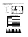
Diagram and user-selectable options (on NP models only)
Below is a diagram of the main board of SCSI disk drives and also a summary of the user-selectable options including guidelines for
installation of the drives.
This setting applies only for NP model drives.
Pin 24
Pin 23
Pin 2
CN2
Pin 1
Figure 1. Option select terminal
Table 2. CN2 Terminal Setting (on NP models only)
Pin #
Setting Item
Function
1-2 SCSI ID 0 See Table 3.
3-4 SCSI ID 1
5-6 SCSI ID 2
7-8 SCSI ID 3
9-10 Write protect Open ……Write operation is enabled. (default)
Short
……Write operation is disabled.
11-12 Motor start mode Open ……Starting of motor is controlled with START/STOP
UNIT command.
Short
……Motor is started immediately after power supply is
turned on or microcode is downloaded.
(default)
13-14 Force Narrow Open ……16-bit bus mode (default)
Short
……Pull upper 8bits and parity internally when drive is
connected to Narrow SCSI bus.
15-16 Force Single Ended Open ……Follows DIFFSNS signal level on SCSI bus. (default)
Short ……Single-Ended mode
17 GND
18, 19 N.C
20 IDD Reset Input signal
21-22 Remote LED Output signal
23-24 Terminal power supply Open ……Drive does not supply terminator power to SCSI bus.
Short ……Drive supplies terminator power to SCSI bus. (default)
Table 3. SCSI ID Setting on CN2 (on NP models only)
Pin 1-2 Pin 3-4 Pin 5-6 Pin 7-8 ID Pin 1-2 Pin 3-4 Pin 5-6 Pin 7-8 ID
Open Open Open Open 0 Open Open Open Short 8
Short Open Open Open 1 Short Open Open Short 9
Open Short Open Open 2 Open Short Open Short 10
Short Short Open Open 3 Short Short Open Short 11
Open Open Short Open 4 Open Open Short Short 12
Short Open Short Open 5 Short Open Short Short 13
Open Short Short Open 6 Open Short Short Short 14
Short Short Short Open 7 Short Short Short Short 15 (default)
-
 1
1
-
 2
2


Fujitsu MAT3073NP User manual
- Category
- Internal hard drives
- Type
- User manual
Ask a question and I''ll find the answer in the document
Finding information in a document is now easier with AI
Related papers
-
Fujitsu C141-E238-01EN User manual
-
-
-
Fujitsu MBA3147NC User manual
-
-
-
Fujitsu MBA3300NP Installation guide
-
-
-
Other documents
-
American Megatrends MegaRUM User manual
-
 Tekram Technology DC-820B User manual
-
Hitachi HUS157373EL3800 User manual
-
-
Dell PowerVault 110T LTO2 (Tape Drive) User guide
-
Tandberg Data LTO-2 HH User guide
-
Bosch Computer Hardware DVA-08K User manual
-
 Ratoc PCIFS3P Rev.1.0 User manual
-
 PCAvionics Computer Hardware pea-6005 User manual
-
Seagate ST34520LW Datasheet


